Example for Configuring Static BFD for TE
After static BFD for TE is configured, the VPN is enabled to rapidly detect tunnel faults and perform traffic switchover.
Networking Requirements
Figure 1 illustrates an MPLS network. Layer 2 devices (switches) are deployed between PE1 and PE2. PE1 is configured with VPN FRR and the MPLS TE tunnel. The primary path of VPN FRR is PE1 → Switch → PE2; the backup path of VPN FRR is PE1 → PE3. In a normal situation, VPN traffic is transmitted over the primary path. If the primary path fails, VPN traffic is switched to the backup path. BFD for TE is required to monitor the TE tunnel over the primary path and enable VPN to rapidly detect tunnel faults. Traffic rapidly switches between the primary and backup paths, and fault recovery is sped up.

Interfaces 1 and 2 in this example represent GE 0/1/0 and GE 0/1/8, respectively.
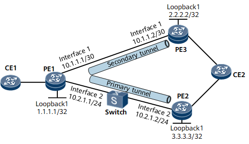
For simplicity, the IP addresses of the interfaces connected the PEs and the CEs are not shown in the diagram.
Configuration Roadmap
The configuration roadmap is as follows:
Configure an MPLS network and establish bidirectional TE tunnels between PE1 and PE2, and between PE1 and PE3.
Configure VPN FRR on PE1.
Enable global BFD on PE1, PE2, and PE3.
Establish a BFD session on PE1 to monitor the TE tunnel over the primary path.
Establish a BFD session on PE2 and PE3, and specify the TE tunnel as the BFD reverse tunnel.
Data Preparation
To complete the configuration, you need the following data:
An IGP and its parameters
BGP AS number and interface names used by BGP sessions
MPLS LSR ID
Tunnel interface number and explicit paths
VPN instance name, RD, and route target (RT)
Name of the tunnel policy
Name of a BFD session
Local and remote discriminators of BFD sessions
Procedure
- Assign an IP address and a mask to each interface.
Assign an IP address to each interface according to Figure 1, create loopback interfaces on routers, and configure the IP addresses of the loopback interfaces as MPLS LSR IDs. For configuration details, see Configuration Files in this section.
- Configure an IGP.
Configure OSPF or IS-IS on each router to ensure interworking between PE1 and PE2, and between PE1 and PE3. OSPF is used in the example. For configuration details, see Configuration Files in this section.
- Configure basic MPLS functions.
On each router, configure an LSR ID and enable MPLS in the system and interface views. For configuration details, see Configuration Files in this section.
- Configure basic MPLS TE functions.
Enable MPLS TE and MPLS RSVP-TE in the MPLS and interface views on each LSR. For configuration details, see Configuration Files in this section.
- Enable OSPF TE and configure the CSPF.
Enable OSPF TE on each router and configure CSPF on PE1. For configuration details, see Configuration Files in this section.
- Configure tunnel interfaces.
Specify explicit paths between PE1 and PE2 and between PE1 and PE3. For PE1, two explicit paths must be specified.
# Configure the explicit paths between PE1 and PE2 and between PE2 and PE3.
[~PE1] explicit-path tope2
[*PE1-explicit-path-tope2] next hop 10.2.1.2
[*PE1-explicit-path-tope2] next hop 3.3.3.3
[*PE1-explicit-path-tope2] quit
[*PE1] explicit-path tope3
[*PE1-explicit-path-tope3] next hop 10.1.1.2
[*PE1-explicit-path-tope3] next hop 2.2.2.2
[*PE1-explicit-path-tope3] commit
[*PE1-explicit-path-tope3] quit
# Configure an explicit path between PE2 and PE1.
[~PE2] explicit-path tope1
[*PE2-explicit-path-tope1] next hop 10.2.1.1
[*PE2-explicit-path-tope1] next hop 1.1.1.1
[*PE2-explicit-path-tope1] commit
[*PE2-explicit-path-tope1] quit
# Configure an explicit path between PE3 and PE1.
[~PE3] explicit-path tope1
[*PE3-explicit-path-tope1] next hop 10.1.1.1
[*PE3-explicit-path-tope1] next hop 1.1.1.1
[*PE3-explicit-path-tope1] commit
[*PE3-explicit-path-tope1] quit
Create tunnel interfaces and specify explicit paths on PE1, PE2, and PE3. Bind the tunnel to the specified VPN. For PE1, two tunnel interfaces must be created. For PE1, two tunnel interfaces must be created.
# Configure PE1.
[~PE1] interface tunnel 2
[*PE1-Tunnel2] ip address unnumbered interface loopback 1
[*PE1-Tunnel2] tunnel-protocol mpls te
[*PE1-Tunnel2] destination 3.3.3.3
[*PE1-Tunnel2] mpls te tunnel-id 2
[*PE1-Tunnel2] mpls te path explicit-path tope2
[*PE1-Tunnel2] mpls te reserved-for-binding
[*PE1-Tunnel2] quit
[*PE1] interface tunnel 1
[*PE1-Tunnel1] ip address unnumbered interface loopback 1
[*PE1-Tunnel1] tunnel-protocol mpls te
[*PE1-Tunnel1] destination 2.2.2.2
[*PE1-Tunnel1] mpls te tunnel-id 1
[*PE1-Tunnel1] mpls te path explicit-path tope3
[*PE1-Tunnel1] mpls te reserved-for-binding
[*PE1-Tunnel1] commit
[~PE1-Tunnel1] quit
# Configure PE2.
[~PE2] interface tunnel 2
[*PE2-Tunnel2] ip address unnumbered interface loopback 1
[*PE2-Tunnel2] tunnel-protocol mpls te
[*PE2-Tunnel2] destination 1.1.1.1
[*PE2-Tunnel2] mpls te tunnel-id 3
[*PE2-Tunnel2] mpls te path explicit-path tope1
[*PE2-Tunnel2] mpls te reserved-for-binding
[*PE2-Tunnel2] commit
[~PE2-Tunnel2] quit
# Configure PE3.
[~PE3] interface tunnel 1
[*PE3-Tunnel1] ip address unnumbered interface loopback 1
[*PE3-Tunnel1] tunnel-protocol mpls te
[*PE3-Tunnel1] destination 1.1.1.1
[*PE3-Tunnel1] mpls te tunnel-id 4
[*PE3-Tunnel1] mpls te path explicit-path tope1
[*PE3-Tunnel1] mpls te reserved-for-binding
[*PE3-Tunnel1] commit
[~PE3-Tunnel1] quit
After completing the preceding configuration, run the display mpls te tunnel-interface tunnel interface-number command on the PEs. The command output shows that the status of tunnel 1 and tunnel 2 on PE1, tunnel 2 on PE2, and tunnel 1 on PE3 is Up.
- Configure VPN FRR.
# Configure a VPN instance on PE1, PE2, and PE3. Set the VPN instance name to vpn1, RDs to 100:1, 100:2, and 100:3 respectively, and all RTs to 100:1. Configure the CEs to access the PEs. For configuration details, see Configuration Files in this section.
# Establish MP IBGP peer relationship between PE1 and PE2, and between PE1 and PE3. The BGP AS number of PE1, PE2, and PE3 are 100. The loopback interface Loopback1 on PE1, PE2, and PE3 is used as the interface to establish BGP sessions. For configuration details, see Configuration Files in this section.
# Configure tunnel policies for PE1, PE2, and PE3 and apply the policies to the VPN instances.
# Configure PE1.
[~PE1] tunnel-policy policy1
[*PE1-tunnel-policy-policy1] tunnel binding destination 3.3.3.3 te tunnel 2
[*PE1-tunnel-policy-policy1] tunnel binding destination 2.2.2.2 te tunnel 1
[*PE1-tunnel-policy-policy1] quit
[*PE1] ip vpn-instance vpn1
[*PE1-vpn-instance-vpn1] tnl-policy policy1
[*PE1-vpn-instance-vpn1] quit
# Configure PE2.
[~PE2] tunnel-policy policy1
[*PE2-tunnel-policy-policy1] tunnel binding destination 1.1.1.1 te tunnel 2
[*PE2-tunnel-policy-policy1] quit
[*PE2] ip vpn-instance vpn1
[*PE2-vpn-instance-vpn1] tnl-policy policy1
[*PE2-vpn-instance-vpn1] commit
[~PE2-vpn-instance-vpn1] quit
# Configure PE3.
[~PE3] tunnel-policy policy1
[*PE3-tunnel-policy-policy1] tunnel binding destination 1.1.1.1 te tunnel 1
[*PE3-tunnel-policy-policy1] quit
[*PE3] ip vpn-instance vpn1
[*PE3-vpn-instance-vpn1] tnl-policy policy1
[*PE3-vpn-instance-vpn1] commit
[~PE3-vpn-instance-vpn1] quit
# Configure VPN FRR on PE1.
[~PE1] bgp 100
[*PE1-bgp] ipv4-family vpn-instance vpn1
[*PE1-bgp-vpn1] auto-frr
[*PE1-bgp-vpn1] commit
[~PE1-bgp-vpn1] quit
[~PE1-bgp] quit
After the configuration is complete, CEs can communicate, and traffic flows through PE1, the switch, and PE2. If the cable to any interface connecting PE1 to PE2 is removed, or the switch fails, or PE2 fails, VPN traffic is switched to the backup path between PE1 and PE3. Time taken in fault recovery is close to the IGP convergence time.
- Configure BFD for TE.
# Configure a BFD session on PE1 to detect the TE tunnel of the primary path. Set the minimum intervals at which BFD packets are sent and received.
[~PE1] bfd
[*PE1-bfd] quit
[*PE1] bfd pe1tope2 bind mpls-te interface tunnel2
[*PE1-bfd-lsp-session-pe1tope2] discriminator local 12
[*PE1-bfd-lsp-session-pe1tope2] discriminator remote 21
[*PE1-bfd-lsp-session-pe1tope2] min-tx-interval 100
[*PE1-bfd-lsp-session-pe1tope2] min-rx-interval 100
[*PE1-bfd-lsp-session-pe1tope2] process-pst
[*PE1-bfd-lsp-session-pe1tope2] commit
# Establish a BFD session on PE2 and specify the TE tunnel as the reverse BFD tunnel. Set the minimum intervals at which BFD packets are sent and received.
[~PE2] bfd
[*PE2-bfd] quit
[*PE2] bfd pe2tope1 bind mpls-te interface tunnel2
[*PE2-bfd-lsp-session-pe2tope1] discriminator local 21
[*PE2-bfd-lsp-session-pe2tope1] discriminator remote 12
[*PE2-bfd-lsp-session-pe2tope1] min-tx-interval 100
[*PE2-bfd-lsp-session-pe2tope1] min-rx-interval 100
[*PE2-bfd-lsp-session-pe2tope1] commit
# After completing the configuration, run the display bfd session { all | discriminator discr-value | mpls-te interface interface-type interface-number } [ verbose ] command on PE1 and PE2. The command output shows that the BFD session is Up.
- Verify the configuration.
Connect tester's Port 1 and Port 2 to CE1 and CE2, respectively. Inject traffic destined for port 2 into port 1. The test shows that a fault can be rectified in milliseconds.
Configuration Files
Configuration files of CE1, CE2, and the switch and the configuration of PE accessing CE are not provided.
PE1 configuration file
#
sysname PE1
#
ip vpn-instance vpn1
 route-distinguisher 100:1
 tnl-policy policy1
 vpn-target 100:1 export-extcommunity
 vpn-target 100:1 import-extcommunity
#
bfd
#
mpls lsr-id 1.1.1.1
#
mpls
 mpls te
 mpls rsvp-te
 mpls te cspf
#
explicit-path tope2
 next hop 10.2.1.2
 next hop 3.3.3.3
#
explicit-path tope3
 next hop 10.1.1.2
 next hop 2.2.2.2
#
interface gigabitethernet0/1/8
 undo shutdown
 ip address 10.2.1.1 255.255.255.0
 mpls
 mpls te
 mpls rsvp-te
#
interface GigabitEthernet0/1/0
 undo shutdown
 ip address 10.1.1.1 255.255.255.252
 mpls
 mpls te
 mpls rsvp-te
#
interface LoopBack1
 ip address 1.1.1.1 255.255.255.255
#
interface Tunnel1
 ip address unnumbered interface LoopBack1
 tunnel-protocol mpls te
 destination 2.2.2.2
 mpls te tunnel-id 1
 mpls te path explicit-path tope3
 mpls te reserved-for-binding
#
interface Tunnel2
 ip address unnumbered interface LoopBack1
 tunnel-protocol mpls te
 destination 3.3.3.3
 mpls te tunnel-id 2
 mpls te path explicit-path tope2
 mpls te reserved-for-binding
#
bgp 100
 peer 2.2.2.2 as-number 100
 peer 2.2.2.2 connect-interface LoopBack1
 peer 3.3.3.3 as-number 100
 peer 3.3.3.3 connect-interface LoopBack1
 #
 ipv4-family unicast
  peer 2.2.2.2 enable
  peer 3.3.3.3 enable
#
 ipv4-family vpnv4
  policy vpn-target
  peer 2.2.2.2 enable
  peer 3.3.3.3 enable
#
 ipv4-family vpn-instance vpn1
  import-route direct
  auto-frr
#
ospf 1
 opaque-capability enable
 area 0.0.0.0
  network 10.1.1.0 0.0.0.3
  network 10.2.1.0 0.0.0.255
  network 1.1.1.1 0.0.0.0
  mpls-te enable
#
tunnel-policy policy1
 tunnel binding destination 3.3.3.3 te Tunnel2
 tunnel binding destination 2.2.2.2 te Tunnel1
#
bfd pe1tope2 bind mpls-te interface Tunnel2
 discriminator local 12
 discriminator remote 21
 min-tx-interval 100
 min-rx-interval 100
 process-pst
#
return
PE2 configuration file
#
sysname PE2
#
ip vpn-instance vpn1
 route-distinguisher 100:2
 tnl-policy policy1
 vpn-target 100:1 export-extcommunity
 vpn-target 100:1 import-extcommunity
#
bfd
#
mpls lsr-id 3.3.3.3
#
mpls
 mpls te
 mpls rsvp-te
 mpls te cspf
#
explicit-path tope1
 next hop 10.2.1.1
 next hop 1.1.1.1
#
interface gigabitethernet0/1/8
 undo shutdown
 ip address 10.2.1.2 255.255.255.0
 mpls
 mpls te
 mpls rsvp-te
#
interface LoopBack1
 ip address 3.3.3.3 255.255.255.255
#
interface Tunnel2
 ip address unnumbered interface LoopBack1
 tunnel-protocol mpls te
 destination 1.1.1.1
 mpls te tunnel-id 3
 mpls te path explicit-path tope1
 mpls te reserved-for-binding
#
bgp 100
 peer 1.1.1.1 as-number 100
 peer 1.1.1.1 connect-interface LoopBack1
 #
 ipv4-family unicast
  peer 1.1.1.1 enable
#
 ipv4-family vpnv4
  policy vpn-target
  peer 1.1.1.1 enable
#
 ipv4-family vpn-instance vpn1
  import-route direct
#
ospf 1
 opaque-capability enable
 area 0.0.0.0
  network 10.2.1.0 0.0.0.255
  network 3.3.3.3 0.0.0.0
  mpls-te enable
#
tunnel-policy policy1
 tunnel binding destination 1.1.1.1 te Tunnel2
#
bfd pe2tope1 bind mpls-te interface Tunnel2
 discriminator local 21
 discriminator remote 12
 min-tx-interval 100
 min-rx-interval 100
#
return
PE3 configuration file
#
sysname PE3
#
ip vpn-instance vpn1
 route-distinguisher 100:3
 tnl-policy policy1
 vpn-target 100:1 export-extcommunity
 vpn-target 100:1 import-extcommunity
#
mpls lsr-id 2.2.2.2
#
mpls
 mpls te
 mpls rsvp-te
 mpls te cspf
#
explicit-path tope1
 next hop 10.1.1.1
 next hop 1.1.1.1
#
interface GigabitEthernet0/1/0
 undo shutdown
 ip address 10.1.1.2 255.255.255.252
 mpls
 mpls te
 mpls rsvp-te
#
interface LoopBack1
 ip address 2.2.2.2 255.255.255.255
#
interface Tunnel1
 ip address unnumbered interface LoopBack1
 tunnel-protocol mpls te
 destination 1.1.1.1
 mpls te tunnel-id 4
 mpls te path explicit-path tope1
 mpls te reserved-for-binding
#
bgp 100
 peer 1.1.1.1 as-number 100
 peer 1.1.1.1 connect-interface LoopBack1
 #
 ipv4-family unicast
  peer 1.1.1.1 enable
#
 ipv4-family vpnv4
  policy vpn-target
  peer 1.1.1.1 enable
#
 ipv4-family vpn-instance vpn1
  import-route direct
#
ospf 1
 opaque-capability enable
 area 0.0.0.0
  network 10.1.1.0 0.0.0.3
  network 2.2.2.2 0.0.0.0
  mpls-te enable
#
tunnel-policy policy1
 tunnel binding destination 1.1.1.1 te Tunnel1
return