Example for Configuring MPLS TE Auto FRR
Networking Requirements
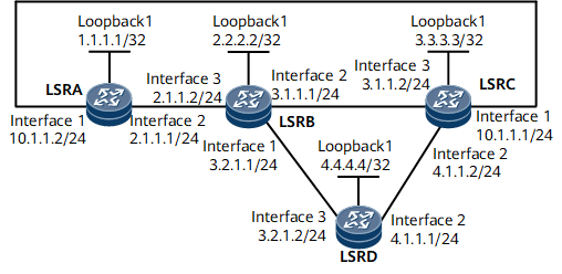
On the network shown in Figure 1, a primary CR-LSP is established over an explicit path LSRA -> LSRB -> LSRC. Bypass CR-LSPs need to be established on the ingress LSRA and the transit node LSRB respectively. These bypass CR-LSPs are required to provide bandwidth protection. A node protection tunnel is a bypass tunnel that originates from LSRA's inbound interface, terminates at LSRC's outbound interface, and passes through the intermediate LSRB. A link protection tunnel is a bypass tunnel that originates from LSRB's outbound interface, terminates at LSRC's inbound interface, and passes through the intermediate LSRD or is a direct link between LSRB's outbound interface and LSRC's inbound interface.
Configuration Roadmap
The configuration roadmap is as follows:
Configure a primary CR-LSP and enable MPLS Auto FRR in the MPLS and tunnel interface views.
Set the protected bandwidth and priorities for the bypass CR-LSP in the tunnel interface view.
Data Preparation
To complete the configuration, you need the following data:
OSPF process ID and OSPF area ID for every node
Path for the primary CR-LSP
Tunnel interface number, source and destination IP addresses of the primary tunnel, tunnel ID, RSVP-TE signaling protocol, and tunnel bandwidth
Procedure
- Assign an IP address and its mask to every interface.
Assign an IP address and its mask to every physical interface and configure a loopback interface address as an LSR ID on every node shown in Figure 1. For configuration details, see Configuration Files in this section.
- Configure OSPF to advertise every network segment route and host route.
Configure OSPF on all nodes to advertise host routes. For configuration details, see Configuration Files in this section.
After completing the configurations, run the display ip routing-table command on every node. All nodes have learned routes from one another.
- Configure basic MPLS functions and enable MPLS TE, RSVP-TE, and CSPF.
# Configure LSRA.
[*LSRA] mpls lsr-id 1.1.1.1
[*LSRA] mpls
[*LSRA-mpls] mpls te
[*LSRA-mpls] mpls rsvp-te
[*LSRA-mpls] mpls te cspf
[*LSRA-mpls] quit
[*LSRA] interface gigabitethernet 0/1/8
[*LSRA-GigabitEthernet0/1/8] mpls
[*LSRA-GigabitEthernet0/1/8] mpls te
[*LSRA-GigabitEthernet0/1/8] mpls rsvp-te
[*LSRA-GigabitEthernet0/1/8] quit
[*LSRA] interface gigabitethernet 0/1/0
[*LSRA-GigabitEthernet0/1/0] mpls
[*LSRA-GigabitEthernet0/1/0] mpls te
[*LSRA-GigabitEthernet0/1/0] mpls rsvp-te
[*LSRA-GigabitEthernet0/1/0] commit
[~LSRA-GigabitEthernet0/1/0] quit

Repeat this step for LSRB, LSRC, and LSRD. For configuration details, see Configuration Files in this section.
- Configure OSPF TE.
# Configure LSRA.
[~LSRA] ospf
[~LSRA-ospf-1] opaque-capability enable
[*LSRA-ospf-1] area 0
[*LSRA-ospf-1-area-0.0.0.0] mpls-te enable
[*LSRA-ospf-1-area-0.0.0.0] commit
[~LSRA-ospf-1-area-0.0.0.0] quit
[~LSRA-ospf-1] quit
Repeat this step for LSRB, LSRC, and LSRD. For configuration details, see Configuration Files in this section.
- Configure an explicit path for the primary CR-LSP.
[~LSRA] explicit-path master
[*LSRA-explicit-path-master] next hop 2.1.1.1
[*LSRA-explicit-path-master] next hop 3.1.1.1
[*LSRA-explicit-path-master] commit
- Configure TE Auto FRR.
# Configure LSRA.
[~LSRA] mpls
[~LSRA-mpls] mpls te auto-frr
[*LSRA-mpls] commit
# Configure LSRB.
[~LSRB] mpls
[~LSRB-mpls] mpls te auto-frr
[*LSRB-mpls] commit
- Configure a primary tunnel.
[~LSRA] interface tunnel2
[*LSRA-Tunnel2] ip address unnumbered interface loopBack1
[*LSRA-Tunnel2] tunnel-protocol mpls te
[*LSRA-Tunnel2] destination 3.3.3.3
[*LSRA-Tunnel2] mpls te tunnel-id 200
[*LSRA-Tunnel2] mpls te record-route label
[*LSRA-Tunnel2] mpls te path explicit-path master
[*LSRA-Tunnel2] mpls te bandwidth ct0 400
[*LSRA-Tunnel2] mpls te priority 4 3
[*LSRA-Tunnel2] mpls te fast-reroute bandwidth
[*LSRA-Tunnel2] mpls te bypass-attributes bandwidth 200 priority 5 4
[*LSRA-Tunnel2] commit
[~LSRA-Tunnel2] quit
- Verify the configuration.
Run the display mpls te tunnel name Tunnel2 verbose command on LSRA. Information about the primary and bypass CR-LSPs is displayed.
[~LSRA] display mpls te tunnel name Tunnel2 verbose
    No                      :  1
    Tunnel-Name             :  Tunnel2
    Tunnel Interface Name   :  Tunnel2
    TunnelIndex             :  -
    Session ID              :  200         LSP ID            :  164
    LSR Role                :  Ingress
    Ingress LSR ID          :  1.1.1.1
    Egress LSR ID           :  3.3.3.3
    In-Interface            :  -
    Out-Interface           :  GE0/1/8
    Sign-Protocol           :  RSVP TE     Resv Style        :  SE
    IncludeAnyAff           :  0x0         ExcludeAnyAff     :  0x0
    IncludeAllAff           :  0x0
    ER-Hop Table Index      :  1           AR-Hop Table Index:  674
    C-Hop Table Index       :  579
    PrevTunnelIndexInSession:  -           NextTunnelIndexInSession:  -
    PSB Handle              :  -
    Created Time            :  2015-01-28 11:10:32
    RSVP LSP Type           :  -
    --------------------------------
              DS-TE Information
    --------------------------------
    Bandwidth Reserved Flag :  Reserved
    CT0 Bandwidth(Kbit/sec) :  400         CT1 Bandwidth(Kbit/sec):  0
    CT2 Bandwidth(Kbit/sec) :  0           CT3 Bandwidth(Kbit/sec):  0
    CT4 Bandwidth(Kbit/sec) :  0           CT5 Bandwidth(Kbit/sec):  0
    CT6 Bandwidth(Kbit/sec) :  0           CT7 Bandwidth(Kbit/sec):  0
    Setup-Priority          :  4           Hold-Priority          :  3
    --------------------------------
                FRR Information
    --------------------------------
    Primary LSP Info
    Bypass In Use           :  Not Used
    Bypass Tunnel Id        :  32866
    BypassTunnel            :  Tunnel Index[AutoTunnel32866], InnerLabel[3]
    Bypass LSP ID           :  165         FrrNextHop        :  10.1.1.1
    ReferAutoBypassHandle   :  -
    FrrPrevTunnelTableIndex :  -           FrrNextTunnelTableIndex:  -
    Bypass Attribute
    Setup Priority          :  5           Hold Priority     :  4
    HopLimit                :  32          Bandwidth         :  200
    IncludeAnyGroup         :  0           ExcludeAnyGroup   :  0
    IncludeAllGroup         :  0
    Bypass Unbound Bandwidth Info(Kbit/sec)
    CT0 Unbound Bandwidth   :  -           CT1 Unbound Bandwidth:  -
    CT2 Unbound Bandwidth   :  -           CT3 Unbound Bandwidth:  -
    CT4 Unbound Bandwidth   :  -           CT5 Unbound Bandwidth:  -
    CT6 Unbound Bandwidth   :  -           CT7 Unbound Bandwidth:  -
    --------------------------------
               BFD Information
    --------------------------------
    NextSessionTunnelIndex  :  -           PrevSessionTunnelIndex:  -
    NextLspId               :  -           PrevLspId         :  -
The primary CR-LSP has been bound to a bypass CR-LSP named AutoTunnel32866.
Run the display mpls te tunnel-interface auto-bypass-tunnel command. Detailed information about the automatic bypass CR-LSP is displayed. Its bandwidth, and setup and holding priorities are the same as bypass attributes in the primary CR-LSP information.
[~LSRA] display mpls te tunnel-interface auto-bypass-tunnel AutoTunnel32866
    Tunnel Name       : AutoTunnel32866
    Signalled Tunnel Name: -
    Tunnel State Desc : CR-LSP is Up
    Tunnel Attributes   :
    Active LSP          : Primary LSP
    Traffic Switch      : -
    Session ID          : 32866
    Ingress LSR ID      : 1.1.1.1               Egress LSR ID: 3.3.3.3
    Admin State         : UP                    Oper State   : UP
    Signaling Protocol  : RSVP
    FTid                : 130
    Tie-Breaking Policy : None                  Metric Type  : None
    Bfd Cap             : None
    Reopt               : Disabled              Reopt Freq   : -
    Inter-area Reopt    : Disabled
    Auto BW             : Disabled              Threshold    : -
    Current Collected BW: -                     Auto BW Freq : -
    Min BW              : -                     Max BW       : -
    Offload             : Disabled              Offload Freq : -
    Low Value           : -                     High Value   : -
    Readjust Value      : -
    Offload Explicit Path Name: -
    Tunnel Group        : Primary
    Interfaces Protected: GigabitEthernet0/1/8
    Excluded IP Address : 2.1.1.1
                          2.1.1.2
                          2.2.2.2
    Referred LSP Count  : 1
    Primary Tunnel      : -                     Pri Tunn Sum : -
    Backup Tunnel       : -
    Group Status        : Down                  Oam Status   : None
    IPTN InLabel        : -
    BackUp LSP Type     : None                  BestEffort   : Disabled
    Secondary HopLimit  : -
    BestEffort HopLimit  : -
    Secondary Explicit Path Name: -
    Secondary Affinity Prop/Mask: 0x0/0x0
    BestEffort Affinity Prop/Mask: 0x0/0x0
    IsConfigLspConstraint: -
    Hot-Standby Revertive Mode:  Revertive
    Hot-Standby Overlap-path:  Disabled
    Hot-Standby Switch State:  CLEAR
    Bit Error Detection:  Disabled
    Bit Error Detection Switch Threshold:  -
    Bit Error Detection Resume Threshold:  -
    Ip-Prefix Name    : -
    P2p-Template Name : -
    PCE Delegate      : No                    LSP Control Status : Local control
    Path Verification : --
    Entropy Label     : None
    Associated Tunnel Group ID: -             Associated Tunnel Group Type: -
    Auto BW Remain Time : 200 s               Reopt Remain Time  : 100 s
    Metric Inherit IGP : None
    Binding Sid       : -                     Reverse Binding Sid : -
    Self-Ping         : Disable               Self-Ping Duration : 1800 sec
    FRR Attr Source   : -                     Is FRR degrade down : No

    Primary LSP ID      : 1.1.1.1:165
    LSP State           : UP                    LSP Type     : Primary
    Setup Priority      : 5                     Hold Priority: 4
    IncludeAll          : 0x0
    IncludeAny          : 0x0
    ExcludeAny          : 0x0
    Affinity Prop/Mask  : 0x0/0x0               Resv Style   :  SE
    Configured Bandwidth Information:
    CT0 Bandwidth(Kbit/sec): 200             CT1 Bandwidth(Kbit/sec): 0
    CT2 Bandwidth(Kbit/sec): 0               CT3 Bandwidth(Kbit/sec): 0
    CT4 Bandwidth(Kbit/sec): 0               CT5 Bandwidth(Kbit/sec): 0
    CT6 Bandwidth(Kbit/sec): 0               CT7 Bandwidth(Kbit/sec): 0
    Actual Bandwidth Information:
    CT0 Bandwidth(Kbit/sec): 200             CT1 Bandwidth(Kbit/sec): 0
    CT2 Bandwidth(Kbit/sec): 0               CT3 Bandwidth(Kbit/sec): 0
    CT4 Bandwidth(Kbit/sec): 0               CT5 Bandwidth(Kbit/sec): 0
    CT6 Bandwidth(Kbit/sec): 0               CT7 Bandwidth(Kbit/sec): 0
    Explicit Path Name  : master                           Hop Limit: -
    Record Route        : Enabled               Record Label : Enabled
    Route Pinning       : Disabled
    FRR Flag            : Disabled
    IdleTime Remain     : -
    BFD Status          : -
    Soft Preemption     : Disabled
    Reroute Flag        : Disabled
    Pce Flag            : Normal
    Path Setup Type     : EXPLICIT
    Create Modify LSP Reason: -
    Self-Ping Status    : -
The automatic bypass CR-LSP protects traffic on GE 0/1/8, the outbound interface of the primary CR-LSP, not other three interfaces. The bandwidth is 200 kbit/s, and the setup and holding priority values are 5 and 4, respectively.
Run the display mpls te tunnel path command on LSRA. The bypass CR-LSP is providing both node and bandwidth protection for the primary CR-LSP.
[~LSRA] display mpls te tunnel path
 Tunnel Interface Name : Tunnel2
 Lsp ID : 1.1.1.1 :200 :164
 Hop Information
  Hop 0   2.1.1.1 Local-Protection available | bandwidth | node
  Hop 1   2.1.1.2 Label 32846
  Hop 2   2.2.2.2 Label 32846
  Hop 3   3.1.1.1 Local-Protection available | bandwidth
  Hop 4   3.1.1.2 Label 3
  Hop 5   3.3.3.3 Label 3

 Tunnel Interface Name : AutoTunnel32866
 Lsp ID : 1.1.1.1 :32866 :165
 Hop Information
  Hop 0   10.1.1.2
  Hop 1   10.1.1.1 Label 3
  Hop 2   3.3.3.3 Label 3
Run the display mpls te tunnel name Tunnel2 verbose command on the transit LSRB. Information about the primary and bypass CR-LSPs is displayed.
[~LSRB] display mpls te tunnel name Tunnel2 verbose
    No                      :  1
    Tunnel-Name             :  Tunnel2
    Tunnel Interface Name   :  -
    TunnelIndex             :  -
    Session ID              :  200         LSP ID            :  164
    LSR Role                :  Transit
    Ingress LSR ID          :  1.1.1.1
    Egress LSR ID           :  3.3.3.3
    In-Interface            :  GE0/1/16
    Out-Interface           :  GE0/1/8
    Sign-Protocol           :  RSVP TE     Resv Style        :  SE
    IncludeAnyAff           :  0x0         ExcludeAnyAff     :  0x0
    IncludeAllAff           :  0x0
    ER-Hop Table Index      :  -           AR-Hop Table Index:  -
    C-Hop Table Index       :  -
    PrevTunnelIndexInSession:  -           NextTunnelIndexInSession:  -
    PSB Handle              :  -
    Created Time            :  2015-01-28 11:10:32
    RSVP LSP Type           :  -
    --------------------------------
              DS-TE Information
    --------------------------------
    Bandwidth Reserved Flag :  Reserved
    CT0 Bandwidth(Kbit/sec) :  400         CT1 Bandwidth(Kbit/sec):  0
    CT2 Bandwidth(Kbit/sec) :  0           CT3 Bandwidth(Kbit/sec):  0
    CT4 Bandwidth(Kbit/sec) :  0           CT5 Bandwidth(Kbit/sec):  0
    CT6 Bandwidth(Kbit/sec) :  0           CT7 Bandwidth(Kbit/sec):  0
    Setup-Priority          :  4           Hold-Priority          :  3
    --------------------------------
                FRR Information
    --------------------------------
    Primary LSP Info
    Bypass In Use           :  Not Used
    Bypass Tunnel Id        :  32865
    BypassTunnel            :  Tunnel Index[AutoTunnel32865], InnerLabel[3]
    Bypass LSP ID           :  6           FrrNextHop        :  4.1.1.2
    ReferAutoBypassHandle   :  -
    FrrPrevTunnelTableIndex :  -           FrrNextTunnelTableIndex:  -
    Bypass Attribute
    Setup Priority          :  5           Hold Priority     :  4
    HopLimit                :  32          Bandwidth         :  200
    IncludeAnyGroup         :  0           ExcludeAnyGroup   :  0
    IncludeAllGroup         :  0
    Bypass Unbound Bandwidth Info(Kbit/sec)
    CT0 Unbound Bandwidth   :  -           CT1 Unbound Bandwidth:  -
    CT2 Unbound Bandwidth   :  -           CT3 Unbound Bandwidth:  -
    CT4 Unbound Bandwidth   :  -           CT5 Unbound Bandwidth:  -
    CT6 Unbound Bandwidth   :  -           CT7 Unbound Bandwidth:  -
    --------------------------------
               BFD Information
    --------------------------------
    NextSessionTunnelIndex  :  -           PrevSessionTunnelIndex:  -
    NextLspId               :  -           PrevLspId         :  -
The primary CR-LSP has been bound to a bypass CR-LSP named AutoTunnel32865.
Run the display mpls te tunnel-interface auto-bypass-tunnel command. Detailed information about the automatic bypass CR-LSP is displayed. Its bandwidth, and setup and holding priorities are the same as bypass attributes in the primary CR-LSP information.
[~LSRB] display mpls te tunnel-interface auto-bypass-tunnel AutoTunnel32865
    Tunnel Name       : AutoTunnel32865
    Signalled Tunnel Name: -
    Tunnel State Desc : CR-LSP is Up
    Tunnel Attributes   :
    Active LSP          : Primary LSP
    Traffic Switch      : -
    Session ID          : 32865
    Ingress LSR ID      : 2.2.2.2               Egress LSR ID: 3.3.3.3
    Admin State         : UP                    Oper State   : UP
    Signaling Protocol  : RSVP
    FTid                : 97
    Tie-Breaking Policy : None                  Metric Type  : None
    Bfd Cap             : None
    Reopt               : Disabled              Reopt Freq   : -
    Inter-area Reopt    : Disabled
    Auto BW             : Disabled              Threshold    : -
    Current Collected BW: -                     Auto BW Freq : -
    Min BW              : -                     Max BW       : -
    Offload             : Disabled              Offload Freq : -
    Low Value           : -                     High Value   : -
    Readjust Value      : -
    Offload Explicit Path Name: -
    Tunnel Group        : Primary
    Interfaces Protected: GigabitEthernet0/1/8
    Excluded IP Address : 3.1.1.1
                          3.1.1.2
    Referred LSP Count  : 1
    Primary Tunnel      : -                     Pri Tunn Sum : -
    Backup Tunnel       : -
    Group Status        : Down                  Oam Status   : None
    IPTN InLabel        : -
    BackUp LSP Type     : None                  BestEffort   : Disabled
    Secondary HopLimit  : -
    BestEffort HopLimit  : -
    Secondary Explicit Path Name: -
    Secondary Affinity Prop/Mask: 0x0/0x0
    BestEffort Affinity Prop/Mask: 0x0/0x0
    IsConfigLspConstraint: -
    Hot-Standby Revertive Mode:  Revertive
    Hot-Standby Overlap-path:  Disabled
    Hot-Standby Switch State:  CLEAR
    Bit Error Detection:  Disabled
    Bit Error Detection Switch Threshold:  -
    Bit Error Detection Resume Threshold:  -
    Ip-Prefix Name    : -
    P2p-Template Name : -
    PCE Delegate      : No                    LSP Control Status : Local control
    Path Verification : -
    Entropy Label     : None
    Associated Tunnel Group ID: -             Associated Tunnel Group Type: -
    Auto BW Remain Time : 200 s               Reopt Remain Time  : 100 s
    Metric Inherit IGP : None
    Binding Sid       : -                     Reverse Binding Sid : -
    Self-Ping         : Disable               Self-Ping Duration : 1800 sec
    FRR Attr Source   : -                     Is FRR degrade down : No

    Primary LSP ID      : 2.2.2.2:6
    LSP State           : UP                    LSP Type     : Primary
    Setup Priority      : 5                     Hold Priority: 4
    IncludeAll          : 0x0
    IncludeAny          : 0x0
    ExcludeAny          : 0x0
    Affinity Prop/Mask  : 0x0/0x0               Resv Style   :  SE
    Configured Bandwidth Information:
    CT0 Bandwidth(Kbit/sec): 200             CT1 Bandwidth(Kbit/sec): 0
    CT2 Bandwidth(Kbit/sec): 0               CT3 Bandwidth(Kbit/sec): 0
    CT4 Bandwidth(Kbit/sec): 0               CT5 Bandwidth(Kbit/sec): 0
    CT6 Bandwidth(Kbit/sec): 0               CT7 Bandwidth(Kbit/sec): 0
    Actual Bandwidth Information:
    CT0 Bandwidth(Kbit/sec): 200             CT1 Bandwidth(Kbit/sec): 0
    CT2 Bandwidth(Kbit/sec): 0               CT3 Bandwidth(Kbit/sec): 0
    CT4 Bandwidth(Kbit/sec): 0               CT5 Bandwidth(Kbit/sec): 0
    CT6 Bandwidth(Kbit/sec): 0               CT7 Bandwidth(Kbit/sec): 0
    Explicit Path Name  : -                                Hop Limit: -
    Record Route        : Enabled               Record Label : Enabled
    Route Pinning       : Disabled
    FRR Flag            : Disabled
    IdleTime Remain     : -
    BFD Status          : -
    Soft Preemption     : Disabled
    Reroute Flag        : Disabled
    Pce Flag            : Normal
    Path Setup Type     : CSPF
    Create Modify LSP Reason: -
    Self-Ping Status    : -
The automatic bypass CR-LSP protects traffic on GE 0/1/8, the outbound interface of the primary CR-LSP. The bandwidth is 200 kbit/s, and the setup and holding priority values are 5 and 4, respectively.
Run the display mpls te tunnel path command on LSRB. Information about the path of both primary CR-LSP and automatic bypass CR-LSP is displayed.
[~LSRB] display mpls te tunnel path
 Tunnel Interface Name : Tunnel2
 Lsp ID : 1.1.1.1 :200 :164
 Hop Information
  Hop 0   1.1.1.1
  Hop 1   2.1.1.1 Local-Protection available | bandwidth | node
  Hop 2   2.1.1.2 Label 32846
  Hop 3   2.2.2.2 Label 32846
  Hop 4   3.1.1.1 Local-Protection available | bandwidth
  Hop 5   3.1.1.2 Label 3
  Hop 6   3.3.3.3 Label 3

 Tunnel Interface Name : AutoTunnel32865
 Lsp ID : 2.2.2.2 :32865 :6
 Hop Information
  Hop 0   3.2.1.1
  Hop 1   3.2.1.2 Label 32839
  Hop 2   4.4.4.4 Label 32839
  Hop 3   4.1.1.1
  Hop 4   4.1.1.2 Label 3
  Hop 5   3.3.3.3 Label 3
Configuration Files
LSRA configuration file
#
sysname LSR A
#
mpls lsr-id 1.1.1.1
#
mpls
 mpls te
 mpls te auto-frr
 mpls te cspf
 mpls rsvp-te
#
explicit-path master
 next hop 2.1.1.1
 next hop 3.1.1.1
#
ospf 1
 opaque-capability enable
 area 0.0.0.0
  mpls-te enable
  network 10.1.1.0 0.0.0.255
  network 2.1.1.0 0.0.0.255
  network 1.1.1.1 0.0.0.0
#
interface GigabitEthernet0/1/0
 undo shutdown
 ip address 10.1.1.2 255.255.255.0
 mpls
 mpls te
 mpls rsvp-te
#
interface GigabitEthernet0/1/8
 undo shutdown
 ip address 2.1.1.1 255.255.255.0
 mpls
 mpls te
 mpls rsvp-te
#
interface LoopBack1
 ip address 1.1.1.1 255.255.255.255
#
interface Tunnel2
 ip address unnumbered interface LoopBack1
 tunnel-protocol mpls te
 destination 3.3.3.3
 mpls te tunnel-id 200
 mpls te record-route label
 mpls te priority 4 3
 mpls te bandwidth ct0 400
 mpls te path explicit-path master
 mpls te fast-reroute bandwidth
 mpls te bypass-attributes bandwidth 200 priority 5 4
#
return
LSRB configuration file
#
sysname LSRB
#
mpls lsr-id 2.2.2.2
#
mpls
 mpls te
 mpls te auto-frr
 mpls te cspf
 mpls rsvp-te
#
ospf 1
 opaque-capability enable
 area 0.0.0.0
  mpls-te enable
  network 3.1.1.0 0.0.0.255
  network 3.2.1.0 0.0.0.255
  network 2.1.1.0 0.0.0.255
  network 2.2.2.2 0.0.0.0
#
interface GigabitEthernet0/1/0
 undo shutdown
 ip address 3.2.1.1 255.255.255.0
 mpls
 mpls te
 mpls rsvp-te
#
interface GigabitEthernet0/1/8
 undo shutdown
 ip address 3.1.1.1 255.255.255.0
 mpls
 mpls te
 mpls rsvp-te
#
interface GigabitEthernet0/1/16
 undo shutdown
 ip address 2.1.1.2 255.255.255.0
 mpls
 mpls te
 mpls rsvp-te
#
interface LoopBack1
 ip address 2.2.2.2 255.255.255.255
#
return
LSRC configuration file
#
sysname LSRC
#
mpls lsr-id 3.3.3.3
#
mpls
 mpls te
 mpls rsvp-te
#
ospf 1
 opaque-capability enable
 area 0.0.0.0
  mpls-te enable
  network 10.1.1.0 0.0.0.255
  network 3.1.1.0 0.0.0.255
  network 4.1.1.0 0.0.0.255
  network 3.3.3.3 0.0.0.0
#
interface GigabitEthernet0/1/0
 undo shutdown
 ip address 10.1.1.1 255.255.255.0
 mpls
 mpls te
 mpls rsvp-te
#
interface GigabitEthernet0/1/8
 undo shutdown
 ip address 4.1.1.2 255.255.255.0
 mpls
 mpls te
 mpls rsvp-te
#
interface GigabitEthernet0/1/16
 undo shutdown
 ip address 3.1.1.2 255.255.255.0
 mpls
 mpls te
 mpls rsvp-te
#
interface LoopBack1
 ip address 3.3.3.3 255.255.255.255
#
return
LSRD configuration file
#
sysname LSRD
#
mpls lsr-id 4.4.4.4
#
mpls
 mpls te
 mpls rsvp-te
#
ospf 1
 opaque-capability enable
 area 0.0.0.0
  mpls-te enable
  network 3.2.1.0 0.0.0.255
  network 4.1.1.0 0.0.0.255
  network 4.4.4.4 0.0.0.0
#
interface GigabitEthernet0/1/8
 undo shutdown
 mpls
 ip address 4.1.1.1 255.255.255.0
 mpls te
 mpls rsvp-te
#
interface GigabitEthernet0/1/16
 undo shutdown
 ip address 3.2.1.2 255.255.255.0
 mpls
 mpls te
 mpls rsvp-te
#
interface LoopBack1
 ip address 4.4.4.4 255.255.255.255
#
Return