Example for Configuring MPLS Detour FRR
This section provides an example for configuring MPLS detour FRR on an RSVP-TE tunnel.
Networking Requirements
Traffic engineering (TE) fast reroute (FRR) provides local link and node protection for MPLS TE tunnels. If a link or node fails, traffic is rapidly switched to a backup path, which minimizes traffic loss. TE FRR is working in facility or one-to-one backup mode. TE FRR in one-to-one backup mode is also called MPLS detour FRR. MPLS detour FRR automatically creates a detour LSP on each eligible node along primary CR-LSP to protect downstream links or nodes. This mode is easy to configure, eliminates manual network planning, and provides flexibility on a complex network.
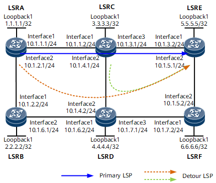
Figure 1 shows a primary RSVP-TE tunnel along the path LSRA -> LSRC -> LSRE. To improve tunnel reliability, MPLS detour FRR must be configured.

For information about how to configure TE FRR in facility backup mode, see Example for Configuring MPLS TE Manual FRR and Example for Configuring MPLS TE Auto FRR.
Configuration Notes
The facility backup and one-to-one backup modes are mutually exclusive on the same TE tunnel interface. If both modes are configured, the latest configured mode overrides the previous one.
The shared explicit (SE) style must be used for the MPLS detour FRR-enabled tunnel.
CSPF must be enabled on each node along both the primary and backup RSVP-TE tunnels.
Configuration Roadmap
The configuration roadmap is as follows:
Configure an RSVP-TE tunnel.
Enable MPLS detour FRR on an RSVP-TE tunnel interface.
Data Preparation
To complete the configuration, you need the following data:
IP addresses of interfaces
IGP protocol (IS-IS), process ID (1), system ID (converted using loopback1 address), and IS-IS level (level-2)
LSR ID (loopback interface address) of every MPLS node
Tunnel interface name (Tunnel1), tunnel IP address (loopback interface IP address), tunnel ID (100), and destination IP address (5.5.5.5)
Procedure
- Assign an IP address and a mask to each interface.
Assign an IP address to each interface and create a loopback interface on each node. For configuration details, see Configuration Files in this section.
- Configure IS-IS to advertise the route to each network segment to which each interface is connected and to advertise the host route to each loopback address that is used as an LSR ID.
Configure IS-IS on each node to implement network layer connectivity. For configuration details, see Configuration Files in this section.
- Enable MPLS, MPLS TE, MPLS RSVP-TE, and CSPF globally on each node.
# Configure LSRA.
<LSRA> system-view
[~LSRA] mpls lsr-id 1.1.1.1
[*LSRA] mpls
[*LSRA-mpls] mpls te
[*LSRA-mpls] mpls rsvp-te
[*LSRA-mpls] mpls te cspf
[*LSRA-mpls] commit
[~LSRA-mpls] quit
Repeat this step for LSRB, LSRC, LSRD, LSRE, and LSRF. For configuration details, see Configuration Files in this section.
- Enable IGP TE on each node.
# Configure LSRA.
[~LSRA] isis 1
[~LSRA-isis-1] cost-style wide
[*LSRA-isis-1] traffic-eng level-2
[*LSRA-isis-1] commit
[~LSRA-isis-1] quit
Repeat this step for LSRB, LSRC, LSRD, LSRE, and LSRF. For configuration details, see Configuration Files in this section.
- Enable RSVP-TE on interfaces of each node.
# Configure LSRA.
[~LSRA] interface gigabitethernet 0/1/1
[~LSRA-GigabitEthernet0/1/1] mpls
[*LSRA-GigabitEthernet0/1/1] mpls te
[*LSRA-GigabitEthernet0/1/1] mpls rsvp-te
[*LSRA-GigabitEthernet0/1/1] commit
[~LSRA-GigabitEthernet0/1/1] quit
[~LSRA] interface gigabitethernet 0/1/2
[~LSRA-GigabitEthernet0/1/2] mpls
[*LSRA-GigabitEthernet0/1/2] mpls te
[*LSRA-GigabitEthernet0/1/2] mpls rsvp-te
[*LSRA-GigabitEthernet0/1/2] commit
[~LSRA-GigabitEthernet0/1/2] quit
Repeat this step for LSRB, LSRC, LSRD, LSRE, and LSRF. For configuration details, see Configuration Files in this section.
- Configure an RSVP-TE tunnel interface on LSRA (ingress).
# Configure LSRA.
[~LSRA] interface tunnel 1
[*LSRA-Tunnel1] ip address unnumbered interface loopback 1
[*LSRA-Tunnel1] tunnel-protocol mpls te
[*LSRA-Tunnel1] mpls te tunnel-id 100
[*LSRA-Tunnel1] destination 5.5.5.5
- Enable MPLS detour FRR on an RSVP-TE tunnel interface.
# Configure LSRA.
[*LSRA-Tunnel1] mpls te detour
[*LSRA-Tunnel1] commit
[~LSRA-Tunnel1] quit
- Verify the configuration.After completing the configurations, run the display mpls te tunnel command on LSRA to view detour LSP information.
[~LSRA] display mpls te tunnel
* means the LSP is detour LSP
-------------------------------------------------------------------------------
Ingress LsrId   Destination     LSPID In/OutLabel     R Tunnel-name
-------------------------------------------------------------------------------
1.1.1.1         5.5.5.5         25    -/32832         I Tunnel1
1.1.1.1         5.5.5.5         25   *-/32831         I Tunnel1
-------------------------------------------------------------------------------
R: Role, I: Ingress, T: Transit, E: Egress
Run the display mpls te tunnel path command on LSRA to view the primary CR-LSP and detour LSP information. The command output shows that a detour LSP has been established to provide node protection on LSRA, and another detour LSP has been established to provide link protection on LSRC.[~LSRA] display mpls te tunnel path Tunnel Interface Name : Tunnel1 Lsp ID : 1.1.1.1 :100 :25 Hop Information Hop 0 10.1.1.1 Local-Protection available | node Hop 1 10.1.1.2 Label 32832 Hop 2 3.3.3.3 Label 32832 Hop 3 10.1.3.1 Local-Protection available Hop 4 10.1.3.2 Label 3 Hop 5 5.5.5.5 Label 3 Tunnel Interface Name : Tunnel1 Lsp ID : 1.1.1.1 :100 :25 Detour Lsp PLR ID :10.1.2.1 Hop Information Hop 0 10.1.2.1 Hop 1 10.1.2.2 Label 32831 Hop 2 2.2.2.2 Label 32831 Hop 3 10.1.6.1 Hop 4 10.1.6.2 Label 32832 Hop 5 4.4.4.4 Label 32832 Hop 6 10.1.7.1 Hop 7 10.1.7.2 Label 32831 Hop 8 6.6.6.6 Label 32831 Hop 9 10.1.5.2 Hop 10 10.1.5.1 Label 3 Hop 11 5.5.5.5 Label 3
Configuration Files
LSRA configuration file
#
sysname LSRA
#
mpls lsr-id 1.1.1.1
#
mpls
 mpls te
 mpls rsvp-te
 mpls te cspf
#
isis 1
 is-level level-2
 cost-style wide
 network-entity 10.0001.0010.0100.1001.00
 traffic-eng level-2
#
interface GigabitEthernet0/1/1
 undo shutdown
 ip address 10.1.1.1 255.255.255.0
 isis enable 1
 mpls
 mpls te
 mpls rsvp-te
#
interface GigabitEthernet0/1/2
 undo shutdown
 ip address 10.1.2.1 255.255.255.0
 isis enable 1
 mpls
 mpls te
 mpls rsvp-te
#
interface LoopBack1
 ip address 1.1.1.1 255.255.255.255
 isis enable 1
#
interface Tunnel1
 ip address unnumbered interface LoopBack1
 tunnel-protocol mpls te
 destination 5.5.5.5
 mpls te record-route label
 mpls te detour
 mpls te tunnel-id 100
#
return
LSRB configuration file
#
sysname LSRB
#
mpls lsr-id 2.2.2.2
#
mpls
 mpls te
 mpls rsvp-te
 mpls te cspf
#
isis 1
 is-level level-2
 cost-style wide
 network-entity 10.0001.0020.0200.2002.00
 traffic-eng level-2
#
interface GigabitEthernet0/1/1
 undo shutdown
 ip address 10.1.2.2 255.255.255.0
 isis enable 1
 mpls
 mpls te
 mpls rsvp-te
#
interface GigabitEthernet0/1/2
 undo shutdown
 ip address 10.1.6.1 255.255.255.0
 isis enable 1
 mpls
 mpls te
 mpls rsvp-te
#
interface LoopBack1
 ip address 2.2.2.2 255.255.255.255
 isis enable 1
#
return
LSRC configuration file
#
sysname LSRC
#
mpls lsr-id 3.3.3.3
#
mpls
 mpls te
 mpls rsvp-te
 mpls te cspf
#
isis 1
 is-level level-2
 cost-style wide
 network-entity 10.0001.0030.0300.3003.00
 traffic-eng level-2
#
interface GigabitEthernet0/1/1
 undo shutdown
 ip address 10.1.1.2 255.255.255.0
 isis enable 1
 mpls
 mpls te
 mpls rsvp-te
#
interface GigabitEthernet0/1/2
 undo shutdown
 ip address 10.1.4.1 255.255.255.0
 isis enable 1
 mpls
 mpls te
 mpls rsvp-te
#
interface GigabitEthernet0/1/3
 undo shutdown
 ip address 10.1.3.1 255.255.255.0
 isis enable 1
 mpls
 mpls te
 mpls rsvp-te
#
interface LoopBack1
 ip address 3.3.3.3 255.255.255.255
 isis enable 1
#
return
LSRD configuration file
#
sysname LSRD
#
mpls lsr-id 4.4.4.4
#
mpls
 mpls te
 mpls rsvp-te
 mpls te cspf
#
isis 1
 is-level level-2
 cost-style wide
 network-entity 10.0001.0040.0400.4004.00
 traffic-eng level-2
#
interface GigabitEthernet0/1/1
 undo shutdown
 ip address 10.1.6.2 255.255.255.0
 isis enable 1
 mpls
 mpls te
 mpls rsvp-te
#
interface GigabitEthernet0/1/2
 undo shutdown
 ip address 10.1.4.2 255.255.255.0
 isis enable 1
 mpls
 mpls te
 mpls rsvp-te
#
interface GigabitEthernet0/1/3
 undo shutdown
 ip address 10.1.7.1 255.255.255.0
 isis enable 1
 mpls
 mpls te
 mpls rsvp-te
#
interface LoopBack1
 ip address 4.4.4.4 255.255.255.255
 isis enable 1
#
return
LSRE configuration file
#
sysname LSRE
#
mpls lsr-id 5.5.5.5
#
mpls
 mpls te
 mpls rsvp-te
 mpls te cspf
#
isis 1
 is-level level-2
 cost-style wide
 network-entity 10.0001.0050.0500.5005.00
 traffic-eng level-2
#
interface GigabitEthernet0/1/1
 undo shutdown
 ip address 10.1.3.2 255.255.255.0
 isis enable 1
 mpls
 mpls te
 mpls rsvp-te
#
interface GigabitEthernet0/1/2
 undo shutdown
 ip address 10.1.5.1 255.255.255.0
 isis enable 1
 mpls
 mpls te
 mpls rsvp-te
#
interface LoopBack1
 ip address 5.5.5.5 255.255.255.255
 isis enable 1
#
return
LSRF configuration file
#
sysname LSRF
#
mpls lsr-id 6.6.6.6
#
mpls
 mpls te
 mpls rsvp-te
 mpls te cspf
#
isis 1
 is-level level-2
 cost-style wide
 network-entity 10.0001.0060.0600.6006.00
 traffic-eng level-2
#
interface GigabitEthernet0/1/2
 undo shutdown
 ip address 10.1.5.2 255.255.255.0
 isis enable 1
 mpls
 mpls te
 mpls rsvp-te
#
interface GigabitEthernet0/1/1
 undo shutdown
 ip address 10.1.7.2 255.255.255.0
 isis enable 1
 mpls
 mpls te
 mpls rsvp-te
#
interface LoopBack1
 ip address 6.6.6.6 255.255.255.255
 isis enable 1
#
return