Example for Configuring Static BFD for CR-LSP
By configuring static BFD for CR-LSP, enable a device to switch traffic to the backup CR-LSP if the primary CR-LSP fails. When the primary CR-LSP recovers, the traffic can switch back from the backup CR-LSP to the primary CR-LSP.
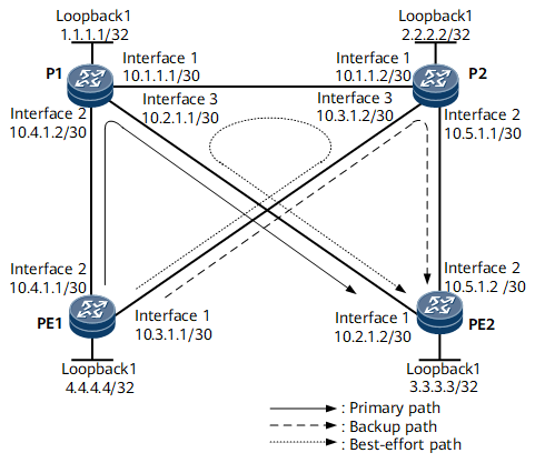
Networking Requirements
The primary CR-LSP is PE1 → P1 → PE2.
The backup CR-LSP is PE1 → P2 → PE2.
Two static BFD sessions are established to monitor the primary and backup CR-LSPs. After the configuration, the following objects are achieved:
If the primary CR-LSP fails, traffic switches to the backup CR-LSP.
If the primary CR-LSP recovers and the backup CR-LSP fails during the switchover time (15s), traffic switches back to the primary CR-LSP.
Configuration Roadmap
The configuration roadmap is as follows:
Configure CR-LSP hot standby.
- Configure reverse CR-LSPs for a BFD session.

A reverse CR-LSP must be established for each of the primary and hot-standby CR-LSPs.
On PE1, establish two BFD sessions and bind one to the primary CR-LSP and the other to the hot-standby CR-LSP; on PE2, establish two BFD sessions and bind both sessions to the IP link (PE2 → PE1).
Data Preparation
To complete the configuration, you need the following data:
Name of the BFD session
Local and remote discriminators of BFD sessions
Minimum intervals at which BFD packets are sent and received
Other data as described in Example for Configure a Hot-standby CR-LSP in HUAWEI NetEngine 8000 F Series Router Configuration Guide -MPLS
Procedure
- Configure CR-LSP hot standby.
For configuration details, see Example for Configure a Hot-standby CR-LSP in HUAWEI NetEngine 8000 F Series Router Configuration Guide - MPLS.
- Configure reverse CR-LSPs.
The reverse CR-LSP configuration on PE2 is similar to the forward CR-LSP configuration on PE1. For configuration details, see Configuration Files in this section.
- Configure BFD for CR-LSP.
# Establish BFD sessions between PE1 and PE2 to monitor the primary and backup CR-LSPs. Bind the BFD sessions on PE1 to the primary and backup CR-LSP and the BFD session on PE2 to the IP link. Set the minimum intervals at which BFD packets are sent and received to 100 milliseconds and the local BFD detection multiplier to 3.
# Configure PE1.
<HUAWEI> system-view
[~HUAWEI] sysname PE1
[*HUAWEI] commit
[*PE1] bfd
[*PE1-bfd] quit
[*PE1] bfd mainlsptope2 bind mpls-te interface tunnel 1 te-lsp
[*PE1-bfd-lsp-session-mainlsptope2] discriminator local 413
[*PE1-bfd-lsp-session-mainlsptope2] discriminator remote 314
[*PE1-bfd-lsp-session-mainlsptope2] min-tx-interval 100
[*PE1-bfd-lsp-session-mainlsptope2] min-rx-interval 100
[*PE1-bfd-lsp-session-mainlsptope2] process-pst
[*PE1-bfd-lsp-session-mainlsptope2] quit
[*PE1] bfd backuplsptope2 bind mpls-te interface tunnel 1 te-lsp backup
[*PE1-bfd-lsp-session-backuplsptope2] discriminator local 423
[*PE1-bfd-lsp-session-backuplsptope2] discriminator remote 324
[*PE1-bfd-lsp-session-backuplsptope2] min-tx-interval 100
[*PE1-bfd-lsp-session-backuplsptope2] min-rx-interval 100
[*PE1-bfd-lsp-session-backuplsptope2] process-pst
[*PE1-bfd-lsp-session-backuplsptope2] commit
[~PE1-bfd-lsp-session-backuplsptope2] quit
# Configure PE2.
<HUAWEI> system-view
[~HUAWEI] sysname PE2
[*HUAWEI] commit
[*PE2] bfd
[*PE2-bfd] quit
[*PE2] bfd mainlsptope2 bind mpls-te interface Tunnel2 te-lsp
[*PE2-bfd-lsp-session-mainlsptope2] discriminator local 314
[*PE2-bfd-lsp-session-mainlsptope2] discriminator remote 413
[*PE2-bfd-lsp-session-mainlsptope2] min-tx-interval 100
[*PE2-bfd-lsp-session-mainlsptope2] min-rx-interval 100
[*PE2-bfd-lsp-session-mainlsptope2] quit
[*PE2] bfd backuplsptope2 bind mpls-te interface Tunnel2 te-lsp backup
[*PE2-bfd-lsp-session-backuplsptope2] discriminator local 324
[*PE2-bfd-lsp-session-backuplsptope2] discriminator remote 423
[*PE2-bfd-lsp-session-backuplsptope2] min-tx-interval 100
[*PE2-bfd-lsp-session-backuplsptope2] min-rx-interval 100
[*PE2-bfd-lsp-session-backuplsptope2] commit
[*PE2-bfd-lsp-session-backuplsptope2] quit
# After completing the configuration, run the display bfd session discriminator local-discriminator-value command on PE1 and PE2. The status of BFD sessions is Up.
The following example uses the command output on PE1.
[~PE1] display bfd session discriminator 413
(w): State in WTR
(*): State is invalid
--------------------------------------------------------------------------------
Local Remote     PeerIpAddr      State     Type        InterfaceName
--------------------------------------------------------------------------------
413   314        3.3.3.3         Up        S_TE_LSP    Tunnel1
--------------------------------------------------------------------------------
--------------------------------------------------------------------------------
[~PE1] display bfd session discriminator 423
(w): State in WTR
(*): State is invalid
--------------------------------------------------------------------------------
Local Remote     PeerIpAddr      State     Type        InterfaceName
--------------------------------------------------------------------------------
423   324        3.3.3.3         Up        S_TE_LSP    Tunnel1
--------------------------------------------------------------------------------
- Verify the configuration.
Connect port 1 and port 2 on a tester to PE1 and PE2, respectively. Set correct label values. Inject MPLS traffic destined for port 2 into port 1. Write down the label setting in MPLS packets. After the cable to GE 0/1/8 on PE1 or GE 0/1/8 on P1 is removed, the fault is rectified in milliseconds.
After inserting the cable into GE 0/1/8 and then removing the cable from GE 0/1/0 on PE1 within 15 seconds, the fault is rectified in milliseconds.
Configuration Files
PE1 configuration file
#
sysname PE1
#
bfd
#
mpls lsr-id 4.4.4.4
#
mpls
 mpls te
 mpls rsvp-te
 mpls te cspf
#
 explicit-path backup
  next hop 10.3.1.2
  next hop 10.5.1.2
  next hop 3.3.3.3
#
 explicit-path main
  next hop 10.4.1.2
  next hop 10.2.1.2
  next hop 3.3.3.3
#
isis 1
 cost-style wide
 network-entity 10.0000.0000.0004.00
 traffic-eng level-1-2
#
interface GigabitEthernet0/1/0
 ip address 10.3.1.1 255.255.255.252
 isis enable 1
 mpls
 mpls te
 mpls rsvp-te
#
interface GigabitEthernet0/1/8
 ip address 10.4.1.1 255.255.255.252
 isis enable 1
 mpls
 mpls te
 mpls rsvp-te
#
interface LoopBack1
 ip address 4.4.4.4 255.255.255.255
 isis enable 1
#
interface Tunnel 1
 ip address unnumbered interface LoopBack1
 tunnel-protocol mpls te
 destination 3.3.3.3
 mpls te tunnel-id 100
 mpls te record-route
 mpls te path explicit-path main
 mpls te path explicit-path backup secondary
 mpls te backup hot-standby wtr 15
 mpls te backup ordinary best-effort
#
bfd mainlsptope2 bind mpls-te interface Tunnel1 te-lsp
 discriminator local 413
 discriminator remote 314
 min-tx-interval 100
 min-rx-interval 100
 process-pst
#
bfd backuplsptope2 bind mpls-te interface Tunnel1 te-lsp backup
 discriminator local 423
 discriminator remote 324
 min-tx-interval 100
 min-rx-interval 100
 process-pst
#
return
P1 configuration file
#
sysname P1
#
mpls lsr-id 1.1.1.1
#
mpls
 mpls te
 mpls rsvp-te
#
isis 1
 cost-style wide
 network-entity 10.0000.0000.0001.00
 traffic-eng level-1-2
#
interface GigabitEthernet0/1/0
 ip address 10.1.1.1 255.255.255.252
 isis enable 1
 mpls
 mpls te
 mpls rsvp-te
#
interface GigabitEthernet0/1/8
 ip address 10.4.1.2 255.255.255.252
 isis enable 1
 mpls
 mpls te
 mpls rsvp-te
#
interface GigabitEthernet0/1/16
 ip address 10.2.1.1 255.255.255.252
 isis enable 1
 mpls
 mpls te
 mpls rsvp-te
#
interface LoopBack1
 ip address 1.1.1.1 255.255.255.255
 isis enable 1
#
return
P2 configuration file
#
sysname P2
#
mpls lsr-id 2.2.2.2
#
mpls
 mpls te
 mpls rsvp-te
#
isis 1
 cost-style wide
 network-entity 10.0000.0000.0002.00
 traffic-eng level-1-2
#
interface GigabitEthernet0/1/0
 ip address 10.1.1.2 255.255.255.252
 isis enable 1
 mpls
 mpls te
 mpls rsvp-te
#
interface GigabitEthernet0/1/8
 ip address 10.5.1.1 255.255.255.252
 isis enable 1
 mpls
 mpls te
 mpls rsvp-te
#
interface GigabitEthernet0/1/16
 ip address 10.3.1.2 255.255.255.252
 isis enable 1
 mpls
 mpls te
 mpls rsvp-te
#
interface LoopBack1
 ip address 2.2.2.2 255.255.255.255
 isis enable 1
#
return
PE2 configuration file
#
sysname PE2
#
bfd
#
mpls lsr-id 3.3.3.3
#
mpls
 mpls te
 mpls rsvp-te
 mpls te cspf
#
isis 1
 cost-style wide
 network-entity 10.0000.0000.0003.00
 traffic-eng level-1-2
#
interface GigabitEthernet0/1/0
 ip address 10.2.1.2 255.255.255.252
 isis enable 1
 mpls
 mpls te
 mpls rsvp-te
#
interface GigabitEthernet0/1/8
 ip address 10.5.1.2 255.255.255.252
 isis enable 1
 mpls
 mpls te
 mpls rsvp-te
#
interface LoopBack1
 ip address 3.3.3.3 255.255.255.255
 isis enable 1
#
interface Tunnel2
 ip address unnumbered interface LoopBack1
 tunnel-protocol mpls te
 destination 4.4.4.4
 mpls te record-route
 mpls te backup ordinary best-effort
 mpls te backup hot-standby
 mpls te tunnel-id 502
#
bfd mainlsptope2 bind mpls-te interface Tunnel2 te-lsp
 discriminator local 314
 discriminator remote 413
 min-tx-interval 100
 min-rx-interval 100
 process-pst
#
bfd backuplsptope2 bind mpls-te interface Tunnel2 te-lsp backup
 discriminator local 324
 discriminator remote 423
 min-tx-interval 100
 min-rx-interval 100
 process-pst
#
return