Example for Configuring Dynamic BFD for CR-LSP
This section provides an example for configuring dynamic BFD for CR-LSP to ensure that hot standby is enabled and a best-effect LSP is established in a tunnel.
Networking Requirements
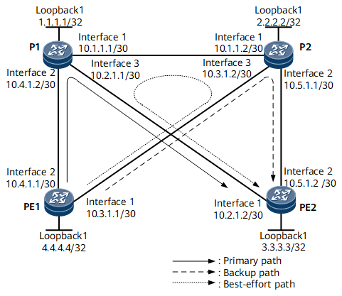
Figure 1 shows the dynamic BFD for CR-LSP networking. A TE tunnel between PE1 and PE2 is established. Hot standby and a best-effort LSP are configured for the TE tunnel. If the primary CR-LSP fails, traffic switches to the backup CR-LSP. After the primary CR-LSP recovers, traffic switches back to the primary CR-LSP after a 15-second delay. If both the primary and backup CR-LSPs fail, traffic switches to the best-effort path.
Dynamic BFD for CR-LSP is required to detect the primary and backup CR-LSPs. After the configuration, the following objects should be achieved:
If the primary CR-LSP fails, traffic switches to the backup CR-LSP at the millisecond level.
If the backup CR-LSP fails within 15 seconds after the primary CR-LSP recovers, traffic switches back to the primary CR-LSP.

Interfaces 1 through 3 in this example represent GE 0/1/0, GE 0/1/8, and GE 0/1/16, respectively.
Dynamic BFD configuration is simpler than static BFD configuration. In addition, dynamic BFD reduces the number of BFD sessions and uses less network resources because only a single BFD session can be created on a tunnel interface.
Configuration Roadmap
The configuration roadmap is as follows:
Configure CR-LSP hot standby according to Example for Configure a Hot-standby CR-LSP.
Enable BFD on the ingress of the tunnel. Configure MPLS TE BFD. Set the minimum intervals at which BFD packets are sent and received, and the local BFD detection multiplier.
Enable the capability of passively creating BFD sessions on the egress.
Data Preparation
To complete the configuration, you need the following data:
Minimum intervals at which BFD packets are sent and received on the ingress
Local BFD detection multiplier
For other data, see Example for Configure a Hot-standby CR-LSP.
Procedure
- Configure CR-LSP hot standby.
Configure the primary CR-LSP, hot-standby CR-LSP, and best-effort LSP based on Example for Configure a Hot-standby CR-LSP.
- Enable BFD on the ingress of the tunnel and configure MPLS TE BFD.
# Enable MPLS TE BFD on the tunnel interface of PE1. Set the minimum intervals at which BFD packets are sent and received to 100 milliseconds and the local BFD detection multiplier to 3.
<PE1> system-view
[~PE1] bfd
[*PE1-bfd] quit
[*PE1] interface Tunnel 10
[*PE1-Tunnel10] mpls te bfd enable
[*PE1-Tunenl10] mpls te bfd min-tx-interval 100 min-rx-interval 100 detect-multiplier 3
[*PE1-Tunenl10] commit
- Enable the capability of passively creating BFD sessions on the egress of the tunnel.
<PE2> system-view
[~PE2] bfd
[*PE2-bfd] mpls-passive
[*PE2-bfd] commit
[~PE2-bfd] quit
# Run the display bfd session mpls-te interface Tunnel command on PE1 and PE2. The status of BFD sessions is Up.
[~PE1] display bfd session mpls-te interface Tunnel 10 te-lsp
(w): State in WTR
(*): State is invalid
--------------------------------------------------------------------------------
Local Remote     PeerIpAddr      State     Type        InterfaceName
--------------------------------------------------------------------------------
16385 16385      3.3.3.3         Up        D_TE_LSP    Tunnel10
--------------------------------------------------------------------------------
    Total UP/DOWN Session Number : 1/0
- Verify the configuration.
Connect port 1 and port 2 on a tester to PE1 and PE2, respectively. Set correct label values. Inject traffic destined for port 2 into port 1. After the cable is removed from GE 0/1/8 on PE1 or P1, the fault is rectified within milliseconds.
After the cable is inserted into GE 0/1/8 and the cable is removed from GE 0/1/0 on PE1 after a 15-second delay, the fault is rectified within milliseconds.
Configuration Files
PE1 configuration file
#
sysname PE1
#
bfd
#
mpls lsr-id 4.4.4.4
#
mpls
 mpls te
 mpls rsvp-te
 mpls te cspf
#
explicit-path backup
 next hop 10.3.1.2
 next hop 10.5.1.2
 next hop 3.3.3.3
#
explicit-path main
 next hop 10.4.1.2
 next hop 10.2.1.2
 next hop 3.3.3.3
#
isis 1
 cost-style wide
 network-entity 10.0000.0000.0004.00
 traffic-eng level-1-2
#
interface GigabitEthernet0/1/0
 undo shutdown
 ip address 10.3.1.1 255.255.255.252
 isis enable 1
 mpls
 mpls te
 mpls rsvp-te
#
interface GigabitEthernet0/1/8
 undo shutdown
 ip address 10.4.1.1 255.255.255.252
 isis enable 1
 mpls
 mpls te
 mpls rsvp-te
#
interface LoopBack1
 ip address 4.4.4.4 255.255.255.255
 isis enable 1
#
interface Tunnel10
 ip address unnumbered interface LoopBack1
 tunnel-protocol mpls te
 destination 3.3.3.3
 mpls te record-route
 mpls te backup ordinary best-effort
 mpls te backup hot-standby
 mpls te tunnel-id 502
 mpls te path explicit-path main
 mpls te path explicit-path backup secondary
 mpls te bfd enable
 mpls te bfd min-tx-interval 100 min-rx-interval 100
#
return
P1 configuration file
#
sysname P1
#
mpls lsr-id 1.1.1.1
#
mpls
 mpls te
 mpls rsvp-te
#
isis 1
 cost-style wide
 network-entity 10.0000.0000.0001.00
 traffic-eng level-1-2
#
interface GigabitEthernet0/1/8
 undo shutdown
 ip address 10.4.1.2 255.255.255.252
 isis enable 1
 mpls
 mpls te
 mpls rsvp-te
#
interface GigabitEthernet0/1/0
 undo shutdown
 ip address 10.1.1.1 255.255.255.252
 isis enable 1
 mpls
 mpls te
 mpls rsvp-te
#
interface GigabitEthernet0/1/16
 undo shutdown
 ip address 10.2.1.1 255.255.255.252
 isis enable 1
 mpls
 mpls te
 mpls rsvp-te
#
interface LoopBack1
 ip address 1.1.1.1 255.255.255.255
 isis enable 1
#
return
P2 configuration file
#
sysname P2
#
mpls lsr-id 2.2.2.2
#
mpls
 mpls te
 mpls rsvp-te
#
isis 1
 cost-style wide
 network-entity 10.0000.0000.0002.00
 traffic-eng level-1-2
#
interface GigabitEthernet0/1/0
 undo shutdown
 ip address 10.1.1.2 255.255.255.252
 isis enable 1
 mpls
 mpls te
 mpls rsvp-te
#
interface GigabitEthernet0/1/8
 undo shutdown
 ip address 10.5.1.1 255.255.255.252
 isis enable 1
 mpls
 mpls te
 mpls rsvp-te
#
interface GigabitEthernet0/1/16
 undo shutdown
 ip address 10.3.1.2 255.255.255.252
 isis enable 1
 mpls
 mpls te
 mpls rsvp-te
#
interface LoopBack1
 ip address 2.2.2.2 255.255.255.255
 isis enable 1
#
return
PE2 configuration file
#
sysname PE2
#
bfd
 mpls-passive
#
mpls lsr-id 3.3.3.3
#
mpls
 mpls te
 mpls rsvp-te
#
isis 1
 cost-style wide
 network-entity 10.0000.0000.0003.00
 traffic-eng level-1-2
#
interface GigabitEthernet0/1/0
 undo shutdown
 ip address 10.2.1.2 255.255.255.252
 isis enable 1
 mpls
 mpls te
 mpls rsvp-te
#
interface GigabitEthernet0/1/8
 undo shutdown
 ip address 10.5.1.2 255.255.255.252
 isis enable 1
 mpls
 mpls te
 mpls rsvp-te
#
interface LoopBack1
 ip address 3.3.3.3 255.255.255.255
 isis enable 1
#
return