Example for Establishing a Static MPLS TE Tunnel
This section provides an example for configuring a static MPLS TE tunnel, which involves enabling MPLS TE, configuring the MPLS TE bandwidth, and setting up a static CR-LSP.
Networking Requirements
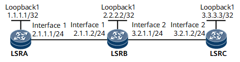
On the carrier network shown in Figure 1, some devices have low routing and processing performance. The carrier wants to use an MPLS TE tunnel to transmit services. To meet this requirement, two static TE tunnels between LSRA and LSRC can be established to transmit traffic in opposite directions. A static TE tunnel is manually established, without using a dynamic signaling protocol or IGP routes, which consumes a few device resources and has low requirement on device performance.
Configuration Roadmap
The configuration roadmap is as follows:
Assign an IP address to each interface on each LSR, and configure a loopback address as an MPLS LSR ID.
Configure the LSR ID and globally enable MPLS and MPLS TE on each node and interface.
Create a tunnel interface on the ingress and specify the IP address of the tunnel, tunnel protocol, destination address, tunnel ID, and the signaling protocol used to establish the tunnel.
- Configure a static CR-LSP associated with the tunnel and specify the following parameters on each type of node:
- Ingress: outgoing label and next-hop address
- Transit node: inbound interface name, next-hop address, and outgoing label
- Egress: incoming label and inbound interface name

The outgoing label of each node is the incoming label of the next node.
When running the static-cr-lsp ingress { tunnel-interface tunnel interface-number | tunnel-name } destination destination-address { nexthop next-hop-address | outgoing-interface interface-type interface-number } * out-label out-label command to configure the ingress of a CR-LSP, note that tunnel-name must be the same as the tunnel name created using the interface tunnel interface-number command. tunnel-name is a case-sensitive character string with no spaces. For example, the name of the tunnel created by using the interface Tunnel 20 command is Tunnel20. In this case, the parameter of the static CR-LSP on the ingress is Tunnel20. This restriction does not apply to transit nodes or egresses.
Data Preparation
To complete the configuration, you need the following data:
IP address of each interface
Tunnel interface names, tunnel interface IP addresses, destination addresses, tunnel IDs, and tunnel signaling protocol (CR-Static) on LSRA and LSRC
Next-hop address and outgoing label of the ingress on the static CR-LSP
Inbound interface name, next-hop address, and outgoing label of the transit node on the static CR-LSP
Inbound interface name of the egress on the static CR-LSP
Procedure
- Assign an IP address to each interface and configure a routing protocol.
Assign an IP address and a mask to each interface and configure the routing protocol using the information in Figure 1 to implement reachability between LSRs.
For configuration details, see Configuration Files in this section.
- Configure basic MPLS functions and enable MPLS TE.
# Configure LSRA.
[~LSRA] mpls lsr-id 1.1.1.1
[*LSRA] mpls
[*LSRA-mpls] mpls te
[*LSRA-mpls] quit
[*LSRA] interface gigabitethernet 0/1/0
[*LSRA-GigabitEthernet0/1/0] mpls
[*LSRA-GigabitEthernet0/1/0] mpls te
[*LSRA-GigabitEthernet0/1/0] commit
[~LSRA-GigabitEthernet0/1/0] quit
Repeat this step for LSRB and LSRC. For configuration details, see Configuration Files in this section.
- Configure an MPLS TE tunnel.
# Create the MPLS TE tunnel from LSRA to LSRC on LSRA.
[~LSRA] interface Tunnel 10
[*LSRA-Tunnel10] ip address unnumbered interface loopback 1
[*LSRA-Tunnel10] tunnel-protocol mpls te
[*LSRA-Tunnel10] destination 3.3.3.3
[*LSRA-Tunnel10] mpls te tunnel-id 100
[*LSRA-Tunnel10] mpls te signal-protocol cr-static
[*LSRA-Tunnel10] commit
[~LSRA-Tunnel10] quit
# Create the MPLS TE tunnel from LSRC to LSRA on LSRC.
[~LSRC] interface Tunnel 20
[*LSRC-Tunnel20] ip address unnumbered interface loopback 1
[*LSRC-Tunnel20] tunnel-protocol mpls te
[*LSRC-Tunnel20] destination 1.1.1.1
[*LSRC-Tunnel20] mpls te tunnel-id 200
[*LSRC-Tunnel20] mpls te signal-protocol cr-static
[*LSRC-Tunnel20] commit
[~LSRC-Tunnel20] quit
- Create a static CR-LSP from LSRA to LSRC.
# Configure LSRA as the ingress of the static CR-LSP.
[~LSRA] static-cr-lsp ingress tunnel-interface Tunnel 10 destination 3.3.3.3 nexthop 2.1.1.2 out-label 20
[*LSRA] commit
# Configure LSRB as the transit node of the static CR-LSP.
[~LSRB] static-cr-lsp transit Tunnel10 incoming-interface gigabitethernet 0/1/0 in-label 20 nexthop 3.2.1.2 out-label 30
[*LSRB] commit
# Configure LSRC as the egress of the static CR-LSP.
[~LSRC] static-cr-lsp egress Tunnel10 incoming-interface gigabitethernet 0/1/8 in-label 30
[*LSRC] commit
- Create a static CR-LSP from LSRC to LSRA.
# Configure LSRC as the ingress of the static CR-LSP.
[~LSRC] static-cr-lsp ingress tunnel-interface Tunnel 20 destination 1.1.1.1 nexthop 3.2.1.1 out-label 120
[*LSRC] commit
# Configure LSRB as the transit node of the static CR-LSP.
[~LSRB] static-cr-lsp transit Tunnel20 incoming-interface gigabitethernet 0/1/8 in-label 120 nexthop 2.1.1.1 out-label 130
[*LSRB] commit
# Configure LSRA as the egress of the static CR-LSP.
[~LSRA] static-cr-lsp egress Tunnel20 incoming-interface gigabitethernet 0/1/0 in-label 130
[*LSRA] commit
- Verify the configuration.
After completing the configuration, run the display interface tunnel command on LSRA. The command output shows that the status of the tunnel interface is Up.
Run the display mpls te tunnel command on each LSR to view the establishment status of the MPLS TE tunnel.
[~LSRA] display mpls te tunnel
* means the LSP is detour LSP
------------------------------------------------------------------------------
Ingress LsrId    Destination      LSPID   In/Out Label     R  Tunnel-name
------------------------------------------------------------------------------
1.1.1.1          3.3.3.3          1       --/20          I  Tunnel10
-                -                -       130/--         E  Tunnel20
------------------------------------------------------------------------------
R: Role, I: Ingress, T: Transit, E: Egress
[~LSRB] display mpls te tunnel
* means the LSP is detour LSP
------------------------------------------------------------------------------
Ingress LsrId    Destination      LSPID   In/Out Label     R  Tunnel-name
------------------------------------------------------------------------------
-                -                -       20/30            T  Tunnel10
-                -                -       120/130          T  Tunnel20
------------------------------------------------------------------------------
R: Role, I: Ingress, T: Transit, E: Egress
[~LSRC] display mpls te tunnel
* means the LSP is detour LSP
------------------------------------------------------------------------------
Ingress LsrId    Destination      LSPID   In/Out Label     R  Tunnel-name
------------------------------------------------------------------------------
-                -                -       30/--            E  Tunnel10
3.3.3.3          1.1.1.1          1       --/120           I  Tunnel20
------------------------------------------------------------------------------
R: Role, I: Ingress, T: Transit, E: Egress
Run the display mpls lsp or display mpls static-cr-lsp command on each LSR to view the establishment status of the static CR-LSP.
# Display the configuration on LSRA.
[~LSRA] display mpls static-cr-lsp
TOTAL          : 2     STATIC CRLSP(S)
UP             : 2     STATIC CRLSP(S)
DOWN           : 0     STATIC CRLSP(S)
Name            FEC              I/O Label  I/O If                    Status
Tunnel10    3.3.3.3/32        NULL/20    -/GE0/1/0                 Up
Tunnel20    -/-               130/NULL   GE0/1/0/-                 Up
# Display the configuration on LSRB.
[~LSRB] display mpls static-cr-lsp
TOTAL          : 2     STATIC CRLSP(S)
UP             : 2     STATIC CRLSP(S)
DOWN           : 0     STATIC CRLSP(S)
Name            FEC              I/O Label  I/O If                     Status
Tunnel10    -/-               20/30      GE0/1/0/GE0/1/8            Up
Tunnel20    -/-               120/130    GE0/1/8/GE0/1/0            Up
# Display the configuration on LSRC.
[~LSRC] display mpls static-cr-lsp
TOTAL          : 2     STATIC CRLSP(S)
UP             : 2     STATIC CRLSP(S)
DOWN           : 0     STATIC CRLSP(S)
Name            FEC                I/O Label  I/O If                    Status
Tunnel20    1.1.1.1/32          NULL/120   -/GE0/1/8                 Up
Tunnel10    -/-                 30/NULL    GE0/1/8/-                 Up
When the static CR-LSP is used to establish the MPLS TE tunnel, the packets on the transit node and the egress are forwarded directly based on the specified incoming and outgoing labels. Therefore, no FEC information is displayed on LSRB or LSRC.
Configuration Files
LSRA configuration file
#
sysname LSRA
#
mpls lsr-id 1.1.1.1
#
mpls
 mpls te
#
static-cr-lsp ingress tunnel-interface Tunnel10 destination 3.3.3.3 nexthop 2.1.1.2 out-label 20
#
static-cr-lsp egress Tunnel20 incoming-interface GigabitEthernet0/1/0 in-label 130
#
interface GigabitEthernet0/1/0
 undo shutdown
 ip address 2.1.1.1 255.255.255.0
 mpls
 mpls te
#
interface LoopBack1
 ip address 1.1.1.1 255.255.255.255
#
interface Tunnel10
 ip address unnumbered interface LoopBack1
 tunnel-protocol mpls te
 destination 3.3.3.3
 mpls te signal-protocol cr-static
 mpls te tunnel-id 100
#
return
LSRB configuration file
#
sysname LSRB
#
mpls lsr-id 2.2.2.2
#
mpls
 mpls te
#
static-cr-lsp transit Tunnel10 incoming-interface GigabitEthernet0/1/0 in-label 20 nexthop 3.2.1.2 out-label 30
#
static-cr-lsp transit Tunnel20 incoming-interface GigabitEthernet0/1/8 in-label 120 nexthop 2.1.1.1 out-label 130
#
interface GigabitEthernet0/1/8
 undo shutdown
 ip address 3.2.1.1 255.255.255.0
 mpls
 mpls te
#
interface GigabitEthernet0/1/0
 undo shutdown
 ip address 2.1.1.2 255.255.255.0
 mpls
 mpls te
#
interface LoopBack1
 ip address 2.2.2.2 255.255.255.255
#
return
LSRC configuration file
#
sysname LSRC
#
mpls lsr-id 3.3.3.3
#
mpls
 mpls te
#
static-cr-lsp ingress tunnel-interface Tunnel20 destination 1.1.1.1 nexthop 3.2.1.1 out-label 120
#
static-cr-lsp egress Tunnel10 incoming-interface GigabitEthernet0/1/8 in-label 30
#
interface GigabitEthernet0/1/8
 undo shutdown
 ip address 3.2.1.2 255.255.255.0
 mpls
 mpls te
#
interface GigabitEthernet0/1/0
 undo shutdown
#
interface LoopBack1
 ip address 3.3.3.3 255.255.255.255
#
interface Tunnel20
 ip address unnumbered interface LoopBack1
 tunnel-protocol mpls te
 destination 1.1.1.1
 mpls te signal-protocol cr-static
 mpls te tunnel-id 200
#
return