Example for Configuring a Static Bidirectional Co-routed CR-LSP
This section provides an example for configuring a static bidirectional co-routed CR-LSP, including how to enable MPLS TE, configure MPLS TE bandwidth attributes, and configure an MPLS TE tunnel.
Usage Scenario
Static bidirectional co-routed CR-LSPs are used to establish static bidirectional tunnel for services on an MPLS network.
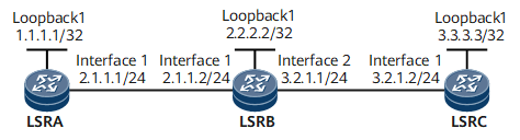
On a network shown in Figure 1, a static bidirectional co-routed CR-LSP originates from LSRA and terminates on LSRC. The links for the static bidirectional co-routed CR-LSP between LSRA and LSRC has 10 Mbit/s bandwidth.

Configuration Roadmap
The configuration roadmap is as follows:
Assign an IP address to each interface and configure a routing protocol.
Configure basic MPLS functions and enable MPLS TE.
Configure MPLS TE attributes for links.
Configure MPLS TE tunnels.
Configure the ingress, a transit node, and the egress for the static bidirectional co-routed CR-LSP.
Bind the tunnel interface configured on LSRC to the static bidirectional co-routed CR-LSP.
Data Preparation
To complete the configuration, you need the following data:
Tunnel interface's name and IP address, destination address, tunnel ID, and static CR-LSP signaling on LSRA and LSRC
Maximum reservable bandwidth and BC bandwidth of each link
Next-hop address and outgoing label on the ingress
Inbound interface, next-hop address, and outgoing label on the transit node
Inbound interface on the egress
Procedure
- Assign an IP address to each interface and configure a routing protocol.
# Assign an IP address and a mask to each interface and configure OSPF so that all LSRs are interconnected.
For configuration details, see Configuration Files in this section.
- Configure basic MPLS functions and enable MPLS TE.
# Configure LSRA.
[~LSRA] mpls lsr-id 1.1.1.1
[*LSRA] mpls
[*LSRA-mpls] mpls te
[*LSRA-mpls] quit
[*LSRA] interface gigabitethernet 0/1/0
[*LSRA-GigabitEthernet0/1/0] mpls
[*LSRA-GigabitEthernet0/1/0] mpls te
[*LSRA-GigabitEthernet0/1/0] commit
[~LSRA-GigabitEthernet0/1/0] quit
Repeat this step for LSRB and LSRC.
- Configure MPLS TE attributes for links.
# Configure the maximum reservable bandwidth and BC0 bandwidth for the link on the outbound interface of each LSR. The BC0 bandwidth of links must be greater than the tunnel bandwidth (10 Mbit/s).
# Configure LSRA.
[~LSRA] interface gigabitethernet 0/1/0
[~LSRA-GigabitEthernet0/1/0] mpls te bandwidth max-reservable-bandwidth 100000
[*LSRA-GigabitEthernet0/1/0] mpls te bandwidth bc0 100000
[*LSRA-GigabitEthernet0/1/0] commit
[~LSRA-GigabitEthernet0/1/0] quit
# Configure LSRB.
[~LSRB] interface gigabitethernet 0/1/0
[~LSRB-GigabitEthernet0/1/0] mpls te bandwidth max-reservable-bandwidth 100000
[*LSRB-GigabitEthernet0/1/0] mpls te bandwidth bc0 100000
[*LSRB-GigabitEthernet0/1/0] quit
[*LSRB] interface gigabitethernet 0/1/1
[*LSRB-GigabitEthernet0/1/1] mpls te bandwidth max-reservable-bandwidth 100000
[*LSRB-GigabitEthernet0/1/1] mpls te bandwidth bc0 100000
[*LSRB-GigabitEthernet0/1/1] commit
[~LSRB-GigabitEthernet0/1/1] quit
# Configure LSRC.
[~LSRC] interface gigabitethernet 0/1/0
[*LSRC-GigabitEthernet0/1/0] mpls te bandwidth max-reservable-bandwidth 100000
[*LSRC-GigabitEthernet0/1/0] mpls te bandwidth bc0 100000
[*LSRC-GigabitEthernet0/1/0] commit
[~LSRC-GigabitEthernet0/1/0] quit
- Configure MPLS TE tunnel interfaces.
# Create an MPLS TE tunnel from LSRA to LSRC.
[~LSRA] interface Tunnel 10
[*LSRA-Tunnel10] ip address unnumbered interface loopback 1
[*LSRA-Tunnel10] tunnel-protocol mpls te
[*LSRA-Tunnel10] destination 3.3.3.3
[*LSRA-Tunnel10] mpls te tunnel-id 100
[*LSRA-Tunnel10] mpls te signal-protocol cr-static
[*LSRA-Tunnel10] mpls te bidirectional
[*LSRA-Tunnel10] commit
[~LSRA-Tunnel10] quit
# Create an MPLS TE tunnel from LSRC to LSRA.
[~LSRC] interface Tunnel 20
[*LSRC-Tunnel20] ip address unnumbered interface loopback 1
[*LSRC-Tunnel20] tunnel-protocol mpls te
[*LSRC-Tunnel20] destination 1.1.1.1
[*LSRC-Tunnel20] mpls te tunnel-id 200
[*LSRC-Tunnel20] mpls te signal-protocol cr-static
[*LSRC-Tunnel20] commit
[~LSRC-Tunnel20] quit
- Configure the ingress, a transit node, and the egress for the static bidirectional co-routed CR-LSP.# Configure LSRA as the ingress.
[~LSRA] bidirectional static-cr-lsp ingress Tunnel 10
[*LSRA-bi-static-ingress-Tunnel10] forward nexthop 2.1.1.2 out-label 20 bandwidth ct0 10000 pir 10000
[*LSRA-bi-static-ingress-Tunnel10] backward in-label 20
[*LSRA-bi-static-ingress-Tunnel10] commit
[~LSRA-bi-static-ingress-Tunnel10] quit
# Configure LSRB as a transit node.[~LSRB]bidirectional static-cr-lsp transit lsp1 [*LSRB-bi-static-transit-lsp1] forward in-label 20 nexthop 3.2.1.2 out-label 40 bandwidth ct0 10000 pir 10000 [*LSRB-bi-static-transit-lsp1] backward in-label 16 nexthop 2.1.1.1 out-label 20 bandwidth ct0 10000 pir 10000 [*LSRB-bi-static-transit-lsp1] commit [~LSRB-bi-static-transit-lsp1] quit
# Configure LSRC as the egress.[~LSRC] bidirectional static-cr-lsp egress Tunnel20 [*LSRC-bi-static-egress-Tunnel20] forward in-label 40 lsrid 1.1.1.1 tunnel-id 100 [*LSRC-bi-static-egress-Tunnel20] backward nexthop 3.2.1.1 out-label 16 bandwidth ct0 10000 pir 10000 [*LSRC-bi-static-egress-Tunnel20] commit [~LSRC-bi-static-egress-Tunnel20] quit
- Bind the static bidirectional co-routed CR-LSP to the tunnel interface on LSRC.
[~LSRC] interface Tunnel20
[~LSRC-Tunnel20] mpls te passive-tunnel
[*LSRC-Tunnel20] mpls te binding bidirectional static-cr-lsp egress Tunnel20
[*LSRC-Tunnel20] commit
[~LSRC-Tunnel20] quit
- Verify the configuration.
After completing the configuration, run the display interface tunnel command on LSRA. The command output shows that the tunnel interface is Up.
Run the display mpls te tunnel command on each LSR. The command output shows that MPLS TE tunnels have been established.
# Check the configuration on LSRA.
[~LSRA] display mpls te tunnel
* means the LSP is detour LSP
-------------------------------------------------------------------------------
Ingress LsrId   Destination     LSPID In/OutLabel     R Tunnel-name
-------------------------------------------------------------------------------
1.1.1.1         3.3.3.3         0     --/20           I Tunnel10
                                      20/--
-------------------------------------------------------------------------------
R: Role, I: Ingress, T: Transit, E: Egress
# Check the configuration on LSRB.
[~LSRB] display mpls te tunnel
* means the LSP is detour LSP
-------------------------------------------------------------------------------
Ingress LsrId   Destination     LSPID In/OutLabel     R Tunnel-name
-------------------------------------------------------------------------------
-               -               -     20/40           T lsp1
                                      16/20
-------------------------------------------------------------------------------
R: Role, I: Ingress, T: Transit, E: Egress
# Check the configuration results on LSRC.
[~LSRC] display mpls te tunnel
* means the LSP is detour LSP
-------------------------------------------------------------------------------
Ingress LsrId   Destination     LSPID In/OutLabel     R Tunnel-name
-------------------------------------------------------------------------------
1.1.1.1         3.3.3.3         -     40/--           E Tunnel20
                                      --/16
-------------------------------------------------------------------------------
R: Role, I: Ingress, T: Transit, E: Egress
Run the display mpls te bidirectional static-cr-lsp command on each LSR to view information about the static bidirectional co-routed CR-LSP.
# Check the configuration on LSRA.
[~LSRA] display mpls te bidirectional static-cr-lsp
TOTAL          : 1     STATIC CRLSP(S)
UP             : 1     STATIC CRLSP(S)
DOWN           : 0     STATIC CRLSP(S)
Name                FEC                I/O Label    I/O If                Status
Tunnel10         3.3.3.3/32         NULL/20      -/GE0/1/0
                                       20/NULL      GE0/1/0/-             Up
# Check the configuration on LSRB.
[~LSRB] display mpls te bidirectional static-cr-lsp
TOTAL          : 1     STATIC CRLSP(S)
UP             : 1     STATIC CRLSP(S)
DOWN           : 0     STATIC CRLSP(S)
Name                FEC                I/O Label    I/O If                Status
lsp1                -/32               20/40        GE0/1/0/GE0/1/8
                                       16/20        GE0/1/8/GE0/1/0       Up
# Check the configuration on LSRC.
[~LSRC] display mpls te bidirectional static-cr-lsp
TOTAL          : 1     STATIC CRLSP(S)
UP             : 1     STATIC CRLSP(S)
DOWN           : 0     STATIC CRLSP(S)
Name                FEC                I/O Label    I/O If                Status
Tunnel20         1.1.1.1/32         40/NULL      GE0/1/0/-
                                       NULL/16      -/GE0/1/0             Up
After completing the configuration, run the ping command on LSRA. The static bidirectional co-routed CR-LSP is reachable.[~LSRA] ping lsp -a 1.1.1.1 te Tunnel 10 LSP PING FEC: TE TUNNEL IPV4 SESSION QUERY Tunnel10 : 100 data bytes, press CTRL_C to break Reply from 3.3.3.3: bytes=100 Sequence=1 time = 56 ms Reply from 3.3.3.3: bytes=100 Sequence=2 time = 53 ms Reply from 3.3.3.3: bytes=100 Sequence=3 time = 3 ms Reply from 3.3.3.3: bytes=100 Sequence=4 time = 60 ms Reply from 3.3.3.3: bytes=100 Sequence=5 time = 5 ms --- FEC: RSVP IPV4 SESSION QUERY Tunnel10 ping statistics --- 5 packet(s) transmitted 5 packet(s) received 0.00% packet loss round-trip min/avg/max = 3/35/60 ms
Configuration Files
LSRA configuration file
#
sysname LSRA
#
mpls lsr-id 1.1.1.1
#
mpls
 mpls te
#
bidirectional static-cr-lsp ingress Tunnel10
 forward nexthop 2.1.1.2 out-label 20 bandwidth ct0 10000 pir 10000
 backward in-label 20

#
interface GigabitEthernet0/1/0
 undo shutdown
 ip address 2.1.1.1 255.255.255.0
 mpls
 mpls te
 mpls te bandwidth max-reservable-bandwidth 100000
 mpls te bandwidth bc0 100000
#
interface LoopBack1
 ip address 1.1.1.1 255.255.255.255
#
interface Tunnel10
 ip address unnumbered interface LoopBack1
 tunnel-protocol mpls te
 destination 3.3.3.3
 mpls te signal-protocol cr-static
 mpls te tunnel-id 100
 mpls te bidirectional
#
ip route-static 2.2.2.2 255.255.255.255 2.1.1.2
ip route-static 3.3.3.3 255.255.255.255 2.1.1.2
#
return
LSRB configuration file
#
sysname LSRB
#
mpls lsr-id 2.2.2.2
#
mpls
 mpls te
#
bidirectional static-cr-lsp transit lsp1
 forward in-label 20 nexthop 3.2.1.2 out-label 40 bandwidth ct0 10000 pir 10000
 backward in-label 16 nexthop 2.1.1.1 out-label 20 bandwidth ct0 10000 pir 10000
#
interface GigabitEthernet0/1/0
 undo shutdown
 ip address 2.1.1.2 255.255.255.0
 mpls
 mpls te
 mpls te bandwidth max-reservable-bandwidth 100000
 mpls te bandwidth bc0 100000
#
interface GigabitEthernet0/1/1
 undo shutdown
 ip address 3.2.1.1 255.255.255.0
 mpls
 mpls te
 mpls te bandwidth max-reservable-bandwidth 100000
 mpls te bandwidth bc0 100000
#
interface LoopBack1
 ip address 2.2.2.2 255.255.255.255
#
ip route-static 1.1.1.1 255.255.255.255 2.1.1.1
ip route-static 3.3.3.3 255.255.255.255 3.2.1.2
#
return
LSRC configuration file
#
sysname LSRC
#
mpls lsr-id 3.3.3.3
#
mpls
 mpls te
#
bidirectional static-cr-lsp egress Tunnel20
 forward in-label 40 lsrid 1.1.1.1 tunnel-id 100
 backward nexthop 3.2.1.1 out-label 16 bandwidth ct0 10000 pir 10000
#
interface GigabitEthernet0/1/0
 undo shutdown
 ip address 3.2.1.2 255.255.255.0
 mpls
 mpls te
 mpls te bandwidth max-reservable-bandwidth 100000
 mpls te bandwidth bc0 100000
#
interface LoopBack1
 ip address 3.3.3.3 255.255.255.255
#
interface Tunnel20
 ip address unnumbered interface LoopBack1
 tunnel-protocol mpls te
 destination 1.1.1.1
 mpls te signal-protocol cr-static
 mpls te tunnel-id 200
 mpls te passive-tunnel
 mpls te binding bidirectional static-cr-lsp egress Tunnel20
#
ip route-static 1.1.1.1 255.255.255.255 3.2.1.1
ip route-static 2.2.2.2 255.255.255.255 3.2.1.1
#
return