Example for Configuring an Associated Bidirectional Static CR-LSP
This section provides an example for configuring an associated bidirectional static CR-LSP.
Networking Requirements
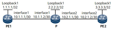
In Figure 1, a forward static CR-LSP is established along the path PE1 -> PE2, and a reverse static CR-LSP is established along the path PE2 -> PE1. To allow a traffic switchover to be performed on both CR-LSPs, bind the two static CR-LSPs to each other to form an associated bidirectional static CR-LSP.
Configuration Roadmap
The configuration roadmap is as follows:
Assign an IP address to every interface and configure a loopback interface address as an LSR ID on every node.
Configure a forward static CR-LSP and a reverse static CR-LSP.
Bind the forward and reverse static CR-LSPs to each other.
Data Preparation

In this example, a forward static CR-LSP is established along the path PE1 -> PE2, and a reverse static CR-LSP is established along the path PE2 -> PE1.
Device Name |
Parameter |
Value |
|---|---|---|
PE1 |
Number of a tunnel interface on the forward CR-LSP |
Tunnel10 |
Tunnel ID of the forward CR-LSP |
100 |
|
Outgoing label of the forward CR-LSP |
20 |
|
Name of the reverse CR-LSP |
Tunnel20 |
|
Incoming label of the reverse CR-LSP |
130 |
|
P |
Name of the forward CR-LSP |
Tunnel10 |
Incoming label of the forward CR-LSP |
20 |
|
Outgoing label of the forward CR-LSP |
30 |
|
Name of the reverse CR-LSP |
Tunnel20 |
|
Incoming label of the reverse CR-LSP |
120 |
|
Outgoing label of the reverse CR-LSP |
130 |
|
PE2 |
Number of a tunnel interface on the reverse CR-LSP |
Tunnel20 |
Tunnel ID of the reverse CR-LSP |
200 |
|
Outgoing label of the reverse CR-LSP |
120 |
|
Name of the forward CR-LSP |
Tunnel10 |
|
Incoming label of the forward CR-LSP |
30 |
Procedure
- Assign an IP address and a mask to each interface.
Assign IP addresses and masks to interfaces. For configuration details, see Configuration Files in this section.
- Configure a forward static CR-LSP and a reverse static CR-LSP.
For configuration details, see Configuration Files in this section.
- Bind the forward and reverse static CR-LSPs to each other.
# Configure PE1.
[~PE1] interface Tunnel 10
[~PE1-Tunnel10] mpls te reverse-lsp protocol static lsp-name Tunnel20
[*PE1-Tunnel10] commit
# Configure PE2.
[~PE2] interface Tunnel 20
[~PE2-Tunnel20] mpls te reverse-lsp protocol static lsp-name Tunnel10
[*PE2-Tunnel20] commit
- Verify the configuration.
After completing the preceding configurations, run the display mpls te reverse-lsp verbose command on PE1 and PE2 to view reserve static CR-LSP information. The following example uses the command output on PE1.
[~PE1] display mpls te reverse-lsp verbose
-------------------------------------------------------------------------------
                 LSP Information: STATIC LSP
-------------------------------------------------------------------------------
  Obverse Tunnel           :  Tunnel10      //Tunnel interface on the forward CR-LSP
  Reverse LSP Name         :  Tunnel20      //Name of the reverse CR-LSP
  Reverse LSP State        :  Up               //Status of the reverse CR-LSP
  Incoming Label           :  130
  Incoming Interface       :  GE0/1/0
Configuration Files
PE1 configuration file
#
sysname PE1
#
mpls lsr-id 1.1.1.1
#
mpls
 mpls te
#
interface GigabitEthernet0/1/0
 undo shutdown
 ip address 10.1.1.1 255.255.255.252
 mpls
 mpls te
#
interface LoopBack1
 ip address 1.1.1.1 255.255.255.255
#
interface Tunnel10
 ip address unnumbered interface LoopBack1
 tunnel-protocol mpls te
 destination 3.3.3.3
 mpls te signal-protocol cr-static
 mpls te reverse-lsp protocol static lsp-name Tunnel20
 mpls te tunnel-id 100
#
static-cr-lsp ingress tunnel-interface Tunnel10 destination 3.3.3.3 nexthop 10.1.1.2 out-label 20
#
static-cr-lsp egress Tunnel20 incoming-interface GigabitEthernet0/1/0 in-label 130
#
return
P configuration file
#
sysname P
#
mpls lsr-id 2.2.2.2
#
mpls
 mpls te
#
interface GigabitEthernet0/1/0
 undo shutdown
 ip address 10.1.1.2 255.255.255.252
 mpls
 mpls te
#
interface GigabitEthernet0/1/8
 undo shutdown
 ip address 10.2.1.1 255.255.255.252
 mpls
 mpls te
#
interface LoopBack1
 ip address 2.2.2.2 255.255.255.255
#
static-cr-lsp transit Tunnel10 incoming-interface GigabitEthernet0/1/0 in-label 20 nexthop 10.2.1.2 out-label 30
#
static-cr-lsp transit Tunnel20 incoming-interface GigabitEthernet0/1/8 in-label 120 nexthop 10.1.1.1 out-label 130
#
return
PE2 configuration file
#
sysname PE2
#
mpls lsr-id 3.3.3.3
#
mpls
 mpls te
#
interface GigabitEthernet0/1/8
 undo shutdown
 ip address 10.2.1.2 255.255.255.252
 mpls
 mpls te
#
interface LoopBack1
 ip address 3.3.3.3 255.255.255.255
#
interface Tunnel20
 ip address unnumbered interface LoopBack1
 tunnel-protocol mpls te
 destination 1.1.1.1
 mpls te signal-protocol cr-static
 mpls te reverse-lsp protocol static lsp-name Tunnel10
 mpls te tunnel-id 200
#
static-cr-lsp ingress tunnel-interface Tunnel20 destination 1.1.1.1 nexthop 10.2.1.1 out-label 120
#
static-cr-lsp egress Tunnel10 incoming-interface GigabitEthernet0/1/8 in-label 30
#
return