Example for Configuring an RSVP-TE over GRE Tunnel
Networking Requirements
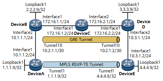
On the network shown in Figure 1, OSPF runs on DeviceB, DeviceC, and DeviceD, and a GRE tunnel is established between DeviceB and DeviceD. A TE tunnel with 10 Mbit/s bandwidth is required between DeviceA and DeviceE. The maximum reservable link bandwidth of the tunnel is 10 Mbit/s, as is the BC0 bandwidth.

Configuration Precautions
In this example, an RSVP-TE over GRE tunnel is configured, and the GRE tunnel interfaces cannot borrow the IP addresses of other interfaces. During configuration, you can enable an IGP on GRE tunnel interfaces and configure MPLS link attributes.
Configuration Roadmap
The configuration roadmap is as follows:
Assign an IP address to each interface, including the loopback interface whose address is to be used as an LSR ID on each involved node.
- Configure OSPF on DeviceB, DeviceC, and DeviceD, and establish a GRE tunnel between DeviceB and DeviceD.
Enable IS-IS globally, configure a network entity title (NET), specify the cost type, and enable IS-IS TE. Enable IS-IS on each interface (including loopback interfaces and GRE tunnel interfaces).
Configure MPLS LSR-IDs, and enable MPLS, MPLS TE, MPLS RSVP-TE, and MPLS CSPF globally.
Enable MPLS, MPLS TE, and MPLS RSVP-TE on each interface.
Configure the maximum reservable link bandwidth and BC bandwidth on the outbound interfaces of each involved tunnel.
Create a tunnel interface on the ingress and configure an IP address, tunnel protocol, destination IP address, and tunnel bandwidth.
Data Preparation
To complete the configuration, you need the following data:
IS-IS area ID, originating system ID, and IS-IS level of each node
Maximum bandwidth and maximum reservable bandwidth for each link along the tunnel
Tunnel interface number, IP address, destination IP address, tunnel ID, and tunnel bandwidth
Procedure
- Configure an IP address for each interface.
Assign an IP address and a mask to each interface according to Figure 1. The configuration details are not provided.
- Establish a GRE tunnel between DeviceB and DeviceD.
# Configure DeviceB.
[~DeviceB] ospf 1
[*DeviceB-ospf-1] area 0.0.0.0
[*DeviceB-ospf-1-area-0.0.0.0] network 2.2.2.9 0.0.0.0
[*DeviceB-ospf-1-area-0.0.0.0] network 172.16.1.0 0.0.0.255
[*DeviceB-ospf-1-area-0.0.0.0] quit
[*DeviceB-ospf-1] quit
[*DeviceB] interface LoopBack1
[*DeviceB-LoopBack1] binding tunnel gre
[*DeviceB-LoopBack1] quit
[*DeviceB] interface Tunnel10
[*DeviceB-Tunnel10] ip address 10.2.1.1 255.255.255.252
[*DeviceB-Tunnel10] tunnel-protocol gre
[*DeviceB-Tunnel10] source 2.2.2.9
[*DeviceB-Tunnel10] destination 3.3.3.9
[*DeviceB-Tunnel10] quit
[*DeviceB] commit
# Configure DeviceC.
[~DeviceC] ospf 1
[*DeviceC-ospf-1] area 0.0.0.0
[*DeviceC-ospf-1-area-0.0.0.0] network 172.16.1.0 0.0.0.255
[*DeviceC-ospf-1-area-0.0.0.0] network 172.16.2.0 0.0.0.255
[*DeviceC-ospf-1-area-0.0.0.0] quit
[*DeviceC-ospf-1] quit
[*DeviceC] commit
# Configure DeviceD.
[~DeviceD] ospf 1
[*DeviceD-ospf-1] area 0.0.0.0
[*DeviceD-ospf-1-area-0.0.0.0] network 3.3.3.9 0.0.0.0
[*DeviceD-ospf-1-area-0.0.0.0] network 172.16.2.0 0.0.0.255
[*DeviceD-ospf-1-area-0.0.0.0] quit
[*DeviceD-ospf-1] quit
[*DeviceD] interface LoopBack1
[*DeviceD-LoopBack1] binding tunnel gre
[*DeviceD-LoopBack1] quit
[*DeviceD] interface Tunnel10
[*DeviceD-Tunnel10] ip address 10.2.1.2 255.255.255.252
[*DeviceD-Tunnel10] tunnel-protocol gre
[*DeviceD-Tunnel10] source 3.3.3.9
[*DeviceD-Tunnel10] destination 2.2.2.9
[*DeviceD-Tunnel10] quit
[*DeviceD] commit
After completing the configuration, run the display interface tunnel command. The command output shows that the tunnel interface is in the Up state. The following example uses the command output on DeviceB.
[~DeviceB] display interface tunnel 10
Tunnel10 current state : UP (ifindex: 30)
Line protocol current state : UP
Last line protocol up time : 2021-05-12 03:38:08
Description:
Route Port,The Maximum Transmit Unit is 1500
Internet Address is 10.2.1.1/30
Encapsulation is TUNNEL, loopback not set
Tunnel source 2.2.2.9 (LoopBack1), destination 3.3.3.9
Tunnel protocol/transport GRE/IP, key disabled
keepalive disabled
Checksumming of packets disabled
Current system time: 2021-05-12 06:29:08
    300 seconds input rate 0 bits/sec, 0 packets/sec
    300 seconds output rate 0 bits/sec, 0 packets/sec
    0 seconds input rate 0 bits/sec, 0 packets/sec
    0 seconds output rate 0 bits/sec, 0 packets/sec
    1834 packets input,  212950 bytes
    0 input error
    1837 packets output,  218381 bytes
    0 output error
    Input:
      Unicast: 1834 packets, Multicast: 0 packets
    Output:
      Unicast: 1837 packets, Multicast: 0 packets
    Input bandwidth utilization  :    0%
    Output bandwidth utilization :    0%
Run the display tunnel-info all command to check information about all tunnels. The following example uses the command output on DeviceB.
[~DeviceB] display tunnel-info all Tunnel ID Type Destination Status ---------------------------------------------------------------------------------------- 0x00000000050000001e gre 3.3.3.9 UP - Configure IS-IS to advertise routes.
Note that IS-IS must also be enabled on the GRE tunnel interfaces.
# Configure DeviceA.
[~DeviceA] isis 1
[*DeviceA-isis-1] network-entity 00.0005.0000.0000.0001.00
[*DeviceA-isis-1] is-level level-2
[*DeviceA-isis-1] quit
[*DeviceA] interface gigabitethernet 0/1/0
[*DeviceA-GigabitEthernet0/1/0] isis enable 1
[*DeviceA-GigabitEthernet0/1/0] quit
[*DeviceA] interface loopback 1
[*DeviceA-LoopBack1] isis enable 1
[*DeviceA-LoopBack1] commit
[~DeviceA-LoopBack1] quit
# Configure DeviceB.
[~DeviceB] isis 1
[*DeviceB-isis-1] network-entity 00.0005.0000.0000.0002.00
[*DeviceB-isis-1] is-level level-2
[*DeviceB-isis-1] quit
[*DeviceB] interface Tunnel10
[*DeviceB-Tunnel10] isis enable 1
[*DeviceB-Tunnel10] quit
[*DeviceB] interface gigabitethernet 0/1/8
[*DeviceB-GigabitEthernet0/1/8] isis enable 1
[*DeviceB-GigabitEthernet0/1/8] quit
[*DeviceB] interface loopback 1
[*DeviceB-LoopBack1] isis enable 1
[*DeviceB-LoopBack1] commit
[~DeviceB-LoopBack1] quit
# Configure DeviceD.
[~DeviceD] isis 1
[*DeviceD-isis-1] network-entity 00.0005.0000.0000.0003.00
[*DeviceD-isis-1] is-level level-2
[*DeviceD-isis-1] quit
[*DeviceD] interface Tunnel10
[*DeviceD-Tunnel10] isis enable 1
[*DeviceD-Tunnel10] quit
[*DeviceD] interface gigabitethernet 0/1/8
[*DeviceD-GigabitEthernet0/1/8] isis enable 1
[*DeviceD-GigabitEthernet0/1/8] quit
[*DeviceD] interface loopback 1
[*DeviceD-LoopBack1] isis enable 1
[*DeviceD-LoopBack1] commit
[~DeviceD-LoopBack1] quit
# Configure DeviceE.
[~DeviceE] isis 1
[*DeviceE-isis-1] network-entity 00.0005.0000.0000.0004.00
[*DeviceE-isis-1] is-level level-2
[*DeviceE-isis-1] quit
[*DeviceE] interface gigabitethernet 0/1/0
[*DeviceE-GigabitEthernet0/1/0] isis enable 1
[*DeviceE-GigabitEthernet0/1/0] quit
[*DeviceE] interface loopback 1
[*DeviceE-LoopBack1] isis enable 1
[*DeviceE-LoopBack1] commit
[~DeviceE-LoopBack1] quit
After completing the configuration, run the display ip routing-table command on each node. The command output shows that all the nodes have learned routes from each other. The following example uses the command output on DeviceA.
[~DeviceA] display ip routing-table
Route Flags: R - relay, D - download to fib, T - to vpn-instance, B - black hole route
------------------------------------------------------------------------------
Routing Table : _public_
         Destinations : 13       Routes : 13

Destination/Mask    Proto   Pre  Cost        Flags NextHop         Interface

        1.1.1.9/32  Direct  0    0             D   127.0.0.1       LoopBack1
        2.2.2.9/32  ISIS-L2 15   10            D   10.1.1.1        GigabitEthernet0/1/0
        3.3.3.9/32  ISIS-L2 15   20            D   10.1.1.1        GigabitEthernet0/1/0
        4.4.4.9/32  ISIS-L2 15   30            D   10.1.1.1        GigabitEthernet0/1/0
       10.1.1.0/24  Direct  0    0             D   10.1.1.2        GigabitEthernet0/1/0
       10.1.1.2/32  Direct  0    0             D   127.0.0.1       GigabitEthernet0/1/0
     10.1.1.255/32  Direct  0    0             D   127.0.0.1       GigabitEthernet0/1/0
       10.2.1.0/30  ISIS-L2 15   20            D   10.1.1.1        GigabitEthernet0/1/0
       10.3.1.0/24  ISIS-L2 15   30            D   10.1.1.1        GigabitEthernet0/1/0
      127.0.0.0/8   Direct  0    0             D   127.0.0.1       InLoopBack0
      127.0.0.1/32  Direct  0    0             D   127.0.0.1       InLoopBack0
127.255.255.255/32  Direct  0    0             D   127.0.0.1       InLoopBack0
255.255.255.255/32  Direct  0    0             D   127.0.0.1       InLoopBack0
- Configure basic MPLS functions, and enable MPLS TE, RSVP-TE, and CSPF.
Enable MPLS, MPLS TE, and RSVP-TE globally on each node and on all interfaces along the tunnel, and enable CSPF on the ingress. Note that you also need to perform related configurations on the GRE tunnel interfaces.
# Configure DeviceA.
[~DeviceA] mpls lsr-id 1.1.1.9
[*DeviceA] mpls
[*DeviceA-mpls] mpls te
[*DeviceA-mpls] mpls rsvp-te
[*DeviceA-mpls] mpls te cspf
[*DeviceA-mpls] quit
[*DeviceA] interface gigabitethernet 0/1/0
[*DeviceA-GigabitEthernet0/1/0] mpls
[*DeviceA-GigabitEthernet0/1/0] mpls te
[*DeviceA-GigabitEthernet0/1/0] mpls rsvp-te
[*DeviceA-GigabitEthernet0/1/0] commit
[~DeviceA-GigabitEthernet0/1/0] quit
# Configure DeviceB.
[~DeviceB] mpls lsr-id 2.2.2.9
[*DeviceB] mpls
[*DeviceB-mpls] mpls te
[*DeviceB-mpls] mpls rsvp-te
[*DeviceB-mpls] quit
[*DeviceB] interface Tunnel10
[*DeviceB-Tunnel10] mpls
[*DeviceB-Tunnel10] mpls te
[*DeviceB-Tunnel10] mpls rsvp-te
[*DeviceB-Tunnel10] quit
[*DeviceB] interface gigabitethernet 0/1/8
[*DeviceB-GigabitEthernet0/1/8] mpls
[*DeviceB-GigabitEthernet0/1/8] mpls te
[*DeviceB-GigabitEthernet0/1/8] mpls rsvp-te
[*DeviceB-GigabitEthernet0/1/8] commit
[~DeviceB-GigabitEthernet0/1/8] quit
# Configure DeviceD.
[~DeviceD] mpls lsr-id 3.3.3.9
[*DeviceD] mpls
[*DeviceD-mpls] mpls te
[*DeviceD-mpls] mpls rsvp-te
[*DeviceD-mpls] quit
[*DeviceD] interface Tunnel10
[*DeviceD-Tunnel10] mpls
[*DeviceD-Tunnel10] mpls te
[*DeviceD-Tunnel10] mpls rsvp-te
[*DeviceD-Tunnel10] quit
[*DeviceD] interface gigabitethernet 0/1/8
[*DeviceD-GigabitEthernet0/1/8] mpls
[*DeviceD-GigabitEthernet0/1/8] mpls te
[*DeviceD-GigabitEthernet0/1/8] mpls rsvp-te
[*DeviceD-GigabitEthernet0/1/8] commit
[~DeviceD-GigabitEthernet0/1/8] quit
# Configure DeviceE.
[~DeviceE] mpls lsr-id 4.4.4.9
[*DeviceE] mpls
[*DeviceE-mpls] mpls te
[*DeviceE-mpls] mpls rsvp-te
[*DeviceE-mpls] mpls te cspf
[*DeviceE-mpls] quit
[*DeviceE] interface gigabitethernet 0/1/0
[*DeviceE-GigabitEthernet0/1/0] mpls
[*DeviceE-GigabitEthernet0/1/0] mpls te
[*DeviceE-GigabitEthernet0/1/0] mpls rsvp-te
[*DeviceE-GigabitEthernet0/1/0] commit
[~DeviceE-GigabitEthernet0/1/0] quit
- Configure IS-IS TE.
# Configure DeviceA.
[~DeviceA] isis 1
[~DeviceA-isis-1] cost-style wide
[*DeviceA-isis-1] traffic-eng level-2
[*DeviceA-isis-1] commit
[~DeviceA-isis-1] quit
# Configure DeviceB.
[~DeviceB] isis 1
[~DeviceB-isis-1] cost-style wide
[*DeviceB-isis-1] traffic-eng level-2
[*DeviceB-isis-1] commit
[~DeviceB-isis-1] quit
# Configure DeviceD.
[~DeviceD] isis 1
[~DeviceD-isis-1] cost-style wide
[*DeviceD-isis-1] traffic-eng level-2
[*DeviceD-isis-1] commit
[~DeviceD-isis-1] quit
# Configure DeviceE.
[~DeviceE] isis 1
[~DeviceE-isis-1] cost-style wide
[*DeviceE-isis-1] traffic-eng level-2
[*DeviceE-isis-1] commit
[~DeviceE-isis-1] quit
- Configure MPLS TE bandwidth attributes for links.
Configure the maximum reservable link bandwidth and BC0 bandwidth on the outbound interfaces of each involved tunnel. Note that you also need to perform related configurations on the GRE tunnel interfaces.
# Configure DeviceA.
[~DeviceA] interface gigabitethernet 0/1/0
[~DeviceA-GigabitEthernet0/1/0] mpls te bandwidth max-reservable-bandwidth 10000
[*DeviceA-GigabitEthernet0/1/0] mpls te bandwidth bc0 10000
[*DeviceA-GigabitEthernet0/1/0] commit
[~DeviceA-GigabitEthernet0/1/0] quit
# Configure DeviceB.
[~DeviceB] interface Tunnel10
[~DeviceB-Tunnel10] bandwidth 100000
[*DeviceB-Tunnel10] mpls te bandwidth max-reservable-bandwidth 10000
[*DeviceB-Tunnel10] mpls te bandwidth bc0 10000
[*DeviceB-Tunnel10] quit
[*DeviceB] interface gigabitethernet 0/1/8
[*DeviceB-GigabitEthernet0/1/8] mpls te bandwidth max-reservable-bandwidth 10000
[*DeviceB-GigabitEthernet0/1/8] mpls te bandwidth bc0 10000
[*DeviceB-GigabitEthernet0/1/8] commit
[~DeviceB-GigabitEthernet0/1/8] quit
# Configure DeviceD.
[~DeviceD] interface Tunnel10
[~DeviceB-Tunnel10] bandwidth 100000
[*DeviceD-Tunnel10] mpls te bandwidth max-reservable-bandwidth 10000
[*DeviceD-Tunnel10] mpls te bandwidth bc0 10000
[*DeviceD-Tunnel10] quit
[~DeviceD] interface gigabitethernet 0/1/8
[~DeviceD-GigabitEthernet0/1/8] mpls te bandwidth max-reservable-bandwidth 10000
[*DeviceD-GigabitEthernet0/1/8] mpls te bandwidth bc0 10000
[*DeviceD-GigabitEthernet0/1/8] commit
[~DeviceD-GigabitEthernet0/1/8] quit
# Configure DeviceE.
[~DeviceE] interface gigabitethernet 0/1/0
[~DeviceE-GigabitEthernet0/1/0] mpls te bandwidth max-reservable-bandwidth 10000
[*DeviceE-GigabitEthernet0/1/0] mpls te bandwidth bc0 10000
[*DeviceE-GigabitEthernet0/1/0] commit
[~DeviceE-GigabitEthernet0/1/0] quit
- Configure MPLS TE tunnel interfaces.
# Configure DeviceA.
[~DeviceA] interface tunnel1
[*DeviceA-Tunnel1] ip address unnumbered interface loopback 1
[*DeviceA-Tunnel1] tunnel-protocol mpls te
[*DeviceA-Tunnel1] destination 4.4.4.9
[*DeviceA-Tunnel1] mpls te tunnel-id 1
[*DeviceA-Tunnel1] mpls te bandwidth ct0 10000
[*DeviceA-Tunnel1] commit
[~DeviceA-Tunnel1] quit
# Configure DeviceE.
[~DeviceE] interface tunnel1
[*DeviceE-Tunnel1] ip address unnumbered interface loopback 1
[*DeviceE-Tunnel1] tunnel-protocol mpls te
[*DeviceE-Tunnel1] destination 1.1.1.9
[*DeviceE-Tunnel1] mpls te tunnel-id 1
[*DeviceE-Tunnel1] mpls te bandwidth ct0 10000
[*DeviceE-Tunnel1] commit
[~DeviceE-Tunnel1] quit
- Verify the configuration.
After completing the configuration, run the display interface tunnel command. The command output shows that the tunnel interface is in the Up state. The following example uses the command output on DeviceA.
[~DeviceA] display interface tunnel 1

Tunnel1 current state : UP (ifindex: 27)
Line protocol current state : UP
Last line protocol up time : 2021-05-12 04:36:14
Description:
Route Port,The Maximum Transmit Unit is 1500, Current BW: 10Mbps
Internet Address is unnumbered, using address of LoopBack1(1.1.1.9/32)
Encapsulation is TUNNEL, loopback not set
Tunnel destination 4.4.4.9
Tunnel up/down statistics 1
Tunnel ct0 bandwidth is 10000 Kbit/sec
Tunnel protocol/transport MPLS/MPLS, ILM is available
primary tunnel id is 0x2141, secondary tunnel id is 0x0
Current system time: 2021-05-12 06:38:42
    0 seconds output rate 0 bits/sec, 0 packets/sec
    0 seconds output rate 0 bits/sec, 0 packets/sec
    0 packets output,  0 bytes
    0 output error
    0 output drop
    Last 300 seconds input utility rate:  0.00%
    Last 300 seconds output utility rate: 0.00%
Run the display mpls te tunnel-interface command. Detailed information about the tunnel interface is displayed. The following example uses the command output on DeviceA.
[~DeviceA] display mpls te tunnel-interface tunnel1

    Tunnel Name       : Tunnel1
    Signalled Tunnel Name: -
    Tunnel State Desc : CR-LSP is Up
    Tunnel Attributes   :
    Active LSP          : Primary LSP
    Traffic Switch      : -
    Session ID          : 1
    Ingress LSR ID      : 1.1.1.9               Egress LSR ID: 4.4.4.9
    Admin State         : UP                    Oper State   : UP
    Signaling Protocol  : RSVP
    FTid                : 1
    Tie-Breaking Policy : None                  Metric Type  : None
    Bfd Cap             : None
    Reopt               : Disabled              Reopt Freq   : -
    Inter-area Reopt    : Disabled
    Auto BW             : Disabled              Threshold    : -
    Current Collected BW: -                     Auto BW Freq : -
    Min BW              : -                     Max BW       : -
    Offload             : Disabled              Offload Freq : -
    Low Value           : -                     High Value   : -
    Readjust Value      : -
    Offload Explicit Path Name: -
    Tunnel Group        : Primary
    Interfaces Protected: -
    Excluded IP Address : -
    Referred LSP Count  : 0
    Primary Tunnel      : -                     Pri Tunn Sum : -
    Backup Tunnel       : -
    Group Status        : Up                    Oam Status   : None
    IPTN InLabel        : -                     Tunnel BFD Status : -
    BackUp LSP Type     : None                  BestEffort   : Disabled
    Secondary HopLimit  : -
    BestEffort HopLimit  : -
    Secondary Explicit Path Name: -
    Secondary Affinity Prop/Mask: 0x0/0x0
    BestEffort Affinity Prop/Mask: 0x0/0x0
    IsConfigLspConstraint: -
    Hot-Standby Revertive Mode:  Revertive
    Hot-Standby Overlap-path:  Disabled
    Hot-Standby Switch State:  CLEAR
    Bit Error Detection:  Disabled
    Bit Error Detection Switch Threshold:  -
    Bit Error Detection Resume Threshold:  -
    Ip-Prefix Name    : -
    P2p-Template Name : -
    PCE Delegate      : No                     LSP Control Status : Local control
    Path Verification : -
    Entropy Label     : None
    Associated Tunnel Group ID: -              Associated Tunnel Group Type: -
    Auto BW Remain Time   : -                  Reopt Remain Time     : -
    Metric Inherit IGP : None
    Binding Sid       : -                     Reverse Binding Sid : -
    Self-Ping         : Disable               Self-Ping Duration : 1800 sec
    FRR Attr Source   : -                     Is FRR degrade down : -

    Primary LSP ID      : 1.1.1.9:232
    LSP State           : UP                    LSP Type     : Primary
    Setup Priority      : 7                     Hold Priority: 7
    IncludeAll          : 0x0
    IncludeAny          : 0x0
    ExcludeAny          : 0x0
    Affinity Prop/Mask  : 0x0/0x0               Resv Style   :  SE
    Configured Bandwidth Information:
    CT0 Bandwidth(Kbit/sec): 10000           CT1 Bandwidth(Kbit/sec): 0
    CT2 Bandwidth(Kbit/sec): 0               CT3 Bandwidth(Kbit/sec): 0
    CT4 Bandwidth(Kbit/sec): 0               CT5 Bandwidth(Kbit/sec): 0
    CT6 Bandwidth(Kbit/sec): 0               CT7 Bandwidth(Kbit/sec): 0
    Actual Bandwidth Information:
    CT0 Bandwidth(Kbit/sec): 10000           CT1 Bandwidth(Kbit/sec): 0
    CT2 Bandwidth(Kbit/sec): 0               CT3 Bandwidth(Kbit/sec): 0
    CT4 Bandwidth(Kbit/sec): 0               CT5 Bandwidth(Kbit/sec): 0
    CT6 Bandwidth(Kbit/sec): 0               CT7 Bandwidth(Kbit/sec): 0
    Explicit Path Name  : -                                Hop Limit: -
    Record Route        : Disabled              Record Label : Disabled
    Route Pinning       : Disabled
    FRR Flag            : Disabled
    IdleTime Remain     : -
    BFD Status          : -
    Soft Preemption     : Disabled
    Reroute Flag        : Enabled
    Pce Flag            : Normal
    Path Setup Type     : CSPF
    Create Modify LSP Reason: -
    Self-Ping Status    : -
Configuration Files
DeviceA configuration file
#
sysname DeviceA
#
mpls lsr-id 1.1.1.9
#
mpls
 mpls te
 mpls te cspf
 mpls rsvp-te
#
isis 1
 is-level level-2
 cost-style wide
 network-entity 00.0005.0000.0000.0001.00
 traffic-eng level-2
#
interface GigabitEthernet0/1/0
 undo shutdown
 ip address 10.1.1.2 255.255.255.0
 isis enable 1
 mpls
 mpls te
 mpls te bandwidth max-reservable-bandwidth 10000
 mpls te bandwidth bc0 10000
 mpls rsvp-te
#
interface LoopBack1
 ip address 1.1.1.9 255.255.255.255
 isis enable 1
#
interface Tunnel1
 ip address unnumbered interface LoopBack1
 tunnel-protocol mpls te
 destination 4.4.4.9
 mpls te bandwidth ct0 10000
 mpls te tunnel-id 1
#
return
DeviceB configuration file
#
sysname DeviceB
#
mpls lsr-id 2.2.2.9
#
mpls
 mpls te
 mpls rsvp-te
#
isis 1
 is-level level-2
 cost-style wide
 network-entity 00.0005.0000.0000.0002.00
 traffic-eng level-2
#
interface GigabitEthernet0/1/0
 undo shutdown
 ip address 172.16.1.1 255.255.255.0
#
interface GigabitEthernet0/1/8
 undo shutdown
 ip address 10.1.1.1 255.255.255.0
 isis enable 1
 mpls
 mpls te
 mpls te bandwidth max-reservable-bandwidth 10000
 mpls te bandwidth bc0 10000
 mpls rsvp-te
#
interface LoopBack1
 ip address 2.2.2.9 255.255.255.255
 isis enable 1
 binding tunnel gre
#
interface Tunnel10
 ip address 10.2.1.1 255.255.255.252
 bandwidth 100000
 tunnel-protocol gre
 source 2.2.2.9
 destination 3.3.3.9
 isis enable 1
 mpls
 mpls te
 mpls te bandwidth max-reservable-bandwidth 10000
 mpls te bandwidth bc0 10000
 mpls rsvp-te
#
ospf 1
 opaque-capability enable
 area 0.0.0.0
  network 2.2.2.9 0.0.0.0
  network 172.16.1.0 0.0.0.255
#
return
DeviceC configuration file
#
sysname DeviceC
#
interface GigabitEthernet0/1/0
 undo shutdown
 ip address 172.16.1.2 255.255.255.0
#
interface GigabitEthernet0/1/8
 undo shutdown
 ip address 172.16.2.1 255.255.255.0
#
ospf 1
 opaque-capability enable
 area 0.0.0.0
  network 172.16.1.0 0.0.0.255
  network 172.16.2.0 0.0.0.255
DeviceD configuration file
#
sysname DeviceD
#
mpls lsr-id 3.3.3.9
#
mpls
 mpls te
 mpls rsvp-te
#
isis 1
 is-level level-2
 cost-style wide
 network-entity 00.0005.0000.0000.0003.00
 traffic-eng level-2
#
interface GigabitEthernet0/1/0
 undo shutdown
 ip address 172.16.2.2 255.255.255.0
#
interface GigabitEthernet0/1/8
 undo shutdown
 ip address 10.3.1.1 255.255.255.0
 isis enable 1
 mpls
 mpls te
 mpls te bandwidth max-reservable-bandwidth 10000
 mpls te bandwidth bc0 10000
 mpls rsvp-te
#
interface LoopBack1
 ip address 3.3.3.9 255.255.255.255
 isis enable 1
 binding tunnel gre
#
interface Tunnel10
 ip address 10.2.1.2 255.255.255.252
 bandwidth 100000
 tunnel-protocol gre
 source 3.3.3.9
 destination 2.2.2.9
 isis enable 1
 mpls
 mpls te
 mpls te bandwidth max-reservable-bandwidth 10000
 mpls te bandwidth bc0 10000
 mpls rsvp-te
#
ospf 1
 opaque-capability enable
 area 0.0.0.0
  network 3.3.3.9 0.0.0.0
  network 172.16.2.0 0.0.0.255
#
return
- DeviceE configuration file
#
sysname DeviceE
#
mpls lsr-id 4.4.4.9
#
mpls
 mpls te
 mpls te cspf
 mpls rsvp-te
#
isis 1
 is-level level-2
 cost-style wide
 network-entity 00.0005.0000.0000.0004.00
 traffic-eng level-2
#
interface GigabitEthernet0/1/0
 undo shutdown
 ip address 10.3.1.2 255.255.255.0
 isis enable 1
 mpls
 mpls te
 mpls te bandwidth max-reservable-bandwidth 10000
 mpls te bandwidth bc0 10000
 mpls rsvp-te
#
interface LoopBack1
 ip address 4.4.4.9 255.255.255.255
 isis enable 1
#
interface Tunnel1
 ip address unnumbered interface LoopBack1
 tunnel-protocol mpls te
 destination 1.1.1.9
 mpls te bandwidth ct0 10000
 mpls te tunnel-id 1
#
return