Example for Configuring the IETF DS-TE Mode (RDM)
This section provides an example for configuring the IETF DS-TE mode.
Networking Requirements
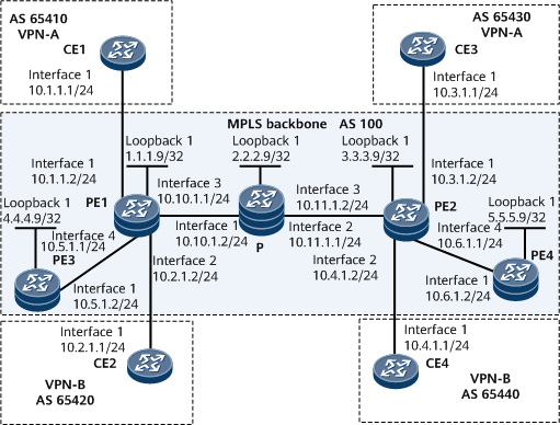
In Figure 1, PEs and the P node run IS-IS to implement connectivity between one another. The P node does not support MPLS LDP. PE1 and PE2 access both VPN-A and VPN-B. An LDP LSP originates from PE3 and is terminated at PE4 through a path PE1 > P > PE2.
VPN-A transmits EF and AF traffic. VPN-B transmits EF, AF, and BE traffic. The LDP LSP transmits BE traffic. QoS requirements of each type of traffic are as follows.
Data Flow |
Bandwidth |
|---|---|
VPN-A AF2 traffic |
100 Mbit/s |
VPN-A AF1 traffic |
50 Mbit/s |
VPN-B AF2 traffic |
100 Mbit/s |
VPN-B AF1 traffic |
50 Mbit/s |
VPN-B BE traffic |
50 Mbit/s |
LDP LSP BE traffic |
50 Mbit/s |
A DS-TE tunnel is established between PE1 and PE2 to transfer the preceding types of traffic and satisfy various QoS requirements. The bandwidth constraints model is set to RDM to allow CTi to preempt lower-priority CTj bandwidth (0 <= i < j <= 7) to guarantee higher-priority CT bandwidth.
Configuration Roadmap
The configuration roadmap is as follows:
- Since each tunnel can be configured with a single CT, establish a tunnel for LDP LSPs to carry CT0. Establish two tunnels in VPN-A, with each of them carrying a different CT, namely CT1 and CT2. Establish three tunnels in VPN-B, with each of them carrying a different CT, namely CT0, CT1, and CT2.
- Configure CT0, CT1, and CT2 to carry BE, AF1, and AF2 flows, respectively.
- Since the tunnels pass through the same path, configure the BCi link bandwidth value to be greater than or equal to the sum of CTi through CT7 bandwidth values of all TE tunnels, and configure the maximum link reservable bandwidth to be greater than or equal to the BC0 bandwidth value. Therefore, BC2 bandwidth ≥ Total AF2 bandwidth = 200 Mbit/s; BC1 bandwidth ≥ (BC2 bandwidth + Total AF1 bandwidth) = 300 Mbit/s; Reservable link bandwidth ≥ BC0 bandwidth ≥ (BC1 bandwidth + Total BE bandwidth) = 400 Mbit/s.
- Use a CT template to configure TE tunnels because the same type of service in different tunnels has the same bandwidth requirement.
Data Preparation
To complete the configuration, you need the following data:
- LSR IDs of PEs and the P
- Number of each MPLS TE tunnel interface
- TE-class mapping table
- Maximum reservable bandwidth value and each BC bandwidth value of each link
- VPN-A's and VPN-B's VPN instance names, route distinguishers, VPN-Targets, and tunnel policy name
Procedure
- Assign an IP address to each interface on the PEs and P and configure IS-IS to implement connectivity between the PEs and P.
For configuration details, see Configuration Files in this section.
After the configuration, IS-IS neighbor relationships can be established between PE1, P, and PE2. Run the display ip routing-table command. The command output shows that the PEs have learned the routes to Loopback 1 of each other.
- Configure an LSR ID and enable MPLS on each node; enable MPLS TE and RSVP-TE on PE1, PE2, and the P; enable MPLS LDP on each PE.
# Configure PE3.
<PE3> system-view
[~PE3] mpls lsr-id 4.4.4.9
[*PE3] mpls
[*PE3] commit
[~PE3-mpls] quit
[*PE3] mpls ldp
[*PE3] commit
[~PE3-mpls-ldp] quit
[~PE3] interface gigabitethernet 0/1/0
[*PE3-GigabitEthernet0/1/0] mpls
[*PE3-GigabitEthernet0/1/0] mpls ldp
[*PE3-GigabitEthernet0/1/0] commit
[~PE3-GigabitEthernet0/1/0] quit
# Configure PE1.
<PE1> system-view
[~PE1] mpls lsr-id 1.1.1.9
[*PE1] mpls
[*PE1-mpls] mpls te
[*PE1-mpls] mpls rsvp-te
[*PE1-mpls] commit
[~PE1-mpls] quit
[*PE1] mpls ldp
[*PE1-mpls-ldp] commit
[~PE1-mpls-ldp] quit
[~PE1] interface gigabitethernet 0/1/16
[*PE1-GigabitEthernet0/1/16] mpls
[*PE1-GigabitEthernet0/1/16] mpls te
[*PE1-GigabitEthernet0/1/16] mpls rsvp-te
[*PE1-GigabitEthernet0/1/16] commit
[~PE1-GigabitEthernet0/1/16] quit
[~PE1] interface gigabitethernet 0/1/24
[*PE1-GigabitEthernet0/1/24] mpls
[*PE1-GigabitEthernet0/1/24] mpls ldp
[*PE1-GigabitEthernet0/1/24] commit
[~PE1-GigabitEthernet0/1/24] quit
# Configure the P.
<P> system-view
[~P] mpls lsr-id 2.2.2.9
[*P] mpls
[*P-mpls] mpls te
[*P-mpls] mpls rsvp-te
[*P-mpls] commit
[~P-mpls] quit
[~P] interface gigabitethernet 0/1/0
[*P-GigabitEthernet0/1/0] mpls
[*P-GigabitEthernet0/1/0] mpls te
[*P-GigabitEthernet0/1/0] mpls rsvp-te
[*P-GigabitEthernet0/1/0] commit
[~P-GigabitEthernet0/1/0] quit
[~P] interface gigabitethernet 0/1/8
[*P-GigabitEthernet0/1/8] mpls
[*P-GigabitEthernet0/1/8] mpls te
[*P-GigabitEthernet0/1/8] mpls rsvp-te
[*P-GigabitEthernet0/1/8] commit
[~P-GigabitEthernet0/1/8] quit
# Configure PE2.
<PE2> system-view
[~PE2] mpls lsr-id 3.3.3.9
[*PE2] mpls
[*PE2-mpls] mpls te
[*PE2-mpls] mpls rsvp-te
[*PE2-mpls] commit
[~PE2-mpls] quit
[*PE2] mpls ldp
[*PE2-mpls] commit
[~PE2-mpls] quit
[~PE2] interface gigabitethernet 0/1/16
[*PE2-GigabitEthernet0/1/16] mpls
[*PE2-GigabitEthernet0/1/16] mpls te
[*PE2-GigabitEthernet0/1/16] mpls rsvp-te
[*PE2-GigabitEthernet0/1/16] commit
[~PE2-GigabitEthernet0/1/16] quit
[~PE2] interface gigabitethernet 0/1/24
[*PE2-GigabitEthernet0/1/24] mpls
[*PE2-GigabitEthernet0/1/24] mpls ldp
[*PE2-GigabitEthernet0/1/24] commit
[~PE2-GigabitEthernet0/1/24] quit
# Configure PE4.
<PE4> system-view
[~PE4] mpls lsr-id 5.5.5.9
[*PE4] mpls
[*PE4-mpls] commit
[~PE4-mpls] quit
[*PE4] mpls ldp
[*PE4-mpls] commit
[~PE4-mpls-ldp] quit
[~PE4] interface gigabitethernet 0/1/0
[*PE4-GigabitEthernet0/1/0] mpls
[*PE4-GigabitEthernet0/1/0] mpls ldp
[*PE4-GigabitEthernet0/1/0] commit
[~PE4-GigabitEthernet0/1/0] quit
After completing the configuration, run the display mpls rsvp-te interface command on PE1, PE2, or the P to view RSVP interface information and RSVP information. Run the display mpls ldp lsp command on PE1, PE2, PE3, or PE4. The command output shows that an LDP LSP has been established between the pair of PE3 and PE1 and that of PE2 and PE4.
- Configure IS-IS TE and enable CSPF on PE1, PE2, and the P.
# Enable IS-IS TE on all nodes and enable CSPF on the ingress of the TE tunnel.
# Configure PE1.
[~PE1] isis 1
[~PE1-isis-1] cost-style wide
[*PE1-isis-1] traffic-eng level-1-2
[*PE1-isis-1] commit
[~PE1-isis-1] quit
[~PE1] mpls
[~PE1-mpls] mpls te cspf
[*PE1-mpls] commit
# Configure the P.
[~P] isis 1
[~P-isis-1] cost-style wide
[*P-isis-1] traffic-eng level-1-2
[*P-isis-1] commit
[~P-isis-1] quit
# Configure PE2.
[~PE2] isis 1
[~PE2-isis-1] cost-style wide
[*PE2-isis-1] traffic-eng level-1-2
[*PE2-isis-1] commit
[~PE2-isis-1] quit
[~PE2] mpls
[~PE2-mpls] mpls te cspf
[*PE2-mpls] commit
[~PE2-mpls] quit
After completing the configuration, run the display isis lsdb command on a PE or the P. The command output shows that the IS-IS link status information.
- Configure a DS-TE mode and a BCM on PE1, PE2, and the P.
# Configure PE1.
[~PE1] mpls
[~PE1-mpls] mpls te ds-te mode ietf
[*PE1-mpls] mpls te ds-te bcm rdm
[*PE1-mpls] commit
[~PE1-mpls] quit
# Configure the P.
[~P] mpls
[~P-mpls] mpls te ds-te mode ietf
[*P-mpls] mpls te ds-te bcm rdm
[*P-mpls] commit
[~P-mpls] quit
# Configure PE2.
[~PE2] mpls
[~PE2-mpls] mpls te ds-te mode ietf
[*PE2-mpls] mpls te ds-te bcm rdm
[*PE2-mpls] commit
[~PE2-mpls] quit
After completing the configuration, run the display mpls te ds-te summary command on a PE or the P to view DS-TE configurations. The following example uses the command output on PE1.
[~PE1] display mpls te ds-te summary DS-TE IETF Supported :YES DS-TE MODE :IETF Bandwidth Constraint Model :RDM TEClass Mapping (configured): TE-Class ID Class Type Priority TE-Class 0 0 0 TE-Class 1 1 0 TE-Class 2 2 0 TE-Class 3 3 0 TE-Class 4 0 7 TE-Class 5 1 7 TE-Class 6 2 7 TE-Class 7 3 7 - Configure link bandwidth values on PE1, PE2, and the P.
# Configure PE1.
[~PE1] interface gigabitethernet 0/1/16
[~PE1-GigabitEthernet0/1/16] mpls te bandwidth max-reservable-bandwidth 400000
[*PE1-GigabitEthernet0/1/16] mpls te bandwidth bc0 400000 bc1 300000 bc2 200000
[*PE1-GigabitEthernet0/1/16] commit
[~PE1-GigabitEthernet0/1/16] quit
# Configure the P.
[~P] interface gigabitethernet 0/1/0
[~P-GigabitEthernet0/1/0] mpls te bandwidth max-reservable-bandwidth 400000
[*P-GigabitEthernet0/1/0] mpls te bandwidth bc0 400000 bc1 300000 bc2 200000
[*P-GigabitEthernet0/1/0] commit
[~P-GigabitEthernet0/1/0] quit
[~P] interface gigabitethernet 0/1/8
[~P-GigabitEthernet0/1/8] mpls te bandwidth max-reservable-bandwidth 400000
[*P-GigabitEthernet0/1/8] mpls te bandwidth bc0 400000 bc1 300000 bc2 200000
[~P-GigabitEthernet0/1/8] quit
# Configure PE2.
[~PE2] interface gigabitethernet 0/1/16
[~PE2-GigabitEthernet0/1/16] mpls te bandwidth max-reservable-bandwidth 400000
[*PE2-GigabitEthernet0/1/16] mpls te bandwidth bc0 400000 bc1 300000 bc2 200000
[~PE2-GigabitEthernet0/1/16] quit
After completing the configuration, run the display mpls te link-administration bandwidth-allocation interface gigabitethernet command on a PE to view BC bandwidth allocation information. The following example uses the command output on PE1.
[~PE1] display mpls te link-administration bandwidth-allocation interface gigabitethernet 0/1/16
  Link ID:  GigabitEthernet0/1/16
  Bandwidth Constraint Model   :  Russian Dolls Model (RDM)
  Physical Link Bandwidth(Kbits/sec)         :  -
  Maximum Link Reservable Bandwidth(Kbit/sec):  400000
  Reservable Bandwidth BC0(Kbit/sec)         :  400000
  Reservable Bandwidth BC1(Kbit/sec)         :  300000
  Reservable Bandwidth BC2(Kbit/sec)         :  200000
  Reservable Bandwidth BC3(Kbit/sec)         :  0
  Reservable Bandwidth BC4(Kbit/sec)         :  0
  Reservable Bandwidth BC5(Kbit/sec)         :  0
  Reservable Bandwidth BC6(Kbit/sec)         :  0
  Reservable Bandwidth BC7(Kbit/sec)         :  0
  Downstream Bandwidth (Kbit/sec)           :   0
  IPUpdown Link Status                       :  UP
  PhysicalUpdown Link Status                 :  UP
  ----------------------------------------------------------------------
  TE-CLASS  CT    PRIORITY   BW RESERVED   BW AVAILABLE   DOWNSTREAM
                             (Kbit/sec)     (Kbit/sec) RSVPLSPNODE COUNT
  ----------------------------------------------------------------------
     0      0        0           0             400000           0
     1      1        0           0             300000           0
     2      2        0           0             200000           0
     3      0        7           0             400000           0
     4      1        7           0             300000           0
     5      2        7           0             200000           0
     6      -        -           -             -                -
     7      -        -           -             -                -
     8      -        -           -             -                -
     9      -        -           -             -                -
     10     -        -           -             -                -
     11     -        -           -             -                -
     12     -        -           -             -                -
     13     -        -           -             -                -
     14     -        -           -             -                -
     15     -        -           -             -                -
  ----------------------------------------------------------------------
- Configure a TE-class mapping table on a PE.
# Configure PE1.
[~PE1] te-class-mapping
[~PE1-te-class-mapping] te-class0 class-type ct0 priority 0 description For-BE
[*PE1-te-class-mapping] te-class1 class-type ct1 priority 0 description For-AF1
[*PE1-te-class-mapping] te-class2 class-type ct2 priority 0 description For-AF2
[*PE1-te-class-mapping] commit
[~PE1-te-class-mapping] quit
# Configure PE2.
[~PE2] te-class-mapping
[~PE2-te-class-mapping] te-class0 class-type ct0 priority 0 description For-BE
[*PE2-te-class-mapping] te-class1 class-type ct1 priority 0 description For-AF1
[*PE2-te-class-mapping] te-class2 class-type ct2 priority 0 description For-AF2
[*PE2-te-class-mapping] commit
[~PE2-te-class-mapping] quit
After completing the configuration, run the display mpls te ds-te te-class-mapping command on a PE to view TE-class mapping table information. The following example uses the command output on PE1.
[~PE1] display mpls te ds-te te-class-mapping TE-Class ID Class Type Priority Description TE-Class0 0 0 For-BE TE-Class1 1 0 For-AF1 TE-Class2 2 0 For-AF2 TE-Class3 - - - TE-Class4 - - - TE-Class5 - - - TE-Class6 - - - TE-Class7 - - - - Configure an explicit path on PE1 and PE2.
# Configure PE1.
[~PE1] explicit-path path1
[*PE1-explicit-path-path1] next hop 10.10.1.2
[*PE1-explicit-path-path1] next hop 10.11.1.2
[*PE1-explicit-path-path1] next hop 3.3.3.9
[*PE1-explicit-path-path1] commit
[~PE1-explicit-path-path1] quit
# Configure PE2.
[~PE2] explicit-path path1
[*PE2-explicit-path-path1] next hop 10.11.1.1
[*PE2-explicit-path-path1] next hop 10.10.1.1
[*PE2-explicit-path-path1] next hop 1.1.1.9
[*PE2-explicit-path-path1] commit
[~PE2-explicit-path-path1] quit
After completing the configuration, run the display explicit-path command on a PE to view explicit path information. The following example uses the command output on PE1.
[~PE1] display explicit-path path1 Path Name : path1 Path Status : Enabled 1 10.10.1.2 Strict Include 2 10.11.1.2 Strict Include 3 3.3.3.9 Strict Include - Configure a tunnel interface on PE1 and PE2.
# Configure PE1.
[~PE1] interface tunnel10
[*PE1-Tunnel10] description For VPN-A & Non-VPN
[*PE1-Tunnel10] ip address unnumbered interface loopback 1
[*PE1-Tunnel10] tunnel-protocol mpls te
[*PE1-Tunnel10] destination 3.3.3.9
[*PE1-Tunnel10] mpls te tunnel-id 10
[*PE1-Tunnel10] mpls te signal-protocol rsvp-te
[*PE1-Tunnel10] mpls te path explicit-path path1
[*PE1-Tunnel10] mpls te priority 0 0
[*PE1-Tunnel10] mpls te bandwidth ct0 50000
[*PE1-Tunnel10] mpls te reserved-for-binding
[*PE1-Tunnel10] commit
[~PE1-Tunnel10] quit
[~PE1] interface tunnel11
[*PE1-Tunnel11] description For VPN-A & Non-VPN
[*PE1-Tunnel11] ip address unnumbered interface loopback 1
[*PE1-Tunnel11] tunnel-protocol mpls te
[*PE1-Tunnel11] destination 3.3.3.9
[*PE1-Tunnel11] mpls te tunnel-id 11
[*PE1-Tunnel11] mpls te signal-protocol rsvp-te
[*PE1-Tunnel11] mpls te path explicit-path path1
[*PE1-Tunnel11] mpls te priority 0 0
[*PE1-Tunnel11] mpls te bandwidth ct1 50000
[*PE1-Tunnel11] mpls te reserved-for-binding
[*PE1-Tunnel11] commit
[~PE1-Tunnel11] quit
[~PE1] interface tunnel12
[*PE1-Tunnel12] description For VPN-A & Non-VPN
[*PE1-Tunnel12] ip address unnumbered interface loopback 1
[*PE1-Tunnel12] tunnel-protocol mpls te
[*PE1-Tunnel12] destination 3.3.3.9
[*PE1-Tunnel12] mpls te tunnel-id 12
[*PE1-Tunnel12] mpls te signal-protocol rsvp-te
[*PE1-Tunnel12] mpls te path explicit-path path1
[*PE1-Tunnel12] mpls te priority 0 0
[*PE1-Tunnel12] mpls te bandwidth ct2 100000
[*PE1-Tunnel12] mpls te reserved-for-binding
[*PE1-Tunnel12] commit
[~PE1-Tunnel12] quit
[~PE1] interface tunnel20
[*PE1-Tunnel20] description For VPN-B
[*PE1-Tunnel20] ip address unnumbered interface loopback 1
[*PE1-Tunnel20] tunnel-protocol mpls te
[*PE1-Tunnel20] destination 3.3.3.9
[*PE1-Tunnel20] mpls te tunnel-id 20
[*PE1-Tunnel20] mpls te signal-protocol rsvp-te
[*PE1-Tunnel20] mpls te path explicit-path path1
[*PE1-Tunnel20] mpls te priority 0 0
[*PE1-Tunnel20] mpls te bandwidth ct0 50000
[*PE1-Tunnel20] mpls te reserved-for-binding
[*PE1-Tunnel20] commit
[~PE1-Tunnel20] quit
[~PE1] interface tunnel21
[*PE1-Tunnel21] description For VPN-B
[*PE1-Tunnel21] ip address unnumbered interface loopback 1
[*PE1-Tunnel21] tunnel-protocol mpls te
[*PE1-Tunnel21] destination 3.3.3.9
[*PE1-Tunnel21] mpls te tunnel-id 21
[*PE1-Tunnel21] mpls te signal-protocol rsvp-te
[*PE1-Tunnel21] mpls te path explicit-path path1
[*PE1-Tunnel21] mpls te priority 0 0
[*PE1-Tunnel21] mpls te bandwidth ct1 50000
[*PE1-Tunnel21] mpls te reserved-for-binding
[*PE1-Tunnel21] commit
[~PE1-Tunnel21] quit
[~PE1] interface tunnel22
[*PE1-Tunnel22] description For VPN-B
[*PE1-Tunnel22] ip address unnumbered interface loopback 1
[*PE1-Tunnel22] tunnel-protocol mpls te
[*PE1-Tunnel22] destination 3.3.3.9
[*PE1-Tunnel22] mpls te tunnel-id 22
[*PE1-Tunnel22] mpls te signal-protocol rsvp-te
[*PE1-Tunnel22] mpls te path explicit-path path1
[*PE1-Tunnel22] mpls te priority 0 0
[*PE1-Tunnel22] mpls te bandwidth ct2 100000
[*PE1-Tunnel22] mpls te reserved-for-binding
[*PE1-Tunnel22] commit
[~PE1-Tunnel22] quit
# Configure PE2.
[~PE2] interface tunnel10
[*PE2-Tunnel10] description For VPN-A & Non-VPN
[*PE2-Tunnel10] ip address unnumbered interface loopback 1
[*PE2-Tunnel10] tunnel-protocol mpls te
[*PE2-Tunnel10] destination 1.1.1.9
[*PE2-Tunnel10] mpls te tunnel-id 10
[*PE2-Tunnel10] mpls te signal-protocol rsvp-te
[*PE2-Tunnel10] mpls te path explicit-path path1
[*PE2-Tunnel10] mpls te priority 0 0
[*PE2-Tunnel10] mpls te bandwidth ct0 50000
[*PE2-Tunnel10] mpls te reserved-for-binding
[*PE2-Tunnel10] commit
[~PE2-Tunnel10] quit
[~PE2] interface tunnel11
[*PE2-Tunnel11] description For VPN-A & Non-VPN
[*PE2-Tunnel11] ip address unnumbered interface loopback 1
[*PE2-Tunnel11] tunnel-protocol mpls te
[*PE2-Tunnel11] destination 1.1.1.9
[*PE2-Tunnel11] mpls te tunnel-id 11
[*PE2-Tunnel11] mpls te signal-protocol rsvp-te
[*PE2-Tunnel11] mpls te path explicit-path path1
[*PE2-Tunnel11] mpls te priority 0 0
[*PE2-Tunnel11] mpls te bandwidth ct1 50000
[*PE2-Tunnel11] mpls te reserved-for-binding
[*PE2-Tunnel11] commit
[~PE2-Tunnel11] quit
[~PE2] interface tunnel12
[*PE2-Tunnel12] description For VPN-A & Non-VPN
[*PE2-Tunnel12] ip address unnumbered interface loopback 1
[*PE2-Tunnel12] tunnel-protocol mpls te
[*PE2-Tunnel12] destination 1.1.1.9
[*PE2-Tunnel12] mpls te tunnel-id 12
[*PE2-Tunnel12] mpls te signal-protocol rsvp-te
[*PE2-Tunnel12] mpls te path explicit-path path1
[*PE2-Tunnel12] mpls te priority 0 0
[*PE2-Tunnel12] mpls te bandwidth ct2 100000
[*PE2-Tunnel12] mpls te reserved-for-binding
[*PE2-Tunnel12] commit
[~PE2-Tunnel12] quit
[~PE2] interface tunnel20
[*PE2-Tunnel20] description For VPN-B
[*PE2-Tunnel20] ip address unnumbered interface loopback 1
[*PE2-Tunnel20] tunnel-protocol mpls te
[*PE2-Tunnel20] destination 1.1.1.9
[*PE2-Tunnel20] mpls te tunnel-id 20
[*PE2-Tunnel20] mpls te signal-protocol rsvp-te
[*PE2-Tunnel20] mpls te path explicit-path path1
[*PE2-Tunnel20] mpls te priority 0 0
[*PE2-Tunnel20] mpls te bandwidth ct0 50000
[*PE2-Tunnel20] mpls te reserved-for-binding
[*PE2-Tunnel20] commit
[~PE2-Tunnel20] quit
[~PE2] interface tunnel21
[*PE2-Tunnel21] description For VPN-B
[*PE2-Tunnel21] ip address unnumbered interface loopback 1
[*PE2-Tunnel21] tunnel-protocol mpls te
[*PE2-Tunnel21] destination 1.1.1.9
[*PE2-Tunnel21] mpls te tunnel-id 21
[*PE2-Tunnel21] mpls te signal-protocol rsvp-te
[*PE2-Tunnel21] mpls te path explicit-path path1
[*PE2-Tunnel21] mpls te priority 0 0
[*PE2-Tunnel21] mpls te bandwidth ct1 50000
[*PE2-Tunnel21] mpls te reserved-for-binding
[*PE2-Tunnel21] commit
[~PE2-Tunnel21] quit
[~PE2] interface tunnel22
[*PE2-Tunnel22] description For VPN-B
[*PE2-Tunnel22] ip address unnumbered interface loopback 1
[*PE2-Tunnel22] tunnel-protocol mpls te
[*PE2-Tunnel22] destination 1.1.1.9
[*PE2-Tunnel22] mpls te tunnel-id 2
[*PE2-Tunnel22] mpls te signal-protocol rsvp-te
[*PE2-Tunnel22] mpls te path explicit-path path1
[*PE2-Tunnel22] mpls te priority 0 0
[*PE2-Tunnel22] mpls te bandwidth ct2 100000
[*PE2-Tunnel22] mpls te reserved-for-binding
[*PE2-Tunnel22] commit
[~PE2-Tunnel22] quit
After completing the configuration, run the display interface tunnel interface-number command on a PE to check whether the tunnel interface state is Up. The following example the command output for Tunnel10 of PE1.
[~PE1] display interface tunnel10
Tunnel1 current state : UP(ifindex: 27)
Line protocol current state : UP
Description: For VPN-A & Non-VPN
Route Port,The Maximum Transmit Unit is 1500
Internet Address is unnumbered, using address of LoopBack0(1.1.1.9/32)
Encapsulation is TUNNEL, loopback not set
Tunnel destination 3.3.3.9
Tunnel up/down statistics 0
Tunnel ct0 bandwidth is 0 Kbit/sec
Tunnel protocol/transport MPLS/MPLS, ILM is disabled
primary tunnel id is 0x0, secondary tunnel id is 0x0
Current system time: 2017-07-19 06:46:59
    0 seconds output rate 0 bits/sec, 0 packets/sec
    0 seconds output rate 0 bits/sec, 0 packets/sec
    0 packets output,  0 bytes
    0 output error
    0 output drop
    Last 300 seconds input utility rate:  --
    Last 300 seconds output utility rate: --
Run the display mpls te te-class-tunnel command on a PE to view information about a TE tunnel associated with a TE-class. The following example uses the command output on PE1.
[~PE1] display mpls te te-class-tunnel ct0 priority 0 ---------------------------------------------------------- No. CT priority status tunnel name ---------------------------------------------------------- 1 0 0 Valid Tunnel10 2 0 0 Valid Tunnel20 - Establish an MP-IBGP peer relationship between the PEs, and establish EBGP peer relationships between PEs and CEs.
# Configure PE1.
[~PE1] bgp 100
[*PE1-bgp] peer 3.3.3.9 as-number 100
[*PE1-bgp] peer 3.3.3.9 connect-interface loopback 1
[*PE1-bgp] ipv4-family vpnv4
[*PE1-bgp-af-vpnv4] peer 3.3.3.9 enable
[*PE1-bgp-af-vpnv4] commit
[~PE1-bgp-af-vpnv4] quit
[~PE1-bgp] ipv4-family vpn-instance vpna
[*PE1-bgp-vpna] peer 10.1.1.1 as-number 65410
[*PE1-bgp-vpna] import-route direct
[*PE1-bgp-vpna] commit
[~PE1-bgp-vpna] quit
[~PE1-bgp] ipv4-family vpn-instance vpnb
[*PE1-bgp-vpnb] peer 10.2.1.1 as-number 65420
[*PE1-bgp-vpnb] import-route direct
[*PE1-bgp-vpnb] commit
[~PE1-bgp-vpnb] quit

The procedures for configuring PE2 are similar to that of PE1. For configuration details, see Configuration Files in this section.
# Configure CE1.
[~CE1] bgp 65410
[*CE1-bgp] peer 10.1.1.2 as-number 100
[*CE1-bgp] import-route direct
[*CE1-bgp] commit
After completing the configuration, run the display bgp vpnv4 all peer command on each PE. The command output shows that BGP peer relationships between PEs have been established and are in the Established state.
[~PE1] display bgp vpnv4 all peer BGP local router ID : 1.1.1.9 Local AS number : 100 Total number of peers : 3 Peers in established state : 3 Peer V AS MsgRcvd MsgSent OutQ Up/Down State PrefRcv 3.3.3.9 4 100 12 18 0 00:09:38 Established 0 Peer of vpn instance: VPN-Instance vpna, Router ID 1.1.1.9: 10.1.1.1 4 65410 25 25 0 00:17:57 Established 1 VPN-Instance vpnb, Router ID 1.1.1.9: 10.2.1.1 4 65420 21 22 0 00:17:10 Established 1 - Configure tunnel policies on PEs.
# Configure PE1.
[~PE1] tunnel-policy policya
[*PE1-tunnel-policy-policya] tunnel binding destination 3.3.3.9 te tunnel 10 tunnel 11 tunnel 12
[*PE1-tunnel-policy-policya] commit
[~PE1-tunnel-policy-policya] quit
[~PE1] tunnel-policy policyb
[*PE1-tunnel-policy-policyb] tunnel binding destination 3.3.3.9 te tunnel 20 tunnel 21 tunnel 22
[*PE1-tunnel-policy-policyb] commit
[~PE1-tunnel-policy-policyb] quit
# Configure PE2.
[~PE2] tunnel-policy policya
[*PE2-tunnel-policy-policya] tunnel binding destination 1.1.1.9 te tunnel 10 tunnel 11 tunnel 12
[*PE2-tunnel-policy-policya] commit
[~PE2-tunnel-policy-policya] quit
[~PE2] tunnel-policy policyb
[*PE2-tunnel-policy-policyb] tunnel binding destination 1.1.1.9 te tunnel 20 tunnel 21 tunnel 22
[*PE2-tunnel-policy-policyb] commit
[~PE2-tunnel-policy-policyb] quit
- Configure VPN instances on each PE and configure CEs to access the PEs.
# Configure PE1.
[~PE1] ip vpn-instance vpna
[*PE1-vpn-instance-vpna] ipv4-family
[*PE1-vpn-instance-vpna-af-ipv4] route-distinguisher 100:1
[*PE1-vpn-instance-vpna-af-ipv4] vpn-target 111:1 both
[*PE1-vpn-instance-vpna-af-ipv4] tnl-policy policya
[*PE1-vpn-instance-vpna-af-ipv4] commit
[~PE1-vpn-instance-vpna-af-ipv4] quit
[~PE1-vpn-instance-vpna] quit
[~PE1] ip vpn-instance vpnb
[*PE1-vpn-instance-vpna] ipv4-family
[*PE1-vpn-instance-vpnb-af-ipv4] route-distinguisher 100:2
[*PE1-vpn-instance-vpnb-af-ipv4] vpn-target 222:2 both
[*PE1-vpn-instance-vpnb-af-ipv4] tnl-policy policyb
[*PE1-vpn-instance-vpnb-af-ipv4] commit
[~PE1-vpn-instance-vpnb-af-ipv4] quit
[~PE1-vpn-instance-vpnb] quit
[~PE1] interface gigabitethernet 0/1/0
[*PE1-GigabitEthernet0/1/0] ip binding vpn-instance vpna
[*PE1-GigabitEthernet0/1/0] ip address 10.1.1.2 24
[*PE1-GigabitEthernet0/1/0] commit
[~PE1-GigabitEthernet0/1/0] quit
[*PE1] interface gigabitethernet 0/1/8
[*PE1-GigabitEthernet0/1/8] ip binding vpn-instance vpnb
[*PE1-GigabitEthernet0/1/8] ip address 10.2.1.2 24
[*PE1-GigabitEthernet0/1/8] commit
[~PE1-GigabitEthernet0/1/8] quit
# Configure PE2.
[~PE2] ip vpn-instance vpna
[*PE2-vpn-instance-vpna] ipv4-family
[*PE2-vpn-instance-vpna-af-ipv4] route-distinguisher 200:1
[*PE2-vpn-instance-vpna-af-ipv4] vpn-target 111:1 both
[*PE2-vpn-instance-vpna-af-ipv4] tnl-policy policya
[*PE2-vpn-instance-vpna-af-ipv4] commit
[~PE2-vpn-instance-vpna-af-ipv4] quit
[~PE2-vpn-instance-vpna] quit
[~PE2] ip vpn-instance vpnb
[*PE2-vpn-instance-vpnb] ipv4-family
[*PE2-vpn-instance-vpnb-af-ipv4] route-distinguisher 200:2
[*PE2-vpn-instance-vpnb-af-ipv4] vpn-target 222:2 both
[*PE2-vpn-instance-vpnb-af-ipv4] tnl-policy policyb
[*PE2-vpn-instance-vpnb-af-ipv4] commit
[~PE2-vpn-instance-vpnb-af-ipv4] quit
[~PE2-vpn-instance-vpnb] quit
[~PE2] interface gigabitethernet 0/1/0
[*PE2-GigabitEthernet0/1/0] ip binding vpn-instance vpna
[*PE2-GigabitEthernet0/1/0] ip address 10.3.1.2 24
[*PE2-GigabitEthernet0/1/0] commit
[~PE2-GigabitEthernet0/1/0] quit
[~PE2] interface gigabitethernet 0/1/8
[*PE2-GigabitEthernet0/1/8] ip binding vpn-instance vpnb
[*PE2-GigabitEthernet0/1/8] ip address 10.4.1.2 24
[*PE2-GigabitEthernet0/1/8] commit
[~PE2-GigabitEthernet0/1/8] quit
# Assign IP addresses to the interfaces on CEs. For configuration details, see Configuration Files in this section.
After completing the configuration, run the display ip vpn-instance verbose command on a PE to view the configurations of VPN instances. Each PE can successfully ping its connected CEs.
Configuration Files
PE1 configuration file
#
 sysname PE1
#
ip vpn-instance vpna
 ipv4-family
  route-distinguisher 100:1
  tnl-policy policya
  apply-label per-instance
  vpn-target 111:1 export-extcommunity
  vpn-target 111:1 import-extcommunity
#
ip vpn-instance vpnb
 ipv4-family
  route-distinguisher 100:2
  tnl-policy policyb
  apply-label per-instance
  vpn-target 222:2 export-extcommunity
  vpn-target 222:2 import-extcommunity
#
 mpls lsr-id 1.1.1.9
#
 mpls
  mpls te
  mpls te ds-te mode ietf
  mpls rsvp-te
#
 mpls ldp
#
 mpls ldp remote-peer pe1tope2
  remote-ip 3.3.3.9
#
 explicit-path path1
  next hop 10.10.1.2
  next hop 10.11.1.2
  next hop 3.3.3.9
#
 te-class-mapping
  te-class0 class-type ct0 priority 0 description For-BE
 te-class1 class-type ct1 priority 0 description For-AF1
 te-class2 class-type ct2 priority 0 description For-AF2
#
interface Tunnel10
 description For VPN-A & Non-VPN
 ip address unnumbered interface LoopBack1
 tunnel-protocol mpls te
 destination 3.3.3.9
 mpls te tunnel-id 10
 mpls te priority 0
 mpls te bandwidth ct0 50000
 mpls te reserved-for-binding
 mpls te path explicit-path path1
 mpls te igp advertise
 mpls te igp metric absolute 1
#
interface Tunnel11
 description For VPN-A & Non-VPN
 ip address unnumbered interface LoopBack1
 tunnel-protocol mpls te
 destination 3.3.3.9
 mpls te tunnel-id 11
 mpls te priority 0
 mpls te bandwidth ct1 50000
 mpls te reserved-for-binding
 mpls te path explicit-path path1
 mpls te igp advertise
 mpls te igp metric absolute 1
#
interface Tunnel12
 description For VPN-A & Non-VPN
 ip address unnumbered interface LoopBack1
 tunnel-protocol mpls te
 destination 3.3.3.9
 mpls te tunnel-id 12
 mpls te priority 0
 mpls te bandwidth ct2 100000
 mpls te reserved-for-binding
 mpls te path explicit-path path1
 mpls te igp advertise
 mpls te igp metric absolute 1
#
interface Tunnel20
 description For VPN-B
 ip address unnumbered interface LoopBack1
 tunnel-protocol mpls te
 destination 3.3.3.9
 mpls te tunnel-id 20
 mpls te priority 0
 mpls te bandwidth ct0 50000
 mpls te reserved-for-binding
 mpls te path explicit-path path1
#
interface Tunnel21
 description For VPN-B
 ip address unnumbered interface LoopBack1
 tunnel-protocol mpls te
 destination 3.3.3.9
 mpls te tunnel-id 21
 mpls te priority 0
 mpls te bandwidth ct1 50000
 mpls te reserved-for-binding
 mpls te path explicit-path path1
#
interface Tunnel22
 description For VPN-B
 ip address unnumbered interface LoopBack1
 tunnel-protocol mpls te
 destination 3.3.3.9
 mpls te tunnel-id 22
 mpls te priority 0
 mpls te bandwidth ct2 100000
 mpls te reserved-for-binding
 mpls te path explicit-path path1
#
bgp 100
 peer 3.3.3.9 as-number 100
 peer 3.3.3.9 connect-interface LoopBack1
 #
 ipv4-family unicast
  undo synchronization
  peer 3.3.3.9 enable
#
 ipv4-family vpnv4
  policy vpn-target
  peer 3.3.3.9 enable
 #
 ipv4-family vpn-instance vpna
  peer 10.1.1.1 as-number 65410
  import-route direct
#
 ipv4-family vpn-instance vpnb
  peer 10.2.1.1 as-number 65420
  import-route direct
#
isis 1
 is-level level-1
 cost-style wide
 traffic-eng level-1
#
tunnel-policy policya
 tunnel binding destination 3.3.3.9 te Tunnel10 Tunnel11 Tunnel12
#
tunnel-policy policyb
 tunnel binding destination 3.3.3.9 te Tunnel20 Tunnel21 Tunnel22
#
return
P configuration file
#
 sysname P
#
 mpls lsr-id 2.2.2.9
#
 mpls
  mpls te
  mpls te ds-te mode ietf
  mpls rsvp-te
#
interface GigabitEthernet0/1/0
 undo shutdown
 ip address 10.10.1.2 255.255.255.0
 mpls
 mpls te
 mpls te bandwidth max-reservable-bandwidth 400000
 mpls te bandwidth bc0 400000 bc1 300000 bc2 200000
 mpls rsvp-te
#
interface GigabitEthernet0/1/8
 undo shutdown
 ip address 10.11.1.1 255.255.255.0
 mpls
 mpls te
 mpls te bandwidth max-reservable-bandwidth 400000
 mpls te bandwidth bc0 400000 bc1 300000 bc2 200000
 mpls rsvp-te
#
interface LoopBack1
 ip address 2.2.2.9 255.255.255.255
#
isis 1
 is-level level-1
 cost-style wide
 traffic-eng level-1
#
return
PE2 configuration file
#
 sysname PE2
#
ip vpn-instance vpna
 ipv4-family
  route-distinguisher 200:1
  tnl-policy policya
  apply-label per-instance
  vpn-target 111:1 export-extcommunity
  vpn-target 111:1 import-extcommunity
#
ip vpn-instance vpnb
 ipv4-family
  route-distinguisher 200:2
  tnl-policy policyb
  apply-label per-instance
  vpn-target 222:2 export-extcommunity
  vpn-target 222:2 import-extcommunity
#
mpls lsr-id 3.3.3.9
#
 mpls
  mpls te
  mpls te ds-te mode ietf
 mpls te rsvp-te
#
 mpls ldp
#
mpls ldp remote-peer pe2tope1
 remote-ip 1.1.1.9
#
 explicit-path path1
 next hop 10.10.1.1
 next hop 10.11.1.1
 next hop 1.1.1.9
#
 te-class-mapping
  te-class0 class-type ct0 priority 0 description For-BE
 te-class1 class-type ct1 priority 0 description For-AF1
 te-class2 class-type ct2 priority 0 description For-AF2
#
interface LoopBack1
 ip address 3.3.3.9 255.255.255.255
#
interface Tunnel10
 description For VPN-A & Non-VPN
 ip address unnumbered interface LoopBack1
 tunnel-protocol mpls te
 destination 1.1.1.9
 mpls te tunnel-id 10
 mpls te priority 0
 mpls te bandwidth ct0 50000
 mpls te reserved-for-binding
 mpls te path explicit-path path1
 mpls te igp advertise
 mpls te igp metric absolute 1
#
interface Tunnel11
 description For VPN-A & Non-VPN
 ip address unnumbered interface LoopBack1
 tunnel-protocol mpls te
 destination 1.1.1.9
 mpls te tunnel-id 11
 mpls te priority 0
 mpls te bandwidth ct1 50000
 mpls te reserved-for-binding
 mpls te path explicit-path path1
 mpls te igp advertise
 mpls te igp metric absolute 1
#
interface Tunnel12
 description For VPN-A & Non-VPN
 ip address unnumbered interface LoopBack1
 tunnel-protocol mpls te
 destination 1.1.1.9
 mpls te tunnel-id 12
 mpls te priority 0
 mpls te bandwidth ct2 100000
 mpls te reserved-for-binding
 mpls te path explicit-path path1
 mpls te igp advertise
 mpls te igp metric absolute 1
#
interface Tunnel20
 description For VPN-B
 ip address unnumbered interface LoopBack1
 tunnel-protocol mpls te
 destination 1.1.1.9
 mpls te tunnel-id 20
 mpls te priority 0
 mpls te bandwidth ct0 50000
 mpls te reserved-for-binding
 mpls te path explicit-path path1
#
interface Tunnel21
 description For VPN-B
 ip address unnumbered interface LoopBack1
 tunnel-protocol mpls te
 destination 1.1.1.9
 mpls te tunnel-id 21
 mpls te priority 0
 mpls te bandwidth ct1 50000
 mpls te reserved-for-binding
 mpls te path explicit-path path1
#
interface Tunnel22
 description For VPN-B
 ip address unnumbered interface LoopBack1
 tunnel-protocol mpls te
 destination 1.1.1.9
 mpls te tunnel-id 22
 mpls te priority 0
 mpls te bandwidth ct2 100000
 mpls te reserved-for-binding
 mpls te path explicit-path path1
#
bgp 100
 peer 1.1.1.9 as-number 100
 peer 1.1.1.9 connect-interface LoopBack1
#
 ipv4-family unicast
  undo synchronization
  peer 1.1.1.9 enable
#
 ipv4-family vpnv4
  policy vpn-target
  peer 1.1.1.9 enable
#
 ipv4-family vpn-instance vpna
  peer 10.3.1.1 as-number 65430
  import-route direct
#
 ipv4-family vpn-instance vpnb
  peer 10.4.1.1 as-number 65440
  import-route direct
#
isis 1
 is-level level-1
 cost-style wide
 traffic-eng level-1
#
tunnel-policy policya
 tunnel binding destination 1.1.1.9 te Tunnel10 Tunnel11 Tunnel12
#
tunnel-policy policyb
 tunnel binding destination 1.1.1.9 te Tunnel20 Tunnel21 Tunnel22
#
return
- PE3 configuration file
#
 sysname PE3
#
 mpls lsr-id 4.4.4.9
#
mpls
#
 mpls ldp
#
interface GigabitEthernet0/1/0
 undo shutdown
 ip address 10.5.1.2 255.255.255.0
 mpls
 mpls ldp
#
interface LoopBack1
 ip address 4.4.4.9 255.255.255.255
#
isis 1
 is-level level-1
 cost-style wide
 traffic-eng level-1
#
return
PE4 configuration file
#
 sysname PE4
#
 mpls lsr-id 5.5.5.9
#
mpls
#
 mpls ldp
#
interface GigabitEthernet0/1/0
 undo shutdown
 ip address 10.6.1.2 255.255.255.0
 mpls
 mpls ldp
#
interface LoopBack1
 ip address 5.5.5.9 255.255.255.255
#
isis 1
 is-level level-1
 cost-style wide
 traffic-eng level-1
#
return
CE1 configuration file
#
 sysname CE1
#
interface GigabitEthernet0/1/0
 undo shutdown
 ip address 10.1.1.1 255.255.255.0
#
bgp 65410
 peer 10.1.1.2 as-number 100
 #
 ipv4-family unicast
  undo synchronization
  import-route direct
  peer 10.1.1.2 enable
#
return
CE2 configuration file
#
 sysname CE2
#
interface GigabitEthernet0/1/0
 undo shutdown
 ip address 10.2.1.1 255.255.255.0
#
bgp 65420
 peer 10.2.1.2 as-number 100
 #
 ipv4-family unicast
  undo synchronization
  import-route direct
  peer 10.2.1.2 enable
#
return
CE3 configuration file
#
 sysname CE3
#
interface GigabitEthernet0/1/0
 undo shutdown
 ip address 10.3.1.1 255.255.255.0
#
bgp 65430
 peer 10.3.1.2 as-number 100
 #
 ipv4-family unicast
  undo synchronization
  import-route direct
  peer 10.3.1.2 enable
#
return
CE4 configuration file
#
 sysname CE4
#
interface GigabitEthernet0/1/0
 undo shutdown
 ip address 10.4.1.1 255.255.255.0
#
bgp 65440
 peer 10.4.1.2 as-number 100
 #
 ipv4-family unicast
  undo synchronization
  import-route direct
  peer 10.4.1.2 enable
#
return