Example for Configuring CBTS in an L3VPN over TE Scenario
Networking Requirements
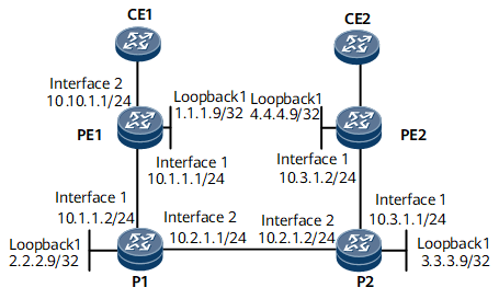
In Figure 1, CE1 and CE2 belong to the same L3VPN. They access the public network through PE1 and PE2 respectively. Various types of services are transmitted between CE1 and CE2. Transmitting a large number of common services deteriorates the efficiency of transmitting important services. To prevent this problem, the CBTS function can be configured. A CBTS allows traffic of a specific service class to be transmitted along a specified tunnel.
In this example, tunnel 1 and tunnel 2 on PE1 transmit important services, and tunnel 3 transmits other packets.

After the CBTS function is configured, do not configure the following services simultaneously:
- Mixed load balancing
- Dynamic load balancing
Configuration Roadmap
The configuration roadmap is as follows:
Assign an IP address and its mask to every interface and configure a loopback interface address as an LSR ID on every node.
Enable IS-IS globally, configure a network entity title (NET), specify the cost type, and enable IS-IS TE on each involved node. Enable IS-IS on interfaces, including loopback interfaces.
Set MPLS label switching router (LSR) IDs for all devices and globally enable MPLS, MPLS TE, RSVP-TE, and CSPF.
Enable MPLS, MPLS TE, RSVP-TE, and CSPF on each interface.
Configure the maximum reservable bandwidth and BC bandwidth for a link on the outbound interface of each node.
Configure a tunnel interface on the ingress and configure the IP address, tunnel protocol, tunnel ID, destination IP address, and tunnel bandwidth.
Configure multi-field classification on PE1.
Configure a VPN instance and apply a tunnel policy on PE1.
Data Preparation
To complete the configuration, you need the following data:
IS-IS area ID, originating system ID, and IS-IS level of each node
Maximum available link bandwidth and maximum reservable link bandwidth on each node
Tunnel interface number, IP address, destination IP address, tunnel ID, and tunnel bandwidth on the tunnel interface
Traffic classifier name, traffic behavior name, and traffic policy name
Procedure
- Assign an IP address and a mask to each interface.
Assign the IP address and mask for each interface according to Figure 1. For configuration details, see Configuration Files in this section.
- Configure IS-IS to advertise routes.
# Configure PE1.
[~PE1] isis 1
[*PE1-isis-1] network-entity 00.0005.0000.0000.0001.00
[*PE1-isis-1] is-level level-2
[*PE1-isis-1] quit
[*PE1] interface gigabitethernet 0/1/0
[*PE1-GigabitEthernet0/1/0] isis enable 1
[*PE1-GigabitEthernet0/1/0] quit
[*PE1] interface loopback 1
[*PE1-LoopBack1] isis enable 1
[*PE1-LoopBack1] commit
[~PE1-LoopBack1] quit
# Configure P1.
[~P1] isis 1
[*P1-isis-1] network-entity 00.0005.0000.0000.0002.00
[*P1-isis-1] is-level level-2
[*P1-isis-1] quit
[*P1] interface gigabitethernet 0/1/0
[*P1-GigabitEthernet0/1/0] isis enable 1
[*P1-GigabitEthernet0/1/0] quit
[*P1] interface gigabitethernet 0/1/8
[*P1-GigabitEthernet0/1/8] isis enable 1
[*P1-GigabitEthernet0/1/8] quit
[*P1] interface loopback 1
[*P1-LoopBack1] isis enable 1
[*P1-LoopBack1] commit
[~P1-LoopBack1] quit
# Configure P2.
[~P2] isis 1
[*P2-isis-1] network-entity 00.0005.0000.0000.0003.00
[*P2-isis-1] is-level level-2
[*P2-isis-1] quit
[*P2] interface gigabitethernet 0/1/0
[*P2-GigabitEthernet0/1/0] isis enable 1
[*P2-GigabitEthernet0/1/0] quit
[*P2] interface gigabitethernet 0/1/8
[*P2-GigabitEthernet0/1/8] isis enable 1
[*P2-GigabitEthernet0/1/8] quit
[*P2] interface loopback 1
[*P2-LoopBack1] isis enable 1
[*P2-LoopBack1] commit
[~P2-LoopBack1] quit
# Configure PE2.
[~PE2] isis 1
[*PE2-isis-1] network-entity 00.0005.0000.0000.0004.00
[*PE2-isis-1] is-level level-2
[*PE2-isis-1] quit
[*PE2] interface gigabitethernet 0/1/0
[*PE2-GigabitEthernet0/1/0] isis enable 1
[*PE2-GigabitEthernet0/1/0] quit
[*PE2] interface loopback 1
[*PE2-LoopBack1] isis enable 1
[*PE2-LoopBack1] commit
[~PE2-LoopBack1] quit
After completing the preceding configurations, run the display ip routing-table command on each node. The command output shows that both PEs have learned routes from each other. The following example uses the command output on PE1.
[~PE1] display ip routing-table
Route Flags: R - relay, D - download to fib
------------------------------------------------------------------------------
Routing Table : _public_
         Destinations : 13       Routes : 13

Destination/Mask    Proto  Pre  Cost        Flags NextHop         Interface

        1.1.1.9/32  Direct 0    0             D  127.0.0.1       LoopBack0
        2.2.2.9/32  ISIS   15   10            D  10.1.1.2        GigabitEthernet0/1/0
        3.3.3.9/32  ISIS   15   20            D  10.1.1.2        GigabitEthernet0/1/0
        4.4.4.9/32  ISIS   15   30            D  10.1.1.2        GigabitEthernet0/1/0
       10.1.1.0/24  Direct 0    0             D  10.1.1.1        GigabitEthernet0/1/0
       10.1.1.1/32  Direct 0    0             D  127.0.0.1       GigabitEthernet0/1/0
     10.1.1.255/32  Direct 0    0             D  127.0.0.1       GigabitEthernet0/1/0
       10.2.1.0/24  ISIS   15   20            D  10.1.1.2        GigabitEthernet0/1/0
       10.3.1.0/24  ISIS   15   30            D  10.1.1.2        GigabitEthernet0/1/0
      127.0.0.0/8   Direct 0    0             D  127.0.0.1       InLoopBack0
      127.0.0.1/32  Direct 0    0             D  127.0.0.1       InLoopBack0
127.255.255.255/32  Direct 0    0             D  127.0.0.1       InLoopBack0
255.255.255.255/32  Direct 0    0             D  127.0.0.1       InLoopBack0
- Configure an EBGP peer relationship between each pair of a PE and a CE and an MP-IBGP peer relationship between two PEs.
For configuration details, see Configuration Files in this section.
- Configure basic MPLS functions and enable MPLS TE, RSVP-TE, and CSPF.
# Enable MPLS, MPLS TE, and RSVP-TE globally and in the interface view on each node, and enable CSPF in the MPLS view of the ingress of a tunnel to be created.
# Configure PE1.
[~PE1] mpls lsr-id 1.1.1.9
[*PE1] mpls
[*PE1-mpls] mpls te
[*PE1-mpls] mpls rsvp-te
[*PE1-mpls] mpls te cspf
[*PE1-mpls] quit
[*PE1] interface gigabitethernet 0/1/0
[*PE1-GigabitEthernet0/1/0] mpls
[*PE1-GigabitEthernet0/1/0] mpls te
[*PE1-GigabitEthernet0/1/0] mpls rsvp-te
[*PE1-GigabitEthernet0/1/0] commit
[~PE1-GigabitEthernet0/1/0] quit
# Configure P1.
[~P1] mpls lsr-id 2.2.2.9
[*P1] mpls
[*P1-mpls] mpls te
[*P1-mpls] mpls rsvp-te
[*P1-mpls] quit
[*P1] interface gigabitethernet 0/1/0
[*P1-GigabitEthernet0/1/0] mpls
[*P1-GigabitEthernet0/1/0] mpls te
[*P1-GigabitEthernet0/1/0] mpls rsvp-te
[*P1-GigabitEthernet0/1/0] quit
[*P1] interface gigabitethernet 0/1/8
[*P1-GigabitEthernet0/1/8] mpls
[*P1-GigabitEthernet0/1/8] mpls te
[*P1-GigabitEthernet0/1/8] mpls rsvp-te
[*P1-GigabitEthernet0/1/8] commit
[~P1-GigabitEthernet0/1/8] quit
# Configure P2.
[~P2] mpls lsr-id 3.3.3.9
[*P2] mpls
[*P2-mpls] mpls te
[*P2-mpls] mpls rsvp-te
[*P2-mpls] quit
[*P2] interface gigabitethernet 0/1/0
[*P2-GigabitEthernet0/1/0] mpls
[*P2-GigabitEthernet0/1/0] mpls te
[*P2-GigabitEthernet0/1/0] mpls rsvp-te
[*P2-GigabitEthernet0/1/0] quit
[*P2] interface gigabitethernet 0/1/8
[*P2-GigabitEthernet0/1/8] mpls
[*P2-GigabitEthernet0/1/8] mpls te
[*P2-GigabitEthernet0/1/8] mpls rsvp-te
[*P2-GigabitEthernet0/1/8] commit
[~P2-GigabitEthernet0/1/8] quit
# Configure PE2.
[~PE2] mpls lsr-id 4.4.4.9
[*PE2] mpls
[*PE2-mpls] mpls te
[*PE2-mpls] mpls rsvp-te
[*PE2-mpls] quit
[*PE2] interface gigabitethernet 0/1/0
[*PE2-GigabitEthernet0/1/0] mpls
[*PE2-GigabitEthernet0/1/0] mpls te
[*PE2-GigabitEthernet0/1/0] mpls rsvp-te
[*PE2-GigabitEthernet0/1/0] commit
[~PE2-GigabitEthernet0/1/0] quit
- Configure IS-IS TE.
# Configure PE1.
[~PE1] isis 1
[~PE1-isis-1] cost-style wide
[*PE1-isis-1] traffic-eng level-2
[*PE1-isis-1] commit
[~PE1-isis-1] quit
# Configure P1.
[~P1] isis 1
[~P1-isis-1] cost-style wide
[*P1-isis-1] traffic-eng level-2
[*P1-isis-1] commit
[~P1-isis-1] quit
# Configure P2.
[~P2] isis 1
[~P2-isis-1] cost-style wide
[*P2-isis-1] traffic-eng level-2
[*P2-isis-1] commit
[~P2-isis-1] quit
# Configure PE2.
[~PE2] isis 1
[~PE2-isis-1] cost-style wide
[*PE2-isis-1] traffic-eng level-2
[*PE2-isis-1] commit
[~PE2-isis-1] quit
- Set MPLS TE bandwidth attributes for links.
# Configure the maximum reservable bandwidth and BC0 bandwidth for the link on the outbound interface of each device along the tunnel.
# Configure PE1.
[~PE1] interface gigabitethernet 0/1/0
[~PE1-GigabitEthernet0/1/0] mpls te bandwidth max-reservable-bandwidth 100000
[*PE1-GigabitEthernet0/1/0] mpls te bandwidth bc0 100000
[*PE1-GigabitEthernet0/1/0] commit
[~PE1-GigabitEthernet0/1/0] quit
# Configure P1.
[~P1] interface gigabitethernet 0/1/8
[~P1-GigabitEthernet0/1/8] mpls te bandwidth max-reservable-bandwidth 100000
[*P1-GigabitEthernet0/1/8] mpls te bandwidth bc0 100000
[*P1-GigabitEthernet0/1/8] commit
[~P1-GigabitEthernet0/1/8] quit
# Configure P2.
[~P2] interface gigabitethernet 0/1/0
[~P2-GigabitEthernet0/1/0] mpls te bandwidth max-reservable-bandwidth 100000
[*P2-GigabitEthernet0/1/0] mpls te bandwidth bc0 100000
[*P2-GigabitEthernet0/1/0] commit
[~P2-GigabitEthernet0/1/0] quit
- Configure QoS on each PE.
# Configure multi-field classification and set a service class for each type of service packet on PE1.
[~PE1] acl 2001
[*PE1-acl4-basic-2001] rule 10 permit source 10.40.0.0 0.255.255.255
[*PE1-acl4-basic-2001] quit
[*PE1] acl 2002
[*PE1-acl4-basic-2002] rule 20 permit source 10.50.0.0 0.255.255.255
[*PE1-acl4-basic-2002] quit
[*PE1] traffic classifier service1
[*PE1-classifier-service1] if-match acl 2001
[*PE1-classifier-service1] commit
[~PE1-classifier-service1] quit
[~PE1] traffic behavior behavior1
[*PE1-behavior-behavior1] service-class af1 color green
[*PE1-behavior-behavior1] commit
[*PE1-behavior-behavior1] quit
[*PE1] traffic classifier service2
[*PE1-classifier-service2] if-match acl 2002
[*PE1-classifier-service2] commit
[~PE1-classifier-service2] quit
[~PE1] traffic behavior behavior2
[*PE1-behavior-behavior2] service-class af2 color green
[*PE1-behavior-behavior2] commit
[~PE1-behavior-behavior2] quit
[~PE1] traffic policy policy1
[*PE1-trafficpolicy-policy1] classifier service1 behavior behavior1
[*PE1-trafficpolicy-policy1] classifier service2 behavior behavior2
[*PE1-trafficpolicy-policy1] commit
[~PE1-trafficpolicy-policy1] quit
[~PE1] interface gigabitethernet 0/1/8
[~PE1-GigabitEthernet0/1/8] traffic-policy policy1 inbound
[*PE1-GigabitEthernet0/1/8] commit
[~PE1-GigabitEthernet0/1/8] quit
- Configure MPLS TE tunnel interfaces.
# On the ingress of each tunnel, create a tunnel interface and set the IP address, tunnel protocol, destination IP address, tunnel ID, dynamic signaling protocol, tunnel bandwidth, and service classes for packets transmitted on the tunnel.

Run the mpls te service-class { service-class & <1-8> | default } command to configure the service class for packets carried by each tunnel.
# Configure PE1.
[~PE1] interface tunnel1
[*PE1-Tunnel1] ip address unnumbered interface loopback 1
[*PE1-Tunnel1] tunnel-protocol mpls te
[*PE1-Tunnel1] destination 4.4.4.9
[*PE1-Tunnel1] mpls te tunnel-id 1
[*PE1-Tunnel1] mpls te bandwidth ct0 20000
[*PE1-Tunnel1] mpls te service-class af1
[*PE1-Tunnel1] commit
[~PE1-Tunnel1] quit
[~PE1] interface tunnel2
[*PE1-Tunnel2] ip address unnumbered interface loopback 1
[*PE1-Tunnel2] tunnel-protocol mpls te
[*PE1-Tunnel2] destination 4.4.4.9
[*PE1-Tunnel2] mpls te tunnel-id 2
[*PE1-Tunnel2] mpls te bandwidth ct0 20000
[*PE1-Tunnel2] mpls te service-class af2
[*PE1-Tunnel2] commit
[~PE1-Tunnel2] quit
[~PE1] interface tunnel3
[*PE1-Tunnel3] ip address unnumbered interface loopback 1
[*PE1-Tunnel3] tunnel-protocol mpls te
[*PE1-Tunnel3] destination 4.4.4.9
[*PE1-Tunnel3] mpls te tunnel-id 3
[*PE1-Tunnel3] mpls te bandwidth ct0 20000
[*PE1-Tunnel3] mpls te service-class default
[~PE1-Tunnel3] commit
[~PE1-Tunnel3] quit
[*PE1] tunnel-policy policy1
[*PE1-tunnel-policy-policy1] tunnel select-seq cr-lsp load-balance-number 3
[*PE1-tunnel-policy-policy1] commit
[~PE1-tunnel-policy-policy1] quit
# Configure PE2.
[~PE2] interface tunnel1
[*PE2-Tunnel1] ip address unnumbered interface loopback 1
[*PE2-Tunnel1] tunnel-protocol mpls te
[*PE2-Tunnel1] destination 1.1.1.9
[*PE2-Tunnel1] mpls te tunnel-id 1
[*PE2-Tunnel1] mpls te bandwidth ct0 20000
[*PE2-Tunnel1] commit
[~PE2-Tunnel1] quit
[~PE2] tunnel-policy policy1
[*PE2-tunnel-policy-policy1] tunnel select-seq cr-lsp load-balance-number 3
[*PE2-tunnel-policy-policy1] commit
[~PE2-tunnel-policy-policy1] quit
- Configure L3VPN access on each PE.
# Configure PE1.
[~PE1] ip vpn-instance vpn1
[*PE1-vpn-instance-vpn1] ipv4-family
[*PE1-vpn-instance-vpn1-af-ipv4] route-distinguisher 100:1
[*PE1-vpn-instance-vpn1-af-ipv4] tnl-policy policy1
[*PE1-vpn-instance-vpn1-af-ipv4] vpn-target 111:1 both
[*PE1-vpn-instance-vpn1-af-ipv4] commit
[~PE1-vpn-instance-vpn1-af-ipv4] quit
[~PE1-vpn-instance-vpn1] quit
[~PE1] interface gigabitethernet 0/1/8
[~PE1-GigabitEthernet0/1/8] ip binding vpn-instance vpn1
[~PE1-GigabitEthernet0/1/8] commit
# Configure PE2.
[~PE2] ip vpn-instance vpn2
[*PE2-vpn-instance-vpn2] ipv4-family
[*PE2-vpn-instance-vpn2-af-ipv4] route-distinguisher 200:1
[*PE2-vpn-instance-vpn1-af-ipv4] tnl-policy policy1
[*PE2-vpn-instance-vpn2-af-ipv4] vpn-target 111:1 both
[*PE2-vpn-instance-vpn2-af-ipv4] commit
[~PE2-vpn-instance-vpn2-af-ipv4] quit
[~PE2-vpn-instance-vpn2] quit
[~PE2] interface gigabitethernet 0/1/8
[~PE2-GigabitEthernet0/1/8] ip binding vpn-instance vpn2
[~PE2-GigabitEthernet0/1/8] commit
Configuration Files
PE1 configuration file
#
sysname PE1
#
mpls lsr-id 1.1.1.9
#
mpls
 mpls te
 mpls te cspf
 mpls rsvp-te
#
ip vpn-instance vpn1
 ipv4-family
  route-distinguisher 100:1
  tnl-policy policy1
  apply-label per-instance
  vpn-target 111:1 export-extcommunity
  vpn-target 111:1 import-extcommunity
#
isis 1
 is-level level-2
 cost-style wide
 traffic-eng level-2
 network-entity 00.0005.0000.0000.0001.00
#
acl number 2001
 rule 10 permit source 10.40.0.0 0.255.255.255
#
acl number 2002
 rule 20 permit source 10.50.0.0 0.255.255.255
#
traffic classifier service1
 if-match acl 2001
#
traffic classifier service2
 if-match acl 2002
#
traffic behavior behavior1
 service-class af1 color green
#
traffic behavior behavior2
 service-class af2 color green
#
traffic policy policy1
 classifier service1 behavior behavior1
 classifier service2 behavior behavior2
#
interface GigabitEthernet0/1/0
 undo shutdown
 ip address 10.1.1.1 255.255.255.0
 mpls
 mpls te
 mpls te bandwidth max-reservable-bandwidth 100000
 mpls te bandwidth bc0 100000
 isis enable 1
 mpls rsvp-te
#
interface GigabitEthernet0/1/8
 undo shutdown
 ip binding vpn-instance vpn1
 ip address 10.10.1.1 255.255.255.0
 traffic-policy policy1 inbound
#
interface LoopBack1
 ip address 1.1.1.9 255.255.255.255
 isis enable 1
#
interface Tunnel1
 ip address unnumbered interface LoopBack1
 tunnel-protocol mpls te
 destination 4.4.4.9
 mpls te bandwidth ct0 20000
 mpls te tunnel-id 1
 mpls te service-class af1
#
interface Tunnel2
 ip address unnumbered interface LoopBack1
 tunnel-protocol mpls te
 destination 4.4.4.9
 mpls te bandwidth ct0 20000
 mpls te tunnel-id 2
 mpls te service-class af2
#
interface Tunnel3
 ip address unnumbered interface LoopBack1
 tunnel-protocol mpls te
 destination 4.4.4.9
 mpls te bandwidth ct0 20000
 mpls te tunnel-id 3
 mpls te service-class default
#
bgp 100
 peer 4.4.4.9 as-number 100
 peer 4.4.4.9 connect-interface LoopBack1
 #
 ipv4-family unicast
  undo synchronization
  peer 4.4.4.9 enable
 #
 ipv4-family vpnv4
  policy vpn-target
  peer 4.4.4.9 enable
 #
 ipv4-family vpn-instance vpn1
  peer 10.10.1.2 as-number 65410
#
tunnel-policy policy1
 tunnel select-seq cr-lsp load-balance-number 3
#
return
P1 configuration file
#
sysname P1
#
mpls lsr-id 2.2.2.9
#
mpls
 mpls te
 mpls rsvp-te
#
isis 1
 is-level level-2
 cost-style wide
 traffic-eng level-2
 network-entity 00.0005.0000.0000.0002.00
#
interface GigabitEthernet0/1/0
 undo shutdown
 ip address 10.1.1.2 255.255.255.0
 mpls
 mpls te
 mpls te bandwidth max-reservable-bandwidth 100000
 mpls te bandwidth bc0 100000
 isis enable 1
 mpls rsvp-te
#
interface GigabitEthernet0/1/8
 undo shutdown
 ip address 10.2.1.1 255.255.255.0
 mpls
 mpls te
 mpls te bandwidth max-reservable-bandwidth 100000
 mpls te bandwidth bc0 100000
 isis enable 1
 mpls rsvp-te
#
interface LoopBack1
 ip address 2.2.2.9 255.255.255.255
 isis enable 1
#
return
P2 configuration file
#
sysname P2
#
mpls lsr-id 3.3.3.9
#
mpls
 mpls te
 mpls rsvp-te
#
isis 1
 is-level level-2
 cost-style wide
 traffic-eng level-2
 network-entity 00.0005.0000.0000.0003.00
#
interface GigabitEthernet0/1/0
 undo shutdown
 ip address 10.3.1.1 255.255.255.0
 mpls
 mpls te
 mpls te bandwidth max-reservable-bandwidth 100000
 mpls te bandwidth bc0 100000
 isis enable 1
 mpls rsvp-te
#
interface GigabitEthernet0/1/8
 undo shutdown
 ip address 10.2.1.2 255.255.255.0
 mpls
 mpls te
 mpls te bandwidth max-reservable-bandwidth 100000
 mpls te bandwidth bc0 100000
 isis enable 1
 mpls rsvp-te
#
interface LoopBack1
 ip address 3.3.3.9 255.255.255.255
 isis enable 1
#
return
PE2 configuration file
#
sysname PE2
#
mpls lsr-id 4.4.4.9
#
mpls
 mpls te
 mpls rsvp-te
#
ip vpn-instance vpn2
 ipv4-family
  route-distinguisher 200:1
  tnl-policy policy1
  apply-label per-instance
  vpn-target 111:1 export-extcommunity
  vpn-target 111:1 import-extcommunity
#
isis 1
 is-level level-2
 cost-style wide
 traffic-eng level-2
 network-entity 00.0005.0000.0000.0004.00
#
interface GigabitEthernet0/1/0
 undo shutdown
 ip address 10.3.1.2 255.255.255.0
 mpls
 mpls te
 mpls te bandwidth max-reservable-bandwidth 100000
 mpls te bandwidth bc0 100000
 isis enable 1
 mpls rsvp-te
#
interface GigabitEthernet0/1/8
 undo shutdown
 ip binding vpn-instance vpn2
 ip address 10.11.1.1 255.255.255.0
#
interface LoopBack1
 ip address 4.4.4.9 255.255.255.255
 isis enable 1
#
interface Tunnel1
 ip address unnumbered interface LoopBack1
 tunnel-protocol mpls te
 destination 1.1.1.9
 mpls te bandwidth ct0 20000
 mpls te tunnel-id 1
#
bgp 100
 peer 1.1.1.9 as-number 100
 peer 1.1.1.9 connect-interface LoopBack1
 #
 ipv4-family unicast
  undo synchronization
  peer 1.1.1.9 enable
 #
 ipv4-family vpnv4
  policy vpn-target
  peer 1.1.1.9 enable
 #
 ipv4-family vpn-instance vpn2
  peer 10.11.1.2 as-number 65420
#
tunnel-policy policy1
 tunnel select-seq cr-lsp load-balance-number 3
#
return