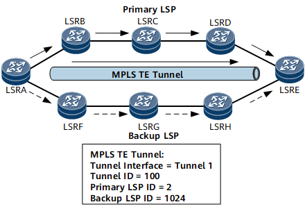
Technology Overview
Related Concepts
Concept |
Description |
|---|---|
MPLS TE tunnel |
MPLS TE often associates multiple LSPs with a virtual tunnel interface, and such a group of LSPs is called an MPLS TE tunnel. An MPLS TE tunnel is uniquely identified by the following parameters:
|
CR-LSP |
LSPs in an MPLS TE tunnel are generally called constraint-based routed label switched paths (CR-LSPs). Unlike Label Distribution Protocol (LDP) LSPs that are established based on routing information, CR-LSPs are established based on bandwidth and path constraints in addition to routing information. |
MPLS TE Tunnel Establishment and Application
An MPLS TE tunnel is established using a series of protocol components, as shown in Table 2. They work in sequence during tunnel establishment.
No. |
Name |
Description |
|---|---|---|
1 |
In addition to network topology information, TE requires network load information. MPLS TE introduces the information advertisement component by extending an existing IGP, so that TE information can be advertised. TE information includes the maximum link bandwidth, maximum reservable bandwidth, reserved bandwidth, and link colors. Each node collects TE information about all nodes in a local area and generates a traffic engineering database (TEDB). |
|
2 |
The path calculation component runs the Constraint Shortest Path First (CSPF) algorithm and uses data in the TEDB to calculate a path that satisfies specific constraints. Evolving from the Shortest Path First (SPF) algorithm, CSPF excludes nodes and links that do not satisfy specific constraints and uses SPF to calculate a path. |
|
3 |
The path establishment component establishes the following types of CR-LSPs:
|
|
4 |
The traffic forwarding component imports traffic to MPLS TE tunnels and forwards the traffic based on MPLS. The preceding three components are enough for setting up an MPLS TE tunnel. However, an MPLS TE tunnel cannot automatically import traffic after being set up. Instead, it requires the traffic forwarding component to import traffic to the tunnel. |
An MPLS TE network administrator only needs to configure link attributes based on link resource status and tunnel attributes based on service needs and network planning. MPLS TE can then automatically establish tunnels based on the configurations. After tunnels are set up and traffic import is configured, traffic can then be forwarded along tunnels.
