Example for Configuring a Tunnel Selector in an Inter-AS VPN Option B Scenario with MPLS TE Tunnels
After a tunnel selector is used in an inter-AS VPN Option B scenario, VPN data can be carried by MPLS TE tunnels, guaranteeing bandwidth for traffic transmission.
Networking Requirements
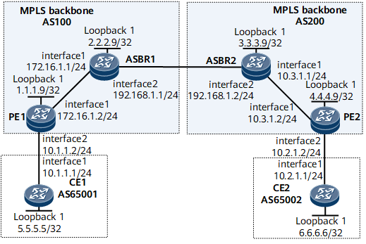
On the network shown in Figure 1, CE1 and CE2 belong to the same VPN. PE1 and PE2 belong to different ASs. Therefore, the carrier uses the inter-AS VPN Option B mode to enable different ASs to communicate. By default, the system selects only LDP LSPs for VPN data transmission. A lot of real-time services such as voice and online video services are transmitted between VPNs. To guarantee bandwidth and security for these services, the carrier wants to have all the services transmitted over MPLS TE tunnels. A tunnel selector must be applied on the ASBRs so that the ASBRs can recurse VPNv4 routes to MPLS TE tunnels.

Configuration Roadmap
The configuration roadmap is as follows:
Configure an IGP on the MPLS backbone network for the ASBR and PE in the same AS to communicate.
Enable MPLS and MPLS TE on the ASBRs and PEs and establish an MPLS TE tunnel between the ASBR and PE in the same AS.
Establish an MP-IBGP peer relationship between the ASBR and PE in the same AS.
Configure a VPN instance on each PE and establish an EBGP peer relationship between each PE and its directly connected CE.
Establish an MP-EBGP peer relationship between the ASBRs.
Configure a tunnel policy and a tunnel selector. Apply the tunnel policy to the VPN instance of each PE and the tunnel selector to the BGP-VPNv4 address family of each ASBR.
Data Preparation
To complete the configuration, you need the following data:
MPLS LSR IDs of PE1 (1.1.1.9), ASBR1 (2.2.2.9), ASBR2 (3.3.3.9), and PE2 (4.4.4.9)
Name (vpn1), RD (100:1), and export and import VPN targets (1:1) of the VPN instance on each PE
Tunnel policy name (bindTE) and tunnel selector name (bindTE)
Procedure
- Configure the inter-AS VPN Option B mode and establish MPLS TE tunnels on the BGP/MPLS backbone network.
- Configure an IP address for each interface on each CE, PE, and ASBR, as shown in Figure 1.
- Configure an IGP (OSPF in this example) on the MPLS backbone network. When configuring OSPF, advertise the 32-bit addresses of loopback interfaces on the PEs as LSR IDs.
- Establish an MPLS TE tunnel between the ASBR and PE in the same AS.
- Establish an MP-IBGP peer relationship between the ASBR and PE in the same AS and an MP-EBGP peer relationship between the ASBRs.
- Configure a VPN instance on each PE and establish an EBGP peer relationship between each PE and its directly connected CE.
For configuration details, see Example for Configuring Inter-AS VPN Option B with Basic Networking or "Configuration Files" in this section.
- Configure a tunnel policy and a tunnel selector. Apply the tunnel policy to the VPN instance of each PE and the tunnel selector to the BGP-VPNv4 address family of each ASBR.
# Configure PE1.
[PE1] interface Tunnel 10
[PE1-Tunnel10] mpls te reserved-for-binding
[PE1-Tunnel10] quit
[PE1] tunnel-policy bindTE
[PE1-tunnel-policy-bindTE] tunnel binding destination 2.2.2.9 te Tunnel10 down-switch
[PE1-tunnel-policy-bindTE] quit
[PE1] ip vpn-instance vpn1
[PE1-vpn-instance-vpn1] tnl-policy bindTE
[PE1-vpn-instance-vpn1] quit
[PE1] commit
Repeat this step for PE2. For configuration details, see Configuration Files in this section.
# Configure a tunnel policy on ASBR1.
[ASBR1] tunnel-policy bindTE
[ASBR1-tunnel-policy-bindTE] tunnel binding destination 1.1.1.9 te Tunnel10 down-switch
[ASBR1-tunnel-policy-bindTE] quit
[ASBR1] commit
# Configure a tunnel selector and apply it to the BGP-VPNv4 address family of ASBR1 so that VPNv4 routes can recurse to MPLS TE tunnels based on the tunnel policy.
[ASBR1] tunnel-selector bindTE permit node 10
[ASBR1-tunnel-selector] apply tunnel-policy bindTE
[ASBR1-tunnel-selector] quit
[ASBR1] bgp 100
[ASBR1-bgp] ipv4-family vpnv4
[ASBR1-bgp-af-vpnv4] tunnel-selector bindTE
[ASBR1-bgp-af-vpnv4] quit
[ASBR1-bgp] quit
[ASBR1] commit
The configuration of ASBR2 is similar to the configuration of ASBR1. For configuration details, see Configuration Files in this section.
After completing the configurations, run the display tunnel-policy and display tunnel-selector commands to check the configured tunnel policy or tunnel selector. The following example uses the command output on ASBR1.
<ASBR1> display tunnel-policy Total tunnel policy num: 1 Sel-Seq tunnel policy num: 0 Binding tunnel policy num: 1 Invalid tunnel policy num: 0 Tunnel Policy Name Destination Tunnel Intf Ignore-dest-check Down switch ------------------------------------------------------------------------------------------------------------------------------- bindTE 1.1.1.9 Tunnel10 Disable Enable <ASBR1> display tunnel-selector Tunnel-selector : bindTE permit : 10 Apply clauses: apply tunnel-policy bindTE - Verify the configuration.
CE1 and CE2 can ping each other successfully. The following example uses the command output on CE1.
[CE1] ping 10.2.1.1
  PING 6.6.6.6: 56  data bytes, press CTRL_C to break
    Reply from 6.6.6.6: bytes=56 Sequence=1 ttl=251 time=3 ms
    Reply from 6.6.6.6: bytes=56 Sequence=2 ttl=251 time=2 ms
    Reply from 6.6.6.6: bytes=56 Sequence=3 ttl=251 time=2 ms
    Reply from 6.6.6.6: bytes=56 Sequence=4 ttl=251 time=2 ms
    Reply from 6.6.6.6: bytes=56 Sequence=5 ttl=251 time=2 ms

  --- 6.6.6.6 ping statistics ---
    5 packet(s) transmitted
    5 packet(s) received
    0.00% packet loss
    round-trip min/avg/max = 2/2/3 ms
Run the display bgp vpnv4 all routing-table ip-address command on each ASBR. The command output shows information about the VPNv4 route to the address specified by ip-address, including information about the tunnel to which the route recurses. The following example uses network segment 5.5.5.5/32.
<ASBR1> display bgp vpnv4 all routing-table 5.5.5.5

 BGP local router ID : 172.16.1.1
 Local AS number : 100

 Total routes of Route Distinguisher(100:1): 1
 BGP routing table entry information of 5.5.5.5/32:
 Label information (Received/Applied): 16/16
 From: 1.1.1.9 (10.1.1.2)
 Route Duration: 0d01h10m10s
 Relay IP Nexthop: 172.16.1.2
 Relay IP Out-interface: GigabitEthernet0/1/0
 Relay Tunnel Out-Interface: GigabitEthernet0/1/0
 Original nexthop: 1.1.1.9
 Qos information : 0x0
 Ext-Community: RT <1 : 1>
 AS-path 65001, origin igp, MED 0, localpref 100, pref-val 0, valid, internal, b
est, select, pre 255
 Advertised to such 1 peers:
    192.168.1.2
The command output shows that the route to 5.5.5.5/32 recurses to the tunnel with the outbound interface of Tunnel 10. To check detailed information about the tunnel, run the display tunnel-info command.
<ASBR1> display tunnel-info all
Tunnel ID                     Type                Destination         Status
-----------------------------------------------------------------------------
0x000000000300000002          te                  1.1.1.9             UP
0x000000000c00000001          mpls local ifnet    192.168.1.2         UP
In summary, after the tunnel policy and tunnel selector are used in the inter-AS VPN Option B scenario, VPN data can be transmitted over the MPLS TE tunnels between the PEs and ASBRs.
Configuration Files
Configuration file of CE1
#
sysname CE1
#
interface GigabitEthernet0/1/0
 undo shutdown
 ip address 10.1.1.1 255.255.255.0
#
interface LoopBack1
 ip address 5.5.5.5 255.255.255.255
#
bgp 65001
 peer 10.1.1.2 as-number 100
 #
 ipv4-family unicast
  undo synchronization
  network 5.5.5.5 255.255.255.255
  peer 10.1.1.2 enable
#
return
Configuration file of PE1
#
sysname PE1
#
ip vpn-instance vpn1
 ipv4-family
  route-distinguisher 100:1
  apply-label per-instance
  tnl-policy bindTE
  vpn-target 1:1 import-extcommunity
  vpn-target 1:1 export-extcommunity
#
mpls lsr-id 1.1.1.9
#
mpls
 mpls te
 mpls rsvp-te
 mpls te cspf
#
interface GigabitEthernet0/1/0
 undo shutdown
 ip address 172.16.1.2 255.255.255.0
 mpls
 mpls te
 mpls te bandwidth max-reservable-bandwidth 20000
 mpls te bandwidth bc0 15000
 mpls rsvp-te
#
interface GigabitEthernet0/1/8
 undo shutdown
 ip binding vpn-instance vpn1
 ip address 10.1.1.2 255.255.255.0
#
interface LoopBack1
 ip address 1.1.1.9 255.255.255.0
#
interface Tunnel10
 ip address unnumbered interface LoopBack1
 tunnel-protocol mpls te
 destination 2.2.2.9
 mpls te tunnel-id 100
 mpls te bandwidth ct0 5000
 mpls te reserved-for-binding
#
bgp 100
 peer 2.2.2.9 as-number 100
 peer 2.2.2.9 connect-interface LoopBack1
 #
 ipv4-family unicast
  undo synchronization
  peer 2.2.2.9 enable
 #
 ipv4-family vpnv4
  policy vpn-target
  peer 2.2.2.9 enable
 #
 ipv4-family vpn-instance vpn1
  import-route direct
  peer 10.1.1.1 as-number 65001
#
ospf 1
 opaque-capability enable
 area 0.0.0.0
  mpls-te enable
  network 1.1.1.9 0.0.0.0
  network 172.16.1.0 0.0.0.255
#
tunnel-policy bindTE
 tunnel binding destination 2.2.2.9 te Tunnel10 down-switch
#
return
Configuration file of ASBR1
#
sysname ASBR1
#
tunnel-selector bindTE permit node 10
 apply tunnel-policy bindTE
#
mpls lsr-id 2.2.2.9
#
mpls
 mpls te
 mpls rsvp-te
 mpls te cspf
#
interface GigabitEthernet0/1/0
 undo shutdown
 ip address 172.16.1.1 255.255.255.0
 mpls
 mpls te
 mpls te bandwidth max-reservable-bandwidth 20000
 mpls te bandwidth bc0 15000
 mpls rsvp-te
#
interface GigabitEthernet0/1/8
 undo shutdown
 ip address 192.168.1.1 255.255.255.0
#
interface LoopBack1
 ip address 2.2.2.9 255.255.255.255
#
interface Tunnel10
 ip address unnumbered interface LoopBack1
 tunnel-protocol mpls te
 destination 1.1.1.9
 mpls te tunnel-id 200
 mpls te bandwidth ct0 5000
 mpls te reserved-for-binding
#
bgp 100
 peer 1.1.1.9 as-number 100
 peer 1.1.1.9 connect-interface LoopBack1
 peer 192.168.1.2 as-number 200
 #
 ipv4-family unicast
  undo synchronization
  peer 1.1.1.9 enable
  peer 192.168.1.2 enable
 #
 ipv4-family vpnv4
  undo policy vpn-target
  tunnel-selector bindTE
  peer 1.1.1.9 enable
  peer 192.168.1.2 enable
#
ospf 1
 opaque-capability enable
 area 0.0.0.0
  mpls-te enable
  network 2.2.2.9 0.0.0.0
  network 172.16.1.0 0.0.0.255
#
tunnel-policy bindTE
 tunnel binding destination 1.1.1.9 te Tunnel10 down-switch
#
return
Configuration file of ASBR2
#
sysname ASBR2
#
tunnel-selector bindTE permit node 10
 apply tunnel-policy bindTE
#
mpls lsr-id 3.3.3.9
#
mpls
 mpls te
 mpls rsvp-te
 mpls te cspf
#
interface GigabitEthernet0/1/0
 undo shutdown
 ip address 10.3.1.1 255.255.255.0
 mpls
 mpls te
 mpls te bandwidth max-reservable-bandwidth 20000
 mpls te bandwidth bc0 15000
 mpls rsvp-te
#
interface GigabitEthernet0/1/8
 undo shutdown
 ip address 192.168.1.2 255.255.255.0
#
interface LoopBack1
 ip address 3.3.3.9 255.255.255.255
#
interface Tunnel10
 ip address unnumbered interface LoopBack1
 tunnel-protocol mpls te
 destination 4.4.4.9
 mpls te tunnel-id 300
 mpls te bandwidth ct0 5000
 mpls te reserved-for-binding
#
bgp 200
 peer 4.4.4.9 as-number 200
 peer 4.4.4.9 connect-interface LoopBack1
 peer 192.168.1.1 as-number 100
 #
 ipv4-family unicast
  undo synchronization
  peer 4.4.4.9 enable
  peer 192.168.1.1 enable
 #
 ipv4-family vpnv4
  undo policy vpn-target
  tunnel-selector bindTE
  peer 4.4.4.9 enable
  peer 192.168.1.1 enable
#
ospf 1
 opaque-capability enable
 area 0.0.0.0
  mpls-te enable
  network 3.3.3.9 0.0.0.0
  network 10.3.1.0 0.0.0.255
#
tunnel-policy bindTE
 tunnel binding destination 4.4.4.9 te Tunnel10 down-switch
#
return
Configuration file of PE2
#
sysname PE2
#
ip vpn-instance vpn1
 ipv4-family
  route-distinguisher 100:1
  apply-label per-instance
  tnl-policy bindTE
  vpn-target 1:1 import-extcommunity
  vpn-target 1:1 export-extcommunity
#
mpls lsr-id 4.4.4.9
#
mpls
 mpls te
 mpls rsvp-te
 mpls te cspf
#
interface GigabitEthernet0/1/0
 undo shutdown
 ip address 10.3.1.2 255.255.255.0
 mpls
 mpls te
 mpls te bandwidth max-reservable-bandwidth 20000
 mpls te bandwidth bc0 15000
 mpls rsvp-te
#
interface GigabitEthernet0/1/8
 undo shutdown
 ip binding vpn-instance vpn1
 ip address 10.2.1.2 255.255.255.0
#
interface LoopBack1
 ip address 4.4.4.9 255.255.255.255
#
interface Tunnel10
 ip address unnumbered interface LoopBack1
 tunnel-protocol mpls te
 destination 3.3.3.9
 mpls te tunnel-id 400
 mpls te bandwidth ct0 5000
 mpls te reserved-for-binding
#
bgp 200
 peer 3.3.3.9 as-number 200
 peer 3.3.3.9 connect-interface LoopBack1
 #
 ipv4-family unicast
  undo synchronization
  peer 3.3.3.9 enable
 #
 ipv4-family vpnv4
  policy vpn-target
  peer 3.3.3.9 enable
 #
 ipv4-family vpn-instance vpn1
  import-route direct
  peer 10.2.1.1 as-number 65002
#
ospf 1
 opaque-capability enable
 area 0.0.0.0
  mpls-te enable
  network 4.4.4.9 0.0.0.0
  network 10.3.1.0 0.0.0.255
#
tunnel-policy bindTE
 tunnel binding destination 3.3.3.9 te Tunnel10 down-switch
#
return
Configuration file of CE2
#
sysname CE2
#
interface GigabitEthernet0/1/0
 undo shutdown
 ip address 10.2.1.1 255.255.255.0
#
interface LoopBack1
 ip address 6.6.6.6 255.255.255.255
#
bgp 65002
 peer 10.2.1.2 as-number 200
 #
 ipv4-family unicast
  undo synchronization
  network 6.6.6.6 255.255.255.255
  peer 10.2.1.2 enable
#
return