Example for Configuring a Tunnel Policy for an L3VPN
To fully use tunnel resources, you can apply different tunnel policies to load balance the traffic of different VPNs among different tunnels.
Networking Requirements
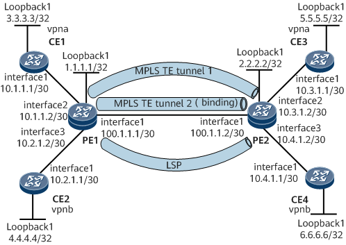
Figure 1 shows an MPLS L3VPN. CE1 and CE3 belong to vpna; CE2 and CE4 belong to vpnb. Two MPLS TE tunnels and one LSP are set up between PE1 and PE2. One of the MPLS TE tunnels is 5 Mbit/s, and the other is 10 Mbit/s. CEs in vpna require a bandwidth of 10 Mbit/s for communication. Therefore, you need to bind the eligible tunnel to vpna to ensure the bandwidth of vpna. To make full use of tunnel resources, vpnb load-balances traffic among tunnels and prefers MPLS TE tunnels.
Configuration Roadmap
The configuration roadmap is as follows:
Configure a routing protocol to ensure that PEs can communicate.
Configure MPLS both globally and per interface on each node of the backbone network and set up an LSP and two MPLS TE tunnels between PEs.
Configure VPN instances on PEs and connect CEs to PEs.
Configure tunnel policies and apply the policies to different VPN instances.
Configure the Multiprotocol Interior Border Gateway Protocol (MP-IBGP) on PEs to exchange VPN routing information.
Data Preparation
To complete the configuration, you need the following data.
MPLS label switching router (LSR) IDs of PEs
Names of VPN instances, RDs, and VPN targets
Names of the two tunnel policies
Procedure
- Configure an Interior Gateway Protocol (IGP) on the MPLS backbone network so that PEs can communicate.
# Configure PE1.
<HUAWEI> system-view
[~HUAWEI]sysname PE1
[*HUAWEI] commit
[~PE1] interface loopback 1
[*PE1-LoopBack1] ip address 1.1.1.1 32
[*PE1-LoopBack1] quit
[*PE1] interface gigabitEthernet0/1/0
[*PE1-GigabitEthernet0/1/0] ip address 2.1.1.1 30
[*PE1-GigabitEthernet0/1/0] undo shutdown
[*PE1-GigabitEthernet0/1/0] quit
[*PE1] ospf 1
[*PE1-ospf-1] area 0
[*PE1-ospf-1-area-0.0.0.0]network 2.1.1.0 0.0.0.3
[*PE1-ospf-1-area-0.0.0.0] network 1.1.1.1 0.0.0.0
[*PE1-ospf-1-area-0.0.0.0] quit
[*PE1-ospf-1] quit
[*PE1] commit
# Configure PE2.
<HUAWEI> system-view
[~HUAWEI]sysname PE2
[*HUAWEI] commit
[~PE2] interface loopback 1
[*PE2-LoopBack1] ip address 2.2.2.2 32
[*PE2-LoopBack1] quit
[*PE2] interface gigabitEthernet 0/1/0
[*PE2-GigabitEthernet0/1/0] ip address 2.1.1.2 30
[*PE2-GigabitEthernet0/1/0] undo shutdown
[*PE2-GigabitEthernet0/1/0] quit
[*PE2] ospf 1
[*PE2-ospf-1] area 0
[*PE2-ospf-1-area-0.0.0.0] network 2.1.1.0 0.0.0.3
[*PE2-ospf-1-area-0.0.0.0] network 2.2.2.2 0.0.0.0
[*PE2-ospf-1-area-0.0.0.0] commit
[~PE2-ospf-1-area-0.0.0.0] quit
[~PE2-ospf-1] quit
# After completing the configurations, run the display ip routing-table command on PEs. The command output shows that PEs learn the routes to each other's Loopback1 interface.
# The following example uses the command output on PE1.
[~PE1] display ip routing-table
<keyword conref="../commonterms/commonterms.xml#commonterms/route-flags"></keyword>
------------------------------------------------------------------------------
Routing Table: _public_
         Destinations : 9      Routes : 9
Destination/Mask    Proto  Pre  Cost       Flags  NextHop         Interface
        1.1.1.1/32  Direct 0    0              D  127.0.0.1       LoopBack1
        2.2.2.2/32 OSPF   10  1               D  2.1.1.2       GigabitEthernet0/1/0
      2.1.1.0/30  Direct 0    0              D  2.1.1.2           GigabitEthernet0/1/0
      2.1.1.2/32  Direct 0    0              D  2.1.1.1           GigabitEthernet0/1/0
      2.1.1.3/32  Direct 0    0              D  2.1.1.2           GigabitEthernet0/1/0
      127.0.0.0/8   Direct 0    0              D  127.0.0.1       InLoopBack0
      127.0.0.1/32  Direct 0    0              D  127.0.0.1       InLoopBack0
127.255.255.255/32  Direct 0    0              D  127.0.0.1       InLoopBack0
255.255.255.255/32  Direct 0    0              D  127.0.0.1       InLoopBack0
- Configure MPLS and MPLS LDP both globally and per interface on each node of the backbone network and set up an LDP LSP between PEs.
# Configure PE1.
[~PE1] mpls lsr-id 1.1.1.1
[*PE1] mpls
[*PE1-mpls] quit
[*PE1] mpls ldp
[*PE1-mpls-ldp] quit
[*PE1] interface gigabitEthernet 0/1/0
[*PE1-GigabitEthernet0/1/0] mpls
[*PE1-GigabitEthernet0/1/0] mpls ldp
[*PE1-GigabitEthernet0/1/0] commit
[*PE1-GigabitEthernet0/1/0] quit
# Configure PE2.
[*PE2] mpls lsr-id 2.2.2.2
[*PE2] mpls
[*PE2-mpls] quit
[*PE2] mpls ldp
[*PE2-mpls-ldp] quit
[*PE2] interface gigabitEthernet 0/1/0
[*PE2-GigabitEthernet0/1/0] mpls
[*PE2-GigabitEthernet0/1/0] mpls ldp
[*PE2-GigabitEthernet0/1/0] commit
[~PE2-GigabitEthernet0/1/0] quit
After completing the configurations, run the display tunnel-info all command. The command output shows that the LSP between PE1 and PE2 is set up. Run the display mpls ldp lsp command. The command output shows LSP information.
# The following example uses the command output on PE1.
[~PE1] display tunnel-info all
Tunnel ID                     Type                Destination         Status
-----------------------------------------------------------------------------
0x0000000001004c4b81          ldp                 2.2.2.2             UP
<PE1> display mpls ldp lsp
  LDP LSP Information
 -------------------------------------------------------------------------------
 DestAddress/Mask   In/OutLabel    UpstreamPeer    NextHop         OutInterface
 -------------------------------------------------------------------------------
*1.1.1.1/32         Liberal/16                     DS/2.2.2.2
 1.1.1.1/32         3/NULL         2.2.2.2         127.0.0.1       Loop1
 2.2.2.2/32         NULL/3         -               2.1.1.2         GE0/1/0
 2.2.2.2/32         16/3           2.2.2.2         2.1.1.2         GE0/1/0
 -------------------------------------------------------------------------------
 TOTAL: 3 Normal LSP(s) Found.
 TOTAL: 1 Liberal LSP(s) Found.
 TOTAL: 0 Frr LSP(s) Found.
An asterisk (*) before an LSP means the LSP is not established
 An asterisk (*) before a Label means the USCB or DSCB is stale
 An asterisk (*) before an UpstreamPeer means the session is stale
 An asterisk (*) before a DS means the session is stale
 An asterisk (*) before a NextHop means the LSP is FRR LSP
- Set up MPLS TE tunnels between PEs.
# Configure the maximum link bandwidth and reservable bandwidth for the MPLS TE tunnels.
# Configure PE1.
[~PE1] mpls
[*PE1-mpls] mpls te
[*PE1-mpls] mpls rsvp-te
[*PE1-mpls] mpls te cspf
[*PE1-mpls] quit
[*PE1] interface gigabitEthernet0/1/0
[*PE1-GigabitEthernet0/1/0] mpls te
[*PE1-GigabitEthernet0/1/0] mpls rsvp-te
[*PE1-GigabitEthernet0/1/0] mpls te bandwidth max-reservable-bandwidth 20000
[*PE1-GigabitEthernet0/1/0] mpls te bandwidth bc0 15000
[*PE1-GigabitEthernet0/1/0] commit
[~PE1-GigabitEthernet0/1/0] quit
# Configure PE2.
[~PE2] mpls
[*PE2-mpls] mpls te
[*PE2-mpls] mpls rsvp-te
[*PE2-mpls] mpls te cspf
[*PE2-mpls] quit
[*PE2] interface gigabitEthernet0/1/0
[*PE2-GigabitEthernet0/1/0] mpls te
[*PE2-GigabitEthernet0/1/0] mpls rsvp-te
[*PE2-GigabitEthernet0/1/0] mpls te bandwidth max-reservable-bandwidth 20000
[*PE2-GigabitEthernet0/1/0] mpls te bandwidth bc0 15000
[*PE2-GigabitEthernet0/1/0] commit
[~PE2-GigabitEthernet0/1/0] quit
# Enable Open Shortest Path First (OSPF) on the devices along the MPLS TE tunnels to transmit the MPLS TE attributes.
# Configure PE1.
[~PE1] ospf 1
[*PE1-ospf-1] opaque-capability enable
[*PE1-ospf-1] area 0
[*PE1-ospf-1-area-0.0.0.0] mpls-te enable
[*PE1-ospf-1-area-0.0.0.0] commit
[*PE1-ospf-1-area-0.0.0.0] quit
[~PE1-ospf-1] quit
# Configure PE2.
[~PE2] ospf 1
[*PE2-ospf-1] opaque-capability enable
[*PE2-ospf-1] area 0
[*PE2-ospf-1-area-0.0.0.0] mpls-te enable
[*PE2-ospf-1-area-0.0.0.0] commit
[*PE2-ospf-1-area-0.0.0.0] quit
[~PE2-ospf-1] quit
# Set up an MPLS TE tunnel of 5 Mbit/s.
# Configure PE1.
[~PE1] interface Tunnel 10
[*PE1-Tunnel10] ip address unnumbered interface loopback1
[*PE1-Tunnel10] tunnel-protocol mpls te
[*PE1-Tunnel10] destination 2.2.2.2
[*PE1-Tunnel10] mpls te tunnel-id 11
[*PE1-Tunnel10] mpls te bandwidth ct0 5000
[*PE1-Tunnel10] commit
[~PE1-Tunnel10] quit
# Configure PE2.
[*PE2] interface Tunnel 10
[*PE2-Tunnel10] ip address unnumbered interface loopback1
[*PE2-Tunnel10] tunnel-protocol mpls te
[*PE2-Tunnel10] destination 1.1.1.1
[*PE2-Tunnel10] mpls te tunnel-id 11
[*PE2-Tunnel10] mpls te bandwidth ct0 5000
[*PE2-Tunnel10] commit
[*PE2-Tunnel10] quit
# Set up an MPLS TE tunnel of 10 Mbit/s and bind the tunnel to a VPN instance.
# Configure PE1.
[~PE1] interface Tunnel 20
[*PE1-Tunnel20] ip address unnumbered interface loopback1
[*PE1-Tunnel20] tunnel-protocol mpls te
[*PE1-Tunnel20] destination 2.2.2.2
[*PE1-Tunnel20] mpls te tunnel-id 22
[*PE1-Tunnel20] mpls te bandwidth ct0 10000
[*PE1-Tunnel20] mpls te reserved-for-binding
[*PE1-Tunnel20] commit
[*PE1-Tunnel20] quit
# Configure PE2.
[*PE2] interface Tunnel 20
[*PE2-Tunnel20] ip address unnumbered interface loopback1
[*PE2-Tunnel20] tunnel-protocol mpls te
[*PE2-Tunnel20] destination 1.1.1.1
[*PE2-Tunnel20] mpls te tunnel-id 22
[*PE2-Tunnel20] mpls te bandwidth ct0 10000
[*PE2-Tunnel20] mpls te reserved-for-binding
[*PE2-Tunnel20] commit
[~PE2-Tunnel20] quit
# After completing the configurations, run the display tunnel-info all command on PEs. The command output shows that Tunnel10 and Tunnel20 interfaces are both Up. The following example uses the command output on PE1.
<PE1> display tunnel-info all
Tunnel ID                     Type                Destination         Status
-----------------------------------------------------------------------------
0x0000000001004c4b81          ldp                 2.2.2.2             UP
0x000000000300000001          te                  2.2.2.2             UP
0x000000000300000002          te                  2.2.2.2             UP
- Configure VPN instances on PEs and configure CEs to access PEs.
# Configure PE1.
[~PE1] ip vpn-instance vpna
[*PE1-vpn-instance-vpna] ipv4-family
[*PE1-vpn-instance-vpna-af-ipv4] route-distinguisher 100:1
[*PE1-vpn-instance-vpna-af-ipv4] vpn-target 111:1 both
[*PE1-vpn-instance-vpna-af-ipv4] quit
[*PE1-vpn-instance-vpna] quit
[*PE1] ip vpn-instance vpnb
[*PE1-vpn-instance-vpnb] ipv4-family
[*PE1-vpn-instance-vpnb-af-ipv4] route-distinguisher 100:2
[*PE1-vpn-instance-vpnb-af-ipv4] vpn-target 222:2 both
[*PE1-vpn-instance-vpnb-af-ipv4] quit
[*PE1-vpn-instance-vpnb] quit
[*PE1] interface gigabitEthernet 0/1/8
[*PE1-GigabitEthernet0/1/8] ip binding vpn-instance vpna
[*PE1-GigabitEthernet0/1/8] ip address 10.1.1.2 30
[*PE1-GigabitEthernet0/1/8] undo shutdown
[*PE1-GigabitEthernet0/1/8] quit
[*PE1] interface gigabitEthernet 0/1/16
[*PE1-GigabitEthernet0/1/16] ip binding vpn-instance vpnb
[*PE1-GigabitEthernet0/1/16] ip address 10.2.1.2 30
[*PE1-GigabitEthernet0/1/16] undo shutdown
[*PE1-GigabitEthernet0/1/16] commit
[~PE1-GigabitEthernet0/1/16] quit
# Configure PE2.
[~PE2] ip vpn-instance vpna
[*PE2-vpn-instance-vpna] ipv4-family
[*PE2-vpn-instance-vpna-af-ipv4] route-distinguisher 100:3
[*PE2-vpn-instance-vpna-af-ipv4] vpn-target 111:1 both
[*PE2-vpn-instance-vpna-af-ipv4] quit
[*PE2-vpn-instance-vpna] quit
[*PE2] ip vpn-instance vpnb
[*PE2-vpn-instance-vpnb] ipv4-family
[*PE2-vpn-instance-vpnb-af-ipv4] route-distinguisher 100:4
[*PE2-vpn-instance-vpnb-af-ipv4] vpn-target 222:2 both
[*PE2-vpn-instance-vpnb-af-ipv4] quit
[*PE2-vpn-instance-vpnb] quit
[*PE2] interface gigabitEthernet0/1/8
[*PE2-GigabitEthernet0/1/8] ip binding vpn-instance vpna
[*PE2-GigabitEthernet0/1/8] ip address 10.3.1.2 30
[*PE2-GigabitEthernet0/1/8] undo shutdown
[*PE2-GigabitEthernet0/1/8] quit
[*PE2] interface gigabitEthernet0/1/16
[*PE2-GigabitEthernet0/1/16] ip binding vpn-instance vpnb
[*PE2-GigabitEthernet0/1/16] ip address 10.4.1.2 30
[*PE2-GigabitEthernet0/1/16] undo shutdown
[*PE2-GigabitEthernet0/1/16] commit
[~PE2-GigabitEthernet0/1/16] quit
# Assign an IP address to each interface on CEs according to Figure 1. The detailed configuration procedure is not mentioned here.
# After completing the configurations, run the display ip vpn-instance verbose command on PEs to check the configurations of VPN instances.

If a PE has multiple interfaces bound to the same VPN, when you run the ping command to ping the CE that is attached to the peer PE, you need to specify the source IP address. In other words, you need to specify -a source-ip-address in the ping -a source-ip-address -vpn-instance vpn-instance-name destination-address command. Otherwise, the ping fails.
- Create tunnel policies on PEs and apply the tunnel policies.
# Configure a tunnel binding policy and apply the policy to vpna.
# Configure PE1.
[~PE1] tunnel-policy policy1
[*PE1-tunnel-policy-policy1] tunnel binding destination 2.2.2.2 te Tunnel 20
[*PE1-tunnel-policy-policy1] quit
[*PE1] ip vpn-instance vpna
[*PE1-vpn-instance-vpna] ipv4-family
[*PE1-vpn-instance-vpna-af-ipv4] tnl-policy policy1
[*PE1-vpn-instance-vpna-af-ipv4] quit
[*PE1-vpn-instance-vpna] quit
[*PE1] commit
# Configure PE2.
[~PE2] tunnel-policy policy1
[*PE2-tunnel-policy-policy1] tunnel binding destination 1.1.1.1 te Tunnel 20
[*PE2-tunnel-policy-policy1] quit
[*PE2] ip vpn-instance vpna
[*PE2-vpn-instance-vpna] ipv4-family
[*PE2-vpn-instance-vpna-af-ipv4] tnl-policy policy1
[*PE2-vpn-instance-vpna-af-ipv4] quit
[*PE2-vpn-instance-vpna] quit
[*PE2] commit
# Configure a tunnel type prioritizing policy and apply the policy to vpnb.
# Configure PE1.
[~PE1] tunnel-policy policy2
[*PE1-tunnel-policy-policy2] tunnel select-seq cr-lsp lsp load-balance-number 2
[*PE1-tunnel-policy-policy2] quit
[*PE1] ip vpn-instance vpnb
[*PE1-vpn-instance-vpnb] ipv4-family
[*PE1-vpn-instance-vpnb-af-ipv4] tnl-policy policy2
[*PE1-vpn-instance-vpnb-af-ipv4] quit
[*PE1-vpn-instance-vpnb] quit
[*PE1] commit
# Configure PE2.
[~PE2] tunnel-policy policy2
[*PE2-tunnel-policy-policy2] tunnel select-seq cr-lsp lsp load-balance-number 2
[*PE2-tunnel-policy-policy2] quit
[*PE2] ip vpn-instance vpnb
[*PE2-vpn-instance-vpnb] ipv4-family
[*PE2-vpn-instance-vpnb-af-ipv4] tnl-policy policy2
[*PE2-vpn-instance-vpnb-af-ipv4] quit
[*PE2-vpn-instance-vpnb] quit
[*PE2] commit
- Set up an MP-IBGP peer relationship between PEs.
# Configure PE1.
[~PE1] bgp 100
[*PE1-bgp] peer 2.2.2.2 as-number 100
[*PE1-bgp] peer 2.2.2.2 connect-interface loopback 1
[*PE1-bgp] ipv4-family vpnv4
[*PE1-bgp-af-vpnv4] peer 2.2.2.2 enable
[*PE1-bgp-af-vpnv4] commit
[~PE1-bgp-af-vpnv4] quit
# Configure PE2.
[~PE2] bgp 100
[*PE2-bgp] peer 1.1.1.1 as-number 100
[*PE2-bgp] peer 1.1.1.1 connect-interface loopback 1
[*PE2-bgp] ipv4-family vpnv4
[*PE2-bgp-af-vpnv4] peer 1.1.1.1 enable
[*PE2-bgp-af-vpnv4] commit
[~PE2-bgp-af-vpnv4] quit
# After completing the configurations, run the display bgp peer or display bgp vpnv4 all peer command on PEs. The command output shows that a BGP peer relationship is set up between PEs and the BGP peer relationship is in the Established state.
- Set up External Border Gateway Protocol (EBGP) peer relationships between PEs and CEs.
# Configure PE1.
[~PE1] bgp 100
[*PE1-bgp] ipv4-family vpn-instance vpna
[*PE1-bgp-af-vpna] peer 10.1.1.1 as-number 65410
[*PE1-bgp-af-vpna] quit
[*PE1-bgp] ipv4-family vpn-instance vpnb
[*PE1-bgp-af-vpnb] peer 10.2.1.1 as-number 65410
[*PE1-bgp-af-vpnb] commit
[~PE1-bgp-af-vpnb] quit
[~PE1-bgp] quit
# Configure CE1.
[~CE1] bgp 65410
[*CE1-bgp] peer 10.1.1.2 as-number 100
[*CE1-bgp] import-route direct
[*CE1-bgp] commit
[~CE1-bgp] quit
# Configure CE2.
~[CE2] bgp 65410
[*CE2-bgp] peer 10.2.1.2 as-number 100
[*CE2-bgp] import-route direct
[*CE2-bgp] commit
[~CE2-bgp] quit
# Configure PE2.
[~PE2] bgp 100
[*PE2-bgp] ipv4-family vpn-instance vpna
[*PE2-bgp-af-vpna] peer 10.3.1.1 as-number 65420
[*PE2-bgp-af-vpna] quit
[*PE2-bgp] ipv4-family vpn-instance vpnb
[*PE2-bgp-af-vpnb] peer 10.4.1.1 as-number 65420
[*PE2-bgp-af-vpnb] commit
[~PE2-bgp-af-vpnb] quit
[~PE2-bgp] quit
# Configure CE3.
[~CE3] bgp 65420
[*CE3-bgp] peer 10.3.1.2 as-number 100
[*CE3-bgp] import-route direct
[*CE3-bgp] commit
[~CE3-bgp] quit
# Configure CE4.
[~CE4] bgp 65420
[*CE4-bgp] peer 10.4.1.2 as-number 100
[*CE4-bgp] import-route direct
[*CE4-bgp] commit
[~CE4-bgp] quit
- Verify the configuration.
# Run the display bgp routing-table command on CEs. The command output shows the routes to remote CEs.
# The following example uses the command output on CE1.
<CE1> display bgp routing-table

 BGP Local router ID is 3.3.3.3
 Status codes: * - valid, > - best, d - damped, x - best external, a - add path,
               h - history,  i - internal, s - suppressed, S - Stale
               Origin : i - IGP, e - EGP, ? - incomplete

 Total Number of Routes: 5
      Network            NextHop        MED        LocPrf    PrefVal Path/Ogn

 *>   3.3.3.3/32         0.0.0.0         0                     0      ?
 *>   5.5.5.5/32       10.1.1.2                              0      100 65420?
 *>   10.1.1.0/30        0.0.0.0         0                     0      ?
 *>   10.1.1.2/32        0.0.0.0         0                     0      ?
 *>   10.3.1.0/30        10.1.1.2                              0      100 65420?
# Run the display ip routing-table vpn-instance verbose command on PEs. The command output shows the tunnel used by VPN routing.
# The following example uses the command output on PE1.
[~PE1] display ip routing-table vpn-instance vpna 5.5.5.5 verbose
Route Flags: R - relay, D - download to fib, T - to vpn-instance, B - black hole route
------------------------------------------------------------------------------
Routing Table : vpna
Summary Count : 1
 Destination: 5.5.5.5/32
    Protocol: IBGP             Process ID: 0
  Preference: 255                    Cost: 0
     NextHop: 2.2.2.2           Neighbour: 0.0.0.0
       State: Active Adv Relied       Age: 00h00m08s
         Tag: 0                  Priority: low
       Label: 0x13                QoSInfo: 0x0
  IndirectID: 0xb9
RelayNextHop: 0.0.0.0           Interface: Tunnel20
    TunnelID: 0x000000000300000002  Flags: RD
[~PE1] display ip routing-table vpn-instance vpnb 6.6.6.6 verbose
Route Flags: R - relay, D - download to fib, T - to vpn-instance, B - black hole route
------------------------------------------------------------------------------
Routing Table : vpnb
Summary Count : 1

Destination: 6.6.6.6/32
     Protocol: IBGP            Process ID: 0
   Preference: 255                   Cost: 0
      NextHop: 2.2.2.2          Neighbour: 0.0.0.0
        State: Active Adv Relied      Age: 00h04m37s
          Tag: 0                 Priority: low
        Label: 0x15               QoSInfo: 0x0
   IndirectID: 0xb8
 RelayNextHop: 0.0.0.0          Interface: Tunnel10
     TunnelID: 0x000000000300000001 Flags: RD
 RelayNextHop: 2.1.1.2          Interface: GigabitEthernet0/1/0
     TunnelID: 0x0000000001004c4b81 Flags: RD
# CEs in the same VPN can ping through each other whereas CEs in different VPNs cannot.
For example, CE1 can ping CE3 at 10.3.1.1, but cannot ping CE4 at 10.4.1.1.[~CE1] ping -a 3.3.3.3 5.5.5.5 PING 5.5.5.5: 56 data bytes, press CTRL_C to break Reply from 5.5.5.5: bytes=56 Sequence=1 ttl=251 time=72 ms Reply from 5.5.5.5: bytes=56 Sequence=2 ttl=251 time=34 ms Reply from 5.5.5.5: bytes=56 Sequence=3 ttl=251 time=50 ms Reply from 5.5.5.5: bytes=56 Sequence=4 ttl=251 time=50 ms Reply from 5.5.5.5: bytes=56 Sequence=5 ttl=251 time=34 ms --- 5.5.5.5 ping statistics --- 5 packet(s) transmitted 5 packet(s) received 0.00% packet loss round-trip min/avg/max = 34/48/72 ms [~CE1] ping -a 3.3.3.3 6.6.6.6 PING 6.6.6.6: 56 data bytes, press CTRL_C to break Request time out Request time out Request time out Request time out Request time out --- 6.6.6.6 ping statistics --- 5 packet(s) transmitted 0 packet(s) received 100.00% packet loss
Configuration Files
Configuration file of PE1
#
sysname PE1
#
ip vpn-instance vpna
 ipv4-family
  route-distinguisher 100:1
  apply-label per-instance
  tnl-policy policy1
  vpn-target 111:1 export-extcommunity
  vpn-target 111:1 import-extcommunity
#
ip vpn-instance vpnb
 ipv4-family
  route-distinguisher 100:2
  apply-label per-instance
  tnl-policy policy2
  vpn-target 222:2 export-extcommunity
  vpn-target 222:2 import-extcommunity
#
 mpls lsr-id 1.1.1.1
#
mpls
  mpls te
  mpls rsvp-te
  mpls te cspf
#
mpls ldp
#
interface GigabitEthernet0/1/0
 undo shutdown
 ip address 2.1.1.1 255.255.255.252
 mpls
 mpls te
 mpls te bandwidth max-reservable-bandwidth 20000
 mpls te bandwidth bc0 15000
 mpls rsvp-te
 mpls ldp
#
interface GigabitEthernet0/1/8
 undo shutdown
 ip binding vpn-instance vpna
 ip address 10.1.1.2 255.255.255.252
#
interface GigabitEthernet0/1/16
 undo shutdown
 ip binding vpn-instance vpnb
 ip address 10.2.1.2 255.255.255.252
#
interface LoopBack1
 ip address 1.1.1.1 255.255.255.255
#
interface Tunnel10
 ip address unnumbered interface LoopBack1
 tunnel-protocol mpls te
 destination 2.2.2.2
 mpls te tunnel-id 11
 mpls te bandwidth ct0 5000
#
interface Tunnel20
 ip address unnumbered interface LoopBack1
 tunnel-protocol mpls te
 destination 2.2.2.2
 mpls te tunnel-id 22
 mpls te bandwidth ct0 10000
 mpls te reserved-for-binding
#
bgp 100
 peer 2.2.2.2 as-number 100
 peer 2.2.2.2 connect-interface LoopBack1
 #
 ipv4-family unicast
  undo synchronization
  peer 2.2.2.2 enable
 #
 ipv4-family vpnv4
  policy vpn-target
  peer 2.2.2.2 enable
 #
 ipv4-family vpn-instance vpna
  peer 10.1.1.1 as-number 65410
 #
 ipv4-family vpn-instance vpnb
  peer 10.2.1.1 as-number 65410
#
ospf 1
 opaque-capability enable
 area 0.0.0.0
  mpls-te enable
  network 2.1.1.0 0.0.0.3
  network 1.1.1.1 0.0.0.0
#
tunnel-policy  policy1
 tunnel binding destination 2.2.2.2 te Tunnel20
#
tunnel-policy  policy2
 tunnel select-seq cr-lsp lsp load-balance-number 2
#
return
Configuration file of PE2
#
sysname PE2
#
ip vpn-instance vpna
 ipv4-family
  route-distinguisher 100:3
  apply-label per-instance
  tnl-policy policy1
  vpn-target 111:1 export-extcommunity
  vpn-target 111:1 import-extcommunity
#
ip vpn-instance vpnb
 ipv4-family
  route-distinguisher 100:4
  apply-label per-instance
  tnl-policy policy2
  vpn-target 222:2 export-extcommunity
  vpn-target 222:2 import-extcommunity
#
 mpls lsr-id 2.2.2.2
#
mpls
  mpls te
  mpls rsvp-te
  mpls te cspf
#
mpls ldp
#
interface GigabitEthernet0/1/0
 undo shutdown
 ip address 2.1.1.2 255.255.255.252
 mpls
 mpls te
 mpls te bandwidth max-reservable-bandwidth 20000
 mpls te bandwidth bc0 15000
 mpls rsvp-te
 mpls ldp
#
interface GigabitEthernet0/1/8
 undo shutdown
 ip binding vpn-instance vpna
 ip address 10.3.1.2 255.255.255.252
#
interface GigabitEthernet0/1/16
 undo shutdown
 ip binding vpn-instance vpnb
 ip address 10.4.1.2 255.255.255.252
#
interface LoopBack1
 ip address 2.2.2.2 255.255.255.255
#
interface Tunnel10
 ip address unnumbered interface LoopBack1
 tunnel-protocol mpls te
 destination 1.1.1.1
 mpls te tunnel-id 11
 mpls te bandwidth ct0 5000
#
interface Tunnel20
 ip address unnumbered interface LoopBack1
 tunnel-protocol mpls te
 destination 1.1.1.1
 mpls te tunnel-id 22
 mpls te bandwidth ct0 10000
 mpls te reserved-for-binding
#
bgp 100
 peer 1.1.1.1 as-number 100
 peer 1.1.1.1 connect-interface LoopBack1
 #
 ipv4-family unicast
  undo synchronization
  peer 1.1.1.1 enable
 #
 ipv4-family vpnv4
  policy vpn-target
  peer 1.1.1.1 enable
 #
 ipv4-family vpn-instance vpna
  peer 10.3.1.1 as-number 65420
 #
 ipv4-family vpn-instance vpnb
  peer 10.4.1.1 as-number 65420
#
ospf 1
 opaque-capability enable
 area 0.0.0.0
  mpls-te enable
  network 2.1.1.0 0.0.0.3
  network 2.2.2.2 0.0.0.0
#
tunnel-policy  policy1
 tunnel binding destination 1.1.1.1 te Tunnel20
#
tunnel-policy  policy2
 tunnel select-seq cr-lsp lsp load-balance-number 2
#
return
Configuration file of CE1
#
sysname CE1
#
interface GigabitEthernet0/1/0
 undo shutdown
 ip address 10.1.1.1 255.255.255.252
#
interface LoopBack1
ip address 3.3.3.3 255.255.255.255
#
bgp 65410
 peer 10.1.1.2 as-number 100
 #
 ipv4-family unicast
  undo synchronization
  import-route direct
  peer 10.1.1.2 enable
#
return
Configuration file of CE2
#
sysname CE2
#
interface GigabitEthernet0/1/0
 undo shutdown
 ip address 10.2.1.1 255.255.255.252
#
interface LoopBack1
ip address 4.4.4.4 255.255.255.255
#
bgp 65410
 peer 10.2.1.2 as-number 100
 #
 ipv4-family unicast
  undo synchronization
  import-route direct
  peer 10.2.1.2 enable
#
return
Configuration file of CE3
#
sysname CE3
#
interface GigabitEthernet0/1/0
undo shutdown
ip address 10.3.1.1 255.255.255.252
#
interface LoopBack1
ip address 5.5.5.5 255.255.255.255
#
bgp 65420
 peer 10.3.1.2 as-number 100
 #
 ipv4-family unicast
  undo synchronization
  import-route direct
  peer 10.3.1.2 enable
#
return
Configuration file of CE4
#
sysname CE4
#
interface GigabitEthernet0/1/0
undo shutdown
ip address 10.4.1.1 255.255.255.252
#
interface LoopBack1
ip address 6.6.6.6 255.255.255.255
#
bgp 65420
 peer 10.4.1.2 as-number 100
 #
 ipv4-family unicast
  undo synchronization
  import-route direct
  peer 10.4.1.2 enable
#
return