VLAN Overview
The VLAN technology is important for Layer 2 network forwarding. This section describes the background, functions, and advantages of the VLAN technology.
Introduction
The network constructs a collision domain. More computers on the network cause more conflicts and lower network efficiency. The network is also a broadcast domain. When many computers on the network send data, broadcast traffic consumes much bandwidth.
Traditional networks face collision domain and broadcast domain issues, and cannot ensure information security.
To reduce the broadcast traffic, you need to enable the broadcast only among hosts that need to communicate with each other, and isolate the hosts that do not need the broadcast. A router can select routes based on IP addresses and effectively suppress broadcast traffic between two connected network segments. The router solution, however, is costly. Therefore, multiple logical LANs, namely, VLANs are developed on the physical LAN.
In this manner, a physical LAN is divided into multiple broadcast domains, that is, multiple VLANs. The intra-VLAN communication is not restricted, while the inter-VLAN communication is restricted. As a result, network security is enhanced.
Definition
The virtual local area network (VLAN) technology logically divides a physical LAN into multiple VLANs that are broadcast domains. Each VLAN contains a group of PCs that have the same requirements. A VLAN has the same attributes as a LAN. PCs of a VLAN can be placed on different LAN segments. Hosts can communicate within the same VLAN, while cannot communicate in different VLANs. If two PCs are located on one LAN segment but belong to different VLANs, they do not broadcast packets to each other. In this manner, network security is enhanced.
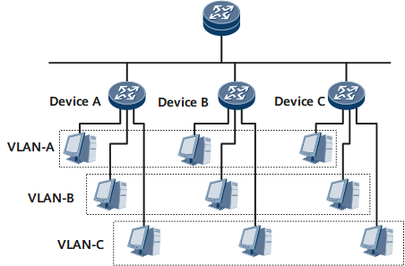
Figure 1 is a networking diagram of a typical VLAN application. Device A, Device B, and Device C are placed at different locations, such as different floors in an office building. Each switch connects to three computers which belong to three different VLANs. In Figure 1, each dashed line frame identifies a VLAN. Packets of enterprise customers in the same VLAN are broadcast within the VLAN but not among VLANs. In this way, enterprise customers in the same VLAN can share resources as well as protect their information security.
- Broadcast domains are confined. A broadcast domain is confined to a VLAN. This saves bandwidth and improves network processing capabilities.
- Network security is enhanced. Packets from different VLANs are separately transmitted. PCs in one VLAN cannot directly communicate with PCs in another VLAN.
- Network robustness is improved. A fault in a VLAN does not affect PCs in other VLANs.
- Virtual groups are set up flexibly. With the VLAN technology, PCs in different geographical areas can be grouped together. This facilitates network construction and maintenance.
Basic VLAN Concepts and Principles
802.1q and VLAN frame format
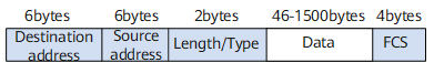
A conventional Ethernet frame is encapsulated with the Length/Type field for an upper-layer protocol following the Destination address and Source address fields, as shown in Figure 2.
IEEE 802.1Q defines a VLAN frame by adding a 4-byte 802.1Q tag between the source MAC address field and the Length/Type field in an Ethernet frame, as shown in Figure 1.
Figure 3 VLAN frame format defined in IEEE 802.1Q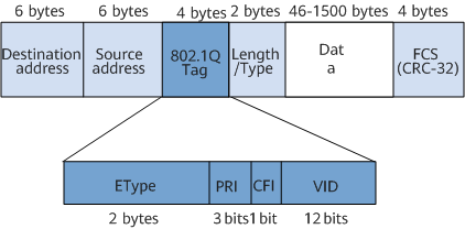
An 802.1Q tag contains four fields:
-
The 2-byte Type field indicates a frame type. If the value of the field is 0x8100, it indicates an 802.1Q frame. If a device that does not support 802.1Q frames receives an 802.1Q frame, it discards the frame.
-
The 3-bit Priority field indicates the frame priority. A greater the PRI value indicates a higher frame priority. If a switch is congested, it preferentially sends frames with a higher priority.
-
The 1-bit Canonical Format Indicator (CFI) field indicates whether a MAC address is in the canonical format. If the CFI field value is 0, the MAC address is in canonical format. If the CFI field value is 1, the MAC address is not in canonical format. This field is mainly used to differentiate among Ethernet frames, Fiber Distributed Digital Interface (FDDI) frames, and token ring frames. The CFI field value in an Ethernet frame is 0.
-
The 12-bit VLAN ID (VID) field indicates to which VLAN a frame belongs. VLAN IDs range from 0 to 4095. The values 0 and 4095 are reserved, and therefore VLAN IDs range from 1 to 4094.
Each frame sent by an 802.1q-capable switch carries a VLAN ID. On a VLAN, Ethernet frames are classified into the following types:- Tagged frames: frames with 4-byte 802.1q tags.
- Untagged frames: frames without 4-byte 802.1q tags.
-
Port-based VLAN classification
VLANs are classified based on port numbers. In this mode, VLANs are classified based on the numbers of ports on a switching device. The network administrator configures a port default VLAN ID (PVID) for each port on the switch. When a data frame reaches a port which is configured with a PVID, the frame is marked with the PVID if the data frame carries no VLAN tag. If the data frame carries a VLAN tag, the switching device will not add a VLAN tag to the data frame even if the port is configured with a PVID. Different types of ports process VLAN frames in different manners.
Type of VLAN links
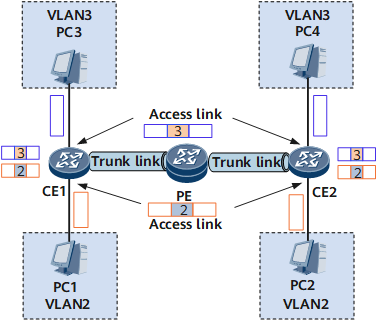
As shown in Figure 4, there are the following types of VLAN links:
Access link: a link connecting a host and a switch. Generally, a PC does not know which VLAN it belongs to, and PC hardware cannot distinguish frames with VLAN tags. Therefore, PCs send and receive only untagged frames.
Trunk link: a link connecting switches. Data of different VLANs is transmitted along a trunk link. The two ends of a trunk link must be able to distinguish frames with VLAN tags. Therefore, only tagged frames are transmitted along trunk links.
Port types
Table 1 lists VLAN port types.
Principle for data switching in a VLAN
Use the network shown in Figure 4 as an example. If PC 1 in VLAN 2 intends to send data to PC 2, the data is forwarded as follows:
An access port on CE 1 receives an untagged frame from PC 1 and adds a PVID (VLAN 2) to the frame. CE 1 searches the MAC address table for an outbound port. Then the frame is transmitted from the outbound port.
After the trunk port on PE receives the frame, the port checks whether the VLAN ID carried in the frame is the same as that configured on the port. If the VLAN ID has been configured on the port, the port transparently transmits the frame to CE 2. If the VLAN ID is not configured on the port, the port discards the frame.
After a trunk port on CE 2 receives the frame, the system searches the MAC address table for an outbound port which connects CE 2 to PC 2.
After the frame is sent to the access port connecting CE 2 to PC 2, the port checks that the VLAN ID carried in the frame is the same as that configured on the port. The port then removes the tag from the frame and sends the untagged frame to PC 2.
VLANIF interface
A VLANIF interface is a Layer 3 logical interface, which can be configured on either a Layer 3 switch or a router.
Layer 3 switching combines both routing and switching techniques to implement routing on a switch, improving the overall performance of the network. After sending the first data flow based on a routing table, a Layer 3 switch generates a mapping table, in which the mapping between the MAC address and the IP address about this data flow is recorded. If the switch needs to send the same data flow again, it directly sends the data flow at Layer 2 but not Layer 3 based on the mapping table. In this manner, delays on the network caused by route selection are eliminated, and data forwarding efficiency is improved.
To allow the first data flow to be correctly forwarded based on the routing table, the routing table must contain correct routing entries. Therefore, configuring a Layer 3 interface and a routing protocol on the Layer 3 switch is required. VLANIF interfaces are therefore introduced.

- A PC does not need to know the VLAN to which it belongs. It sends only untagged frames.
- After receiving an untagged frame from a PC, a switching device determines the VLAN to which the frame belongs. The determination is based on the configured VLAN division method such as port information, and then the switching device processes the frame accordingly.
- If the frame needs to be forwarded to another switching device, the frame must be transparently transmitted along a trunk link. Frames transmitted along trunk links must carry VLAN tags to allow other switching devices to properly forward the frame based on the VLAN information.
- Before sending the frame to the destination PC, the switching device connected to the destination PC removes the VLAN tag from the frame to ensure that the PC receives an untagged frame.
Generally, only tagged frames are transmitted on trunk links; only untagged frames are transmitted on access links. In this manner, switching devices on the network can properly process VLAN information and PCs are not concerned about VLAN information.