Configuring Sub-interfaces for Inter-VLAN Communication
If users belong to different VLANs and reside on different network segments, sub-interfaces can be created on an Layer 3 device and assigned IP addresses to allow these users to communicate with each other at the network layer.
Context
During communication at the data link layer on a LAN, source MAC addresses identify where data comes from, and destination MAC addresses guide data to destinations. If the source and destination PCs reside on different network segments, a Layer 2 network is unable to send data from the source to the destination. In this case, data has to be forwarded at the network layer 3. After the default gateway address of the Layer 2 device is specified as the IP address of the Layer 3 device, the Layer 2 device sends data that needs to be forwarded at the network layer to the Layer 3 device. After receiving a packet, the Layer 3 device searches its routing table according to the destination address in the packet. If the Layer 3 device finds a matching route in the routing table, the Layer 3 device directly forwards the packet to another network segment. If the Layer 3 device does not find any matching route, it discards the packet.
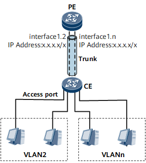
On the network shown in Figure 1, VLANs 2 to n belong to different network segments. To allow users in VLANs 2 to n to communicate with each other, you can create a sub-interface on the PE for each VLAN and assign an IP address to each sub-interface. After VLANs are configured, the CE is logically divided into n parts. Accordingly, the Layer 3 device must have n logical interfaces corresponding to n VLANs. The detailed implementation process is as follows:
- A PC in VLAN 2 checks the destination IP address and finds that the destination PC in VLAN n is on a different network segment.
- The PC in VLAN 2 sends an ARP request. After receiving the request, the PE considers itself the destination, translates its MAC address into an IP address, and sends an ARP reply to the PC in VLAN 2.
- After receiving data from the PC in VLAN 2, the CE adds a VLAN tag to the data and searches the MAC address table for an outbound port.
- The PE receives the frame and sends it to sub-interface 2.
- Sub-interface 2 removes the VLAN tag from the frame, searches for an ARP entry based on the IP address in the IP header, and forwards the packet at the network layer.
- Sub-interface n receives the packet, re-encapsulates the packet with the VLAN ID of n and the destination MAC address of the MAC address of the destination PC, and sends the frame.
- After receiving the frame, the CE searches the MAC address table for the destination MAC address based on the VLAN ID carried in the packet to determine the outbound port.
The PC in VLAN n receives the frame from VLAN 2.
If a PC in VLAN n sends a packet to a PC in VLAN 2, the process is similar and not described in this document.
On the network shown in Figure 1, downstream ports on the CE are separately added to VLAN 2 to VLAN n. The configuration roadmap for communication between these VLANs is as follows:
Create n-1 sub-interfaces on the Ethernet interface connecting the PE to the CE.
The sub-interface is associated with a VLAN.
Assign an IP address to each sub-interface for communication at the network layer.
Configure the port connecting the CE to the PE as a trunk or hybrid port to allow frames with VLAN IDs from 2 to n to pass through.

The default gateway address of each PC in a VLAN must be the IP address of the corresponding sub-interface. Otherwise, inter-VLAN communication fails.
Procedure
- Do as follows on the PE:
- Run vlan-type dot1q vlan-id
The sub-interface is associated with a VLAN.
Sub-interfaces of different interfaces can be associated with the same VLAN; sub-interfaces of one interface cannot be associated with the same VLAN.
- Run vlan-type dot1q vlan-id