Example for Configuring Inter-VLAN Communication by Using VLANIF Interfaces
In this example, Layer 3 forwarding is performed by a Layer 3 PE instead of a router. This allows PCs in different VLANs to communicate with each other and reduces operating costs.
Networking Requirements
Users in different residential compounds in different network segments require various services such as Internet, IPTV, and VoIP services. The network administrator of each residential compound configures a VLAN for each service to simplify management. After the configuration, users in different residential compounds belong to different VLANs, but they need to communicate with each other for the same type of service.
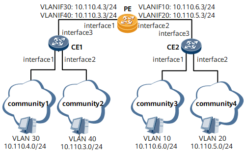
On the network shown in Figure 1, users in residential compounds 1 to 4 belong to different VLANs in different network segments but require the same online service. It is required that these users communicate with each other at a low operating cost.
Configuration Roadmap
The configuration roadmap is as follows:
- Create VLANs on CEs and determine mappings between users and VLANs.
- Configure trunk ports on CEs to allow frames with certain VLAN IDs to pass through.
- Create VLANIF interfaces on the PE and assign IP addresses to the interfaces to allow Layer 3 communication.

The default gateway address of each PC in a VLAN must be the IP address of the corresponding VLANIF interface. Otherwise, inter-VLAN communication will fail.
Data Preparation
To complete the configuration, you need the following data:
- User VLAN ID
- User IP address
- Number of each port connecting a CE to a PC
Number of the ports interconnecting CEs
Number and IP address of each VLANIF interface on the PE
Procedure
- Create VLANs on CE 1 and CE 2.
# Configure CE 1.
<HUAWEI> system-view
[~HUAWEI] sysname CE1
[*HUAWEI] commit
[~CE1] vlan batch 30 40
[*CE1] interface gigabitethernet 0/1/1
[*CE1-GigabitEthernet0/1/1] portswitch
[*CE1-GigabitEthernet0/1/1] undo shutdown
[*CE1-GigabitEthernet0/1/1] port link-type access
[*CE1-GigabitEthernet0/1/1] port default vlan 30
[*CE1-GigabitEthernet0/1/1] quit
[*CE1] interface gigabitethernet 0/1/2
[*CE1-GigabitEthernet0/1/2] portswitch
[*CE1-GigabitEthernet0/1/2] undo shutdown
[*CE1-GigabitEthernet0/1/2] port link-type access
[*CE1-GigabitEthernet0/1/2] port default vlan 40
[*CE1-GigabitEthernet0/1/2] quit
# Configure CE 2.
<HUAWEI> system-view
[~HUAWEI] sysname CE2
[*HUAWEI] commit
[~CE2] vlan batch 10 20
[*CE2] interface gigabitethernet 0/1/1
[*CE2-GigabitEthernet0/1/1] portswitch
[*CE2-GigabitEthernet0/1/1] undo shutdown
[*CE2-GigabitEthernet0/1/1] port link-type access
[*CE2-GigabitEthernet0/1/1] port default vlan 10
[*CE2-GigabitEthernet0/1/1] quit
[*CE2] interface gigabitethernet 0/1/2
[*CE2-GigabitEthernet0/1/2] portswitch
[*CE2-GigabitEthernet0/1/2] undo shutdown
[*CE2-GigabitEthernet0/1/2] port link-type access
[*CE2-GigabitEthernet0/1/2] port default vlan 20
[*CE2-GigabitEthernet0/1/2] quit
- Configure trunk ports on CE 1 and CE 2 to allow frames with certain VLAN IDs to pass through.
# Configure CE 1.
[*CE1] interface gigabitethernet 0/1/3
[*CE1-GigabitEthernet0/1/3] portswitch
[*CE1-GigabitEthernet0/1/3] undo shutdown
[*CE1-GigabitEthernet0/1/3] port link-type trunk
[*CE1-GigabitEthernet0/1/3] port trunk allow-pass vlan 30 40
[*CE1-GigabitEthernet0/1/3] quit
[*CE1] commit
# Configure CE 2.
[*CE2] interface gigabitethernet 0/1/3
[*CE2-GigabitEthernet0/1/3] portswitch
[*CE2-GigabitEthernet0/1/3] undo shutdown
[*CE2-GigabitEthernet0/1/3] port link-type trunk
[*CE2-GigabitEthernet0/1/3] port trunk allow-pass vlan 10 20
[*CE2-GigabitEthernet0/1/3] quit
[*CE2] commit
- Create VLANIF interfaces on PE and assign IP addresses to the VLANIF interfaces.
<HUAWEI> system-view
[~HUAWEI] sysname PE
[*HUAWEI] commit
[~PE] vlan batch 10 to 40
[*PE] interface gigabitethernet 0/1/1
[*PE-GigabitEthernet0/1/1] portswitch
[*PE-GigabitEthernet0/1/1] undo shutdown
[*PE-GigabitEthernet0/1/1] port link-type trunk
[*PE-GigabitEthernet0/1/1] port trunk allow-pass vlan 30 40
[*PE-GigabitEthernet0/1/1] quit
[*PE] interface gigabitethernet 0/1/2
[*PE-GigabitEthernet0/1/2] portswitch
[*PE-GigabitEthernet0/1/2] undo shutdown
[*PE-GigabitEthernet0/1/2] port link-type trunk
[*PE-GigabitEthernet0/1/2] port trunk allow-pass vlan 10 20
[*PE-GigabitEthernet0/1/2] quit
[*PE] interface Vlanif 10
[*PE-Vlanif10] ip address 10.110.6.3 24
[*PE-Vlanif10] quit
[*PE] interface Vlanif 20
[*PE-Vlanif20] ip address 10.110.5.3 24
[*PE-Vlanif20] quit
[*PE] interface Vlanif 30
[*PE-Vlanif30] ip address 10.110.4.3 24
[*PE-Vlanif30] quit
[*PE] interface Vlanif 40
[*PE-Vlanif40] ip address 10.110.3.3 24
[*PE-Vlanif40] quit
[*PE] commit
- Verify the configuration.
On PCs in VLAN 10, configure the IP address 10.110.6.3/24 of VLANIF 10 as the default gateway address.
On PCs in VLAN 20, configure the IP address 10.110.5.3/24 of VLANIF 20 as the default gateway address.
On PCs in VLAN 30, configure the IP address 10.110.4.3/24 of VLANIF 30 as the default gateway address.
On PCs in VLAN 40, configure the IP address 10.110.3.3/24 of VLANIF 40 as the default gateway address.
After the configurations, PCs in VLANs 10, 20, 30, and 40 can ping each other successfully.
Configuration Files
Configuration file of CE 1
#
 sysname CE1
#
 vlan batch 30 40
#
interface GigabitEthernet0/1/1
 portswitch
 undo shutdown
 port link-type access
 port default vlan 30
#
interface GigabitEthernet0/1/2
 portswitch
 undo shutdown
 port link-type access
 port default vlan 40
#
interface GigabitEthernet0/1/3
 portswitch
 undo shutdown
 port link-type trunk
 port trunk allow-pass vlan 30 40
#
return
Configuration file of CE 2
#
 sysname CE2
#
 vlan batch 10 20
#
interface GigabitEthernet0/1/1
 portswitch
 undo shutdown
 port link-type access
 port default vlan 10
#
interface GigabitEthernet0/1/2
 portswitch
 undo shutdown
 port link-type access
 port default vlan 20
#
interface GigabitEthernet0/1/3
 portswitch
 undo shutdown
 port link-type trunk
 port trunk allow-pass vlan 10 20
#
return
Configuration file of PE
#
 sysname PE
#
vlan batch 10 to 40
#
interface Vlanif10
 ip address 10.110.6.3 255.255.255.0
#
interface Vlanif20
 ip address 10.110.5.3 255.255.255.0
#
interface Vlanif30
 ip address 10.110.4.3 255.255.255.0
#
interface Vlanif40
 ip address 10.110.3.3 255.255.255.0
#
interface GigabitEthernet0/1/1
 portswitch
 undo shutdown
 port link-type trunk
 port trunk allow-pass vlan 30 40
#
interface GigabitEthernet0/1/2
 portswitch
 undo shutdown
 port link-type trunk
 port trunk allow-pass vlan 10 20
#
return