Example for Configuring VLAN and Non-VLAN Users to Communicate by Using Sub-interfaces
This example describes how to configure communication between VLAN users and non-VLAN users.
Networking Requirements
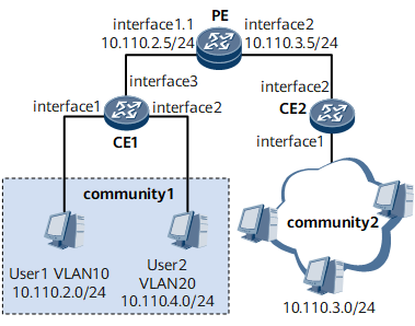
Residents in a residential compound belong to different network segments. To simplify management, the network administrator of the residential compound adds users to different VLANs. Residents in another residential compound are not added to any VLAN. VLAN users must be able to communicate with non-VLAN users.
On the network shown in Figure 1, users in residential compound 1 belong to different VLANs and reside on different network segments; users in residential compound 2 do not belong to any VLAN. It is required that users in VLAN 10 be able to communicate with users in residential compound 2.
Configuration Roadmap
The configuration roadmap is as follows:
- Create VLANs on switches and determine mappings between users and VLANs.
- Configure the trunk port on CE 1 to allow frames with certain VLAN IDs to pass through.
- Create a sub-interface on the interface connecting the router to VLAN users and associate the sub-interface with VLAN 10.
Assign IP addresses to interfaces for communication at the network layer.
- Assign an IP address to the sub-interface.
- Assign an IP address to the interface connecting the router to non-VLAN users.

- The IP address assigned to the sub-interface connected to VLAN users must be on the same network segment with IP addresses of VLAN users.
- The IP address assigned to the interface connected to non-VLAN users must be on the same network segment with IP addresses of non-VLAN users.
- The default gateway addresses of PCs in VLAN 10 must be the IP address of the sub-interface. Otherwise, VLAN and non-VLAN users cannot communicate with each other.
Data Preparation
- User VLAN ID
- User IP address
- Number of each port connecting a CE to a PC
- Number of each port connecting a CE to the PE
- Number and IP address of each sub-interface on PE
Procedure
- Create a VLAN on CE 1.
<HUAWEI> system-view
[~HUAWEI] sysname CE1
[*HUAWEI] commit
[~CE1] vlan batch 10
[*CE1-vlan10] quit
[*CE1] interface gigabitethernet 0/1/1
[*CE1-GigabitEthernet0/1/1] portswitch
[*CE1-GigabitEthernet0/1/1] undo shutdown
[*CE1-GigabitEthernet0/1/1] port link-type access
[*CE1-GigabitEthernet0/1/1] port default vlan 10
[*CE1-GigabitEthernet0/1/1] quit
- Configure the trunk port on CE 1 to allow frames with certain VLAN IDs to pass through.
[*CE1] interface gigabitethernet 0/1/3
[*CE1-GigabitEthernet0/1/3] portswitch
[*CE1-GigabitEthernet0/1/3] undo shutdown
[*CE1-GigabitEthernet0/1/3] port link-type trunk
[*CE1-GigabitEthernet0/1/3] port trunk allow-pass vlan 10 20
[*CE1-GigabitEthernet0/1/3] quit
[*CE1] commit
- Create a sub-interface on PE and associate the sub-interface with VLAN 10.
<HUAWEI> system-view
[~HUAWEI] sysname PE
[*HUAWEI] commit
[~PE] interface gigabitethernet 0/1/1
[*PE-GigabitEthernet0/1/1] undo shutdown
[*PE-GigabitEthernet0/1/1] quit
[*PE] interface gigabitethernet 0/1/1.1
[*PE-GigabitEthernet0/1/1.1] vlan-type dot1q 10
- Configure IP addresses.
[*PE-GigabitEthernet0/1/1.1] ip address 10.110.2.5 24
[*PE-GigabitEthernet0/1/1.1] quit
[*PE] interface gigabitethernet 0/1/2
[*PE-GigabitEthernet0/1/2] undo shutdown
[*PE-GigabitEthernet0/1/2] ip address 10.110.3.5 24
[*PE-GigabitEthernet0/1/2] quit
[*PE] commit
- Verify the configuration.
On PCs in VLAN 10, configure the IP address 10.110.2.5/24 of GE 0/1/1.1 as the default gateway address.
On CE 2, configure the IP address 10.110.3.5 of GE 0/1/2 as the default gateway address.
After the configurations, users in VLAN 10 and non-VLAN users can ping each other successfully.
Configuration Files
Configuration file of CE 1
#
 sysname CE1
#
 vlan batch 10
#
interface GigabitEthernet0/1/1
 portswitch
 undo shutdown
 port link-type access
 port default vlan 10
#
interface GigabitEthernet0/1/3
 portswitch
 undo shutdown
 port link-type trunk
 port trunk allow-pass vlan 10
#
return
Configuration file of PE
#
 sysname PE
#
interface GigabitEthernet0/1/1
 undo shutdown
#
interface GigabitEthernet0/1/1.1
 vlan-type dot1q 10
 ip address 10.110.2.5 255.255.255.0
#
interface GigabitEthernet0/1/2
 undo shutdown
 ip address 10.110.3.5 255.255.255.0
#
return