Configuring VLAN Mapping for Inter-VLAN Communication
The configuration of VLAN mapping is simple and independent of Layer 3 routing.
Context
Before sending a frame to VLAN 3, interface1 on CE 1 replaces the VLAN ID 2 in the frame with the VLAN ID 3.
After receiving a frame from VLAN 3, interface1 on CE 1 replaces the VLAN ID 3 in the frame with the VLAN ID 2.
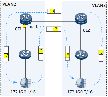

Before configuring VLAN mapping to allow PCs in two VLANs to communicate, IP addresses of the PCs must belong to the same network segment. Otherwise, devices in different VLANs must communicate with each other at the network layer. In this case, VLAN mapping does not make sense.
1 to 1 VLAN mapping
After receiving a single-tagged frame, the device replaces the tag with a specified tag.
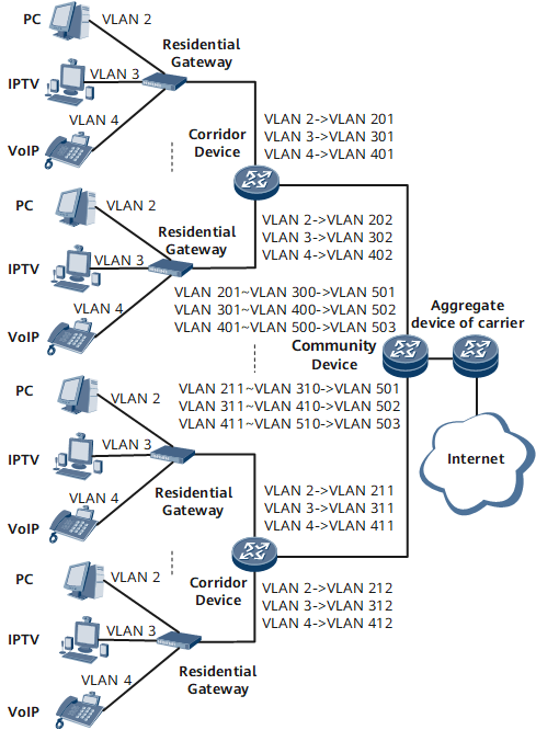
1 to 1 VLAN mapping is applicable to the networking environment shown in Figure 2.
On the network shown in Figure 2, different types of services (Internet, IPTV, and VoIP) of each household are transmitted in separate VLANs. To differentiate between households, you need to configure 1 to 1 VLAN mapping on each corridor switch to transmit the same type of services for different households in separate VLANs. In this case, the aggregate switch must provide a large number of VLAN IDs to separate services of different households. As the number of available VLAN IDs on the aggregate switch is limited, you need to implement VLAN aggregation to transmit the same type of services for different households in one VLAN.
Procedure
- Run system-view
The system view is displayed.
- Add ports connecting CE 1 and CE 2 to users to separate VLANs.
- Configure the Layer 2 port type.
Run interface interface-type interface-number
The view of an Ethernet port to be configured with VLAN mapping is displayed.
Run port link-type trunk
The Layer 2 Ethernet port is configured as a trunk port.
- Run port vlan-mapping vlan vlan-id1 [ to vlan-id2 ] map-vlan vlan-id3
VLAN mapping is configured to change the outer VLAN tag to vlan-id3.
- Run port trunk allow-pass vlan { { vlan-id1 [ to vlan-id2 ] } &<1-10> | all }
The VLAN IDs are specified. Frames carrying these VLAN IDs can pass through the port configured with VLAN mapping.
The VLAN ID specified in this command must be private VLAN IDs but not public VLAN IDs.
- Run commit
The configuration is committed.