Example for Configuring LDP VPLS
If PEs support the usage of LDP as the VPLS signaling protocol, you can configure LDP VPLS. To fully mesh PEs on a VPLS network using PWs, set up LDP sessions between all the PEs.
Networking Requirements
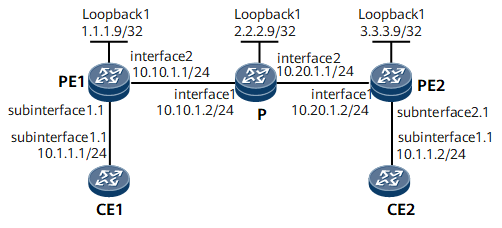
On the network shown in Figure 1, VPLS is enabled on PE1 and PE2; CE1 connects to PE1; CE2 connects to PE2; CE1 and CE2 are on the same VPLS network. PWs are established using LDP as the VPLS signaling protocol, and VPLS is configured to achieve connectivity between CE1 and CE2.

Configuration Notes
When configuring LDP VPLS, note that PEs on the same L2VPN must be configured with the same VSI ID.
Configuration Roadmap
The configuration roadmap is as follows:
Configure a routing protocol on the backbone network to achieve connectivity between devices.
Set up remote LDP sessions between PEs.
Establish tunnels between PEs for transmitting user data.
Enable MPLS L2VPN on PEs.
Create VSIs on PEs, set the signaling protocol to LDP, and bind VSIs to AC interfaces.
Data Preparation
To complete the configuration, you need the following data:
Names and IDs of VSIs
IP addresses of peers and tunnel policies used for setting up peer relationships
Names of interfaces to which VSIs are bound
Procedure
- Assign IP addresses to PEs and the Ps as described in Figure 1, and configure an IGP. This example uses OSPF as the IGP.
Note that when configuring OSPF, you need to advertise 32-bit loopback interface addresses (LSR IDs) of PE1, the P, and PE2.
For configuration details, see Configuration Files in this section.
After completing the configurations, run the display ip routing-table command on PE1, the P, and PE2. The command output shows that PE1, the P, and PE2 have learned the route to each other.
- Configure MPLS and MPLS LDP.
For configuration details, see Configuration Files in this section.
After completing the configurations, run the display mpls ldp session command on PE1, the P, and PE2. The command output shows that the status of the peer relationship between PE1 and the P, or between PE2 and the P is Operational. Run the display mpls lsp command. The command output shows whether the LSP is set up.
- Establish remote LDP sessions between PEs.
# Configure PE1.
[~PE1] mpls ldp remote-peer 3.3.3.9
[*PE1-mpls-ldp-remote-3.3.3.9] remote-ip 3.3.3.9
[*PE1-mpls-ldp-remote-3.3.3.9] quit
[*PE1] commit
# Configure PE2.
[*PE2] mpls ldp remote-peer 1.1.1.9
[*PE2-mpls-ldp-remote-1.1.1.9] remote-ip 1.1.1.9
[*PE2-mpls-ldp-remote-1.1.1.9] quit
[*PE2] commit
After completing the configurations, run the display mpls ldp session command on PE1 or PE2. The command output shows that the status of the peer relationship between PE1 and PE2 is Operational.
- Enable MPLS L2VPN on PEs.
# Configure PE1.
[~PE1] mpls l2vpn
[*PE1-l2vpn] commit
# Configure PE2.
[*PE2] mpls l2vpn
[*PE2-l2vpn] commit
- Configure VSIs on PEs.
# Configure PE1.
[~PE1] vsi a2
[*PE1-vsi-a2] pwsignal ldp
[*PE1-vsi-a2-ldp] vsi-id 2
[*PE1-vsi-a2-ldp] peer 3.3.3.9
[*PE1-vsi-a2-ldp] quit
[*PE1-vsi-a2] quit
[*PE1] commit
# Configure PE2.
[~PE2] vsi a2
[*PE2-vsi-a2] pwsignal ldp
[*PE2-vsi-a2-ldp] vsi-id 2
[*PE2-vsi-a2-ldp] peer 1.1.1.9
[*PE2-vsi-a2-ldp] quit
[*PE2-vsi-a2] quit
[*PE2] commit
- Bind VSIs to AC interfaces on PEs.
# Configure PE1.
[~PE1] interface gigabitethernet0/1/0.1
[*PE1-GigabitEthernet0/1/0.1] shutdown
[*PE1-GigabitEthernet0/1/0.1] vlan-type dot1q 10
[*PE1-GigabitEthernet0/1/0.1] l2 binding vsi a2
[*PE1-GigabitEthernet0/1/0.1] undo shutdown
[*PE1-GigabitEthernet0/1/0.1] quit
[*PE1] commit
# Configure PE2.
[~PE2] interface gigabitethernet0/1/8.1
[*PE2-GigabitEthernet0/1/8.1] shutdown
[*PE2-GigabitEthernet0/1/8.1] vlan-type dot1q 10
[*PE2-GigabitEthernet0/1/8.1] l2 binding vsi a2
[*PE2-GigabitEthernet0/1/8.1] undo shutdown
[*PE2-GigabitEthernet0/1/8.1] quit
[*PE2] commit
- Configure CEs.
# Configure CE1.
<HUAWEI> system-view
[~HUAWEI] sysname CE1
[*HUAWEI] commit
[*CE1] interface gigabitethernet0/1/0.1
[*CE1-GigabitEthernet0/1/0.1] vlan-type dot1q 10
[*CE1-GigabitEthernet0/1/0.1] ip address 10.1.1.1 255.255.255.0
[*CE1-GigabitEthernet0/1/0.1] quit
[*CE1] commit
# Configure CE2.
<HUAWEI> system-view
[~HUAWEI] sysname CE2
[*HUAWEI] commit
[~CE2] interface gigabitethernet0/1/0.1
[*CE2-GigabitEthernet0/1/0.1] vlan-type dot1q 10
[*CE2-GigabitEthernet0/1/0.1] ip address 10.1.1.2 255.255.255.0
[*CE2-GigabitEthernet0/1/0.1] quit
[*CE2] commit
- Verify the configuration.
After the preceding configurations, run the display vsi name a2 verbose command on PE1. The command output shows that the VSI named a2 has established a PW to PE2, and the status of the VSI is up.
[~PE1] display vsi name a2 verbose
 ***VSI Name               : a2
    Administrator VSI      : no
    Isolate Spoken         : disable
    VSI Index              : 1
    PW Signaling           : ldp
    Member Discovery Style : --
    Bridge-domain Mode     : disable
    PW MAC Learning Style  : unqualify
    Encapsulation Type     : vlan
    MTU                    : 1500
    Diffserv Mode          : uniform
    Service Class          : --
    Color                  : --
    DomainId               : 255
    Domain Name            :
    Ignore AcState         : disable
    P2P VSI                : disable
    Multicast Fast Swicth  : disable
    Create Time            : 0 days, 0 hours, 7 minutes, 10 seconds
    VSI State              : up
    Resource Status        : --

    VSI ID                 : 2
   *Peer Router ID         : 3.3.3.9
    primary or secondary   : primary
    ignore-standby-state   : no
    VC Label               : 18
    Peer Type              : dynamic
    Session                : up
    Tunnel ID              : 0x0000000001004c4b44
    Broadcast Tunnel ID    : --
    Broad BackupTunnel ID  : --
    CKey                   : 1
    NKey                   : 1610612838
    Stp Enable             : 0
    PwIndex                : 0
    Control Word           : disable

    Interface Name         : GigabitEthernet0/1/0.1
    State                  : up
    Access Port            : false
    Last Up Time           : 2012/09/10 10:14:46
    Total Up Time          : 0 days, 0 hours, 2 minutes, 14 seconds

  **PW Information:

   *Peer Ip Address        : 3.3.3.9
    PW State               : up
    Local VC Label         : 18
    Remote VC Label        : 18
    Remote Control Word    : disable
    PW Type                : label
    Tunnel ID              : 0x0000000001004c4b44
    Broadcast Tunnel ID    : --
    Broad BackupTunnel ID  : --
    Ckey                   : 1
    Nkey                   : 1610612838
    Main PW Token          : 0x0
    Slave PW Token         : 0x0
    Tnl Type               : ldp
    OutInterface           : GigabitEthernet0/1/8
    Backup OutInterface    : --
    Stp Enable             : 0
    Mac Flapping           : 0
    PW Last Up Time        : 2012/09/10 10:16:03
    PW Total Up Time       : 0 days, 0 hours, 1 minutes, 19 seconds
# CE1 at 10.1.1.1 can ping CE2 at 10.1.1.2.
<CE1> ping 10.1.1.2
  PING 10.1.1.2: 56  data bytes, press CTRL_C to break
    Reply from 10.1.1.2: bytes=56 Sequence=1 ttl=255 time=90 ms
    Reply from 10.1.1.2: bytes=56 Sequence=2 ttl=255 time=77 ms
    Reply from 10.1.1.2: bytes=56 Sequence=3 ttl=255 time=34 ms
    Reply from 10.1.1.2: bytes=56 Sequence=4 ttl=255 time=46 ms
    Reply from 10.1.1.2: bytes=56 Sequence=5 ttl=255 time=94 ms
  --- 10.1.1.2 ping statistics ---
    5 packet(s) transmitted
    5 packet(s) received
    0.00% packet loss
    round-trip min/avg/max = 34/68/94 ms
Configuration Files
CE1 configuration file
#
 sysname CE1
#
interface GigabitEthernet0/1/0.1
 undo shutdown
 vlan-type dot1q 10
 ip address 10.1.1.1 255.255.255.0
#
return
CE2 configuration file
#
 sysname CE2
#
interface GigabitEthernet0/1/0.1
 undo shutdown
 vlan-type dot1q 10
 ip address 10.1.1.2 255.255.255.0
#
return
PE1 configuration file
#
 sysname PE1
#
 mpls lsr-id 1.1.1.9
 mpls
#
 mpls l2vpn
#
vsi a2
 pwsignal ldp
  vsi-id 2
  peer 3.3.3.9
#
mpls ldp
#
 mpls ldp remote-peer 3.3.3.9
 remote-ip 3.3.3.9
#
interface GigabitEthernet0/1/0.1
 undo shutdown
 vlan-type dot1q 10
 l2 binding vsi a2
#
interface GigabitEthernet0/1/8
 undo shutdown
 ip address 10.10.1.1 255.255.255.0
 mpls
 mpls ldp
#
interface LoopBack1
 ip address 1.1.1.9 255.255.255.255
#
ospf 1
 area 0.0.0.0
  network 1.1.1.9 0.0.0.0
  network 10.10.1.0 0.0.0.255
#
return
P configuration file
#
 sysname P
#
 mpls lsr-id 2.2.2.9
 mpls
#
mpls ldp
#
interface GigabitEthernet0/1/0
 undo shutdown
 ip address 10.10.1.2 255.255.255.0
 mpls
 mpls ldp
#
interface GigabitEthernet0/1/8
 undo shutdown
 ip address 10.20.1.1 255.255.255.0
 mpls
 mpls ldp
#
interface LoopBack1
 ip address 2.2.2.9 255.255.255.255
#
ospf 1
 area 0.0.0.0
  network 10.10.1.0 0.0.0.255
  network 10.20.1.0 0.0.0.255
  network 2.2.2.9 0.0.0.0
#
return
PE2 configuration file
#
 sysname PE2
#
 mpls lsr-id 3.3.3.9
 mpls
#
 mpls l2vpn
#
vsi a2
 pwsignal ldp
  vsi-id 2
  peer 1.1.1.9
#
mpls ldp
#
 mpls ldp remote-peer 1.1.1.9
 remote-ip 1.1.1.9
#
interface GigabitEthernet0/1/0
 undo shutdown
 ip address 10.20.1.2 255.255.255.0
 mpls
 mpls ldp
#
interface GigabitEthernet0/1/8.1
 undo shutdown
 vlan-type dot1q 10
 l2 binding vsi a2
#
interface LoopBack1
 ip address 3.3.3.9 255.255.255.255
#
ospf 1
 area 0.0.0.0
  network 3.3.3.9 0.0.0.0
  network 10.20.1.0 0.0.0.255
#
return