Example for Configuring Static VPLS
This section provides an example for configuring static VPLS.
Networking Requirements
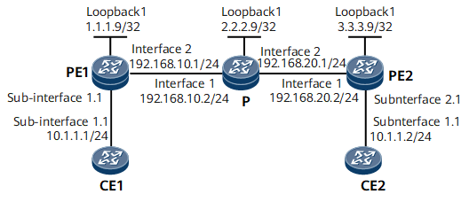
On the network shown in Figure 1, VPLS is enabled on PE1 and PE2. CE1 connects to PE1, CE2 connects to PE2, and CE1 and CE2 reside on the same VPLS network. If PE1 and PE2 are unable to support large numbers of LDP sessions or you want to manually manage and allocate VC labels, configure a static VPLS PW for CE1 and CE2 to communicate.

Configuration Notes
When configuring static VPLS, note the following:
- PEs belonging to the same L2VPN must have the same VSI ID.
Configuration Roadmap
The configuration roadmap is as follows:
Configure a routing protocol on the backbone network to implement interworking.
Establish tunnels between PEs for transmitting service data.
Enable MPLS L2VPN on the PEs.
Create a VSI on each PE, configure static VPLS, and bind the VSI to the AC interface.
Data Preparation
To complete the configuration, you need the following data:
VSI names and IDs
IP addresses and a tunnel policy used for setting up a peer relationship
Names of interfaces bound to the VSI
Procedure
- Assign an IP address to each interface on the PEs and P according to Figure 1, and configure an IGP. In this example, OSPF is used as the IGP protocol.
When configuring OSPF, advertise the 32-bit loopback interface addresses (LSR IDs) of PE1, P, and PE2.
For configuration details, see Configuration Files in this section.
After the configurations are completed, run the display ip routing-table command on PE1, P, and PE2. The command output shows the routes that the devices have learned from each other.
- Configure basic MPLS functions and LDP.
For configuration details, see Configuration Files in this section.
After completing the configuration, run the display mpls ldp session command on PE1, P, and PE2. The peer relationships have been set up between PE1 and P, and between P and PE2. The status of the peer relationship is Operational. Run the display mpls lsp command to view information about MPLS LSP establishment.
- Enable MPLS L2VPN on each PE.
# Configure PE1.
[~PE1] mpls l2vpn
[*PE1-l2vpn] commit
# Configure PE2.
[*PE2] mpls l2vpn
[*PE2-l2vpn] commit
- Configure a VSI on each PE.
# Configure PE1.
[~PE1] vsi a2
[*PE1-vsi-a2] pwsignal ldp
[*PE1-vsi-a2-ldp] vsi-id 2
[*PE1-vsi-a2-ldp] peer 3.3.3.9 static-upe trans 100 recv 100
[*PE1-vsi-a2-ldp] quit
[*PE1-vsi-a2] quit
[*PE1] commit
# Configure PE2.
[~PE2] vsi a2
[*PE2-vsi-a2] pwsignal ldp
[*PE2-vsi-a2-ldp] vsi-id 2
[*PE2-vsi-a2-ldp] peer 1.1.1.9 static-upe trans 100 recv 100
[*PE2-vsi-a2-ldp] quit
[*PE2-vsi-a2] quit
[*PE2] commit
- Bind an interface to the VSI on each PE.
# Configure PE1.
[~PE1] interface gigabitethernet0/1/0.1
[*PE1-GigabitEthernet0/1/0.1] shutdown
[*PE1-GigabitEthernet0/1/0.1] vlan-type dot1q 10
[*PE1-GigabitEthernet0/1/0.1] l2 binding vsi a2
[*PE1-GigabitEthernet0/1/0.1] undo shutdown
[*PE1-GigabitEthernet0/1/0.1] quit
[*PE1] commit
# Configure PE2.
[~PE2] interface gigabitethernet0/1/8.1
[*PE2-GigabitEthernet0/1/8.1] shutdown
[*PE2-GigabitEthernet0/1/8.1] vlan-type dot1q 10
[*PE2-GigabitEthernet0/1/8.1] l2 binding vsi a2
[*PE2-GigabitEthernet0/1/8.1] undo shutdown
[*PE2-GigabitEthernet0/1/8.1] quit
[*PE2] commit
- Configure CEs.
# Configure CE1.
<HUAWEI> system-view
[~HUAWEI] sysname CE1
[*HUAWEI] commit
[~CE1] interface gigabitethernet0/1/0.1
[*CE1-GigabitEthernet0/1/0.1] vlan-type dot1q 10
[*CE1-GigabitEthernet0/1/0.1] ip address 10.1.1.1 255.255.255.0
[*CE1-GigabitEthernet0/1/0.1] quit
[*CE1] commit
# Configure CE2.
<HUAWEI> system-view
[~HUAWEI] sysname CE2
[*HUAWEI] commit
[~CE2] interface gigabitethernet0/1/0.1
[*CE2-GigabitEthernet0/1/0.1] vlan-type dot1q 10
[*CE2-GigabitEthernet0/1/0.1] ip address 10.1.1.2 255.255.255.0
[*CE2-GigabitEthernet0/1/0.1] quit
[*CE2] commit
- Verify the configuration.
After completing the configuration, run the display vsi name a2 verbose command on PE1. You can see that the VSI named a2 has set up a PW to PE2 and the VSI status is up.
[~PE1] display vsi name a2 verbose
 ***VSI Name               : a2
    Administrator VSI      : no
    Isolate Spoken         : disable
    VSI Index              : 1
    PW Signaling           : --
    Member Discovery Style : --
    Bridge-domain Mode     : disable
    PW MAC Learning Style  : unqualify
    Encapsulation Type     : vlan
    MTU                    : 1500
    Diffserv Mode          : uniform
    Service Class          : --
    Color                  : --
    DomainId               : 255
    Domain Name            :
    Ignore AcState         : disable
    P2P VSI                : disable
    Multicast Fast Swicth  : disable
    Create Time            : 0 days, 0 hours, 7 minutes, 10 seconds
    VSI State              : up

    VSI ID                 : 2
   *Peer Router ID         : 3.3.3.9
    primary or secondary   : primary
    ignore-standby-state   : no
    VC Label               : 100
    Peer Type              : static
    Session                : up
    Tunnel ID              : 0x0000000001004c4b44
    Broadcast Tunnel ID    : --
    Broad BackupTunnel ID  : --
    CKey                   : 1
    NKey                   : 1610612838
    Stp Enable             : 0
    PwIndex                : 0

    Interface Name         : GigabitEthernet0/1/0.1
    State                  : up
    Access Port            : false
    Last Up Time           : 2012/09/10 10:14:46
    Total Up Time          : 0 days, 0 hours, 2 minutes, 14 seconds

  **PW Information:

   *Peer Ip Address        : 3.3.3.9
    PW State               : up
    Local VC Label         : 100
    Remote VC Label        : 100
    PW Type                : MEHVPLS
    Tunnel ID              : 0x0000000001004c4b44
    Broadcast Tunnel ID    : --
    Broad BackupTunnel ID  : --
    Ckey                   : 1
    Nkey                   : 1610612838
    Main PW Token          : 0x0
    Slave PW Token         : 0x0
    Tnl Type               : ldp
    OutInterface           : GigabitEthernet0/1/8
    Backup OutInterface    : --
    Stp Enable             : 0
    Mac Flapping           : 0
    PW Last Up Time        : 2012/09/10 10:16:03
    PW Total Up Time       : 0 days, 0 hours, 1 minutes, 19 seconds
# Configure CE1 (10.1.1.1) to ping CE2 (10.1.1.2). The ping is successful.
<CE1> ping 10.1.1.2
  PING 10.1.1.2: 56  data bytes, press CTRL_C to break
    Reply from 10.1.1.2: bytes=56 Sequence=1 ttl=255 time=90 ms
    Reply from 10.1.1.2: bytes=56 Sequence=2 ttl=255 time=77 ms
    Reply from 10.1.1.2: bytes=56 Sequence=3 ttl=255 time=34 ms
    Reply from 10.1.1.2: bytes=56 Sequence=4 ttl=255 time=46 ms
    Reply from 10.1.1.2: bytes=56 Sequence=5 ttl=255 time=94 ms
  --- 10.1.1.2 ping statistics ---
    5 packet(s) transmitted
    5 packet(s) received
    0.00% packet loss
    round-trip min/avg/max = 34/68/94 ms
Configuration Files
CE1 configuration file
#
 sysname CE1
#
interface GigabitEthernet0/1/0.1
 undo shutdown
 vlan-type dot1q 10
 ip address 10.1.1.1 255.255.255.0
#
return
CE2 configuration file
#
 sysname CE2
#
interface GigabitEthernet0/1/0.1
 undo shutdown
 vlan-type dot1q 10
 ip address 10.1.1.2 255.255.255.0
#
return
PE1 configuration file
#
 sysname PE1
#
 mpls lsr-id 1.1.1.9
 mpls
#
 mpls l2vpn
#
vsi a2
 pwsignal ldp
  vsi-id 2
  peer 3.3.3.9 static-upe trans 100 recv 100
#
mpls ldp
#
interface GigabitEthernet0/1/0.1
 undo shutdown
 vlan-type dot1q 10
 l2 binding vsi a2
#
interface GigabitEthernet0/1/8
 undo shutdown
 ip address 192.168.10.1 255.255.255.0
 mpls
 mpls ldp
#
interface LoopBack1
 ip address 1.1.1.9 255.255.255.255
#
ospf 1
 area 0.0.0.0
  network 1.1.1.9 0.0.0.0
  network 192.168.10.0 0.0.0.255
#
return
P configuration file
#
 sysname P
#
 mpls lsr-id 2.2.2.9
 mpls
#
mpls ldp
#
interface GigabitEthernet0/1/0
 undo shutdown
 ip address 192.168.10.2 255.255.255.0
 mpls
 mpls ldp
#
interface GigabitEthernet0/1/8
 undo shutdown
 ip address 192.168.20.1 255.255.255.0
 mpls
 mpls ldp
#
interface LoopBack1
 ip address 2.2.2.9 255.255.255.255
#
ospf 1
 area 0.0.0.0
  network 192.168.10.0 0.0.0.255
  network 192.168.20.0 0.0.0.255
  network 2.2.2.9 0.0.0.0
#
return
PE2 configuration file
#
 sysname PE2
#
 mpls lsr-id 3.3.3.9
 mpls
#
 mpls l2vpn
#
vsi a2
 pwsignal ldp
  vsi-id 2
  peer 1.1.1.9 static-upe trans 100 recv 100
#
mpls ldp
#
interface GigabitEthernet0/1/0
 undo shutdown
 ip address 192.168.20.2 255.255.255.0
 mpls
 mpls ldp
#
interface GigabitEthernet0/1/8.1
 undo shutdown
 vlan-type dot1q 10
 l2 binding vsi a2
#
interface LoopBack1
 ip address 3.3.3.9 255.255.255.255
#
ospf 1
 area 0.0.0.0
  network 3.3.3.9 0.0.0.0
  network 192.168.20.0 0.0.0.255
#
return