Example for Configuring LDP VPLS over TE (LDP)
A public network tunnel on an LDP VPLS network can be an MPLS TE tunnel.
Networking Requirements

Interface 1, interface 2, sub-interface 1.1, and sub-interface 2.1 in this example represent GE 0/1/0, GE 0/1/8, GE 0/1/0.1, and GE 0/1/8.1, respectively.
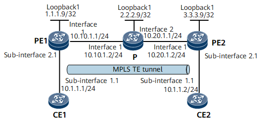
As shown in Figure 1, CE1 and CE2 belong to the same VPLS network and access the MPLS backbone network through PE1 and PE2, respectively. OSPF is used as the IGP on the MPLS backbone network.
It is required that LDP VPLS and the dynamic signaling protocol RSVP-TE be used to establish an MPLS TE tunnel between PE1 and PE2 to transmit VPLS services.
Configuration Notes
When configuring VPLS over TE (LDP mode), note the following:
- PEs belonging to the same VPLS network must have the same VSI ID.
Configuration Roadmap
The configuration roadmap is as follows:
Configure a routing protocol on PE and P devices of the backbone network to implement interworking, and enable MPLS.
Set up an MPLS TE tunnel and configure the tunnel policy. For details on how to set up an MPLS TE tunnel, see NetEngine 8000 F Configuration Guide - MPLS.
Enable MPLS L2VPN on the PEs.
Create VSIs on PEs, configure LDP as the signaling protocol, and bind VSIs to AC-side interfaces.
Configure the VSI to use an MPLS TE tunnel.
Data Preparation
To complete the configuration, you need the following data:
OSPF areas enabled with TE
VSI name and VSI ID
IP addresses of peers and tunnel policy
Name of each interface bound to the VSI
Procedure
- Assign IP addresses to interfaces and configure OSPF.
The configuration details are not provided.
- Configure MPLS, MPLS TE, MPLS RSVP-TE, and MPLS CSPF.
Enable MPLS, MPLS TE, and MPLS RSVP-TE both globally and on specific interfaces on each node along the MPLS TE tunnel. Enable MPLS TE CSPF in the system view of the tunnel's ingress.
# Configure PE1.
[~PE1] mpls lsr-id 1.1.1.9
[*PE1] mpls
[*PE1-mpls] mpls te
[*PE1-mpls] mpls rsvp-te
[*PE1-mpls] mpls te cspf
[*PE1-mpls] quit
[*PE1] interface gigabitethernet0/1/0
[*PE1-GigabitEthernet0/1/0] mpls
[*PE1-GigabitEthernet0/1/0] mpls te
[*PE1-GigabitEthernet0/1/0] mpls rsvp-te
[*PE1-GigabitEthernet0/1/0] quit
[*PE1] commit
# Configure the P.
[~P] mpls lsr-id 2.2.2.9
[*P] mpls
[*P-mpls] mpls te
[*P-mpls] mpls rsvp-te
[*P-mpls] quit
[*P] interface gigabitethernet0/1/0
[*P-GigabitEthernet0/1/0] mpls
[*P-GigabitEthernet0/1/0] mpls te
[*P-GigabitEthernet0/1/0] mpls rsvp-te
[*P-GigabitEthernet0/1/0] quit
[*P] interface gigabitethernet0/1/8
[*P-GigabitEthernet0/1/8] mpls
[*P-GigabitEthernet0/1/8] mpls te
[*P-GigabitEthernet0/1/8] mpls rsvp-te
[*P-GigabitEthernet0/1/8] quit
[*P] commit
# Configure PE2.
[~PE2] mpls lsr-id 3.3.3.9
[*PE2] mpls
[*PE2-mpls] mpls te
[*PE2-mpls] mpls rsvp-te
[*PE2-mpls] mpls te cspf
[*PE2-mpls] quit
[*PE2] interface gigabitethernet0/1/0
[*PE2-GigabitEthernet0/1/0] mpls
[*PE2-GigabitEthernet0/1/0] mpls te
[*PE2-GigabitEthernet0/1/0] mpls rsvp-te
[*PE2-GigabitEthernet0/1/0] quit
[*PE2] commit
- Configure OSPF TE on the backbone network.
# Configure PE1.
[~PE1] ospf
[*PE1-ospf-1] opaque-capability enable
[*PE1-ospf-1] area 0.0.0.0
[*PE1-ospf-1-area-0.0.0.0] network 1.1.1.9 0.0.0.0
[*PE1-ospf-1-area-0.0.0.0] network 10.10.1.0 0.0.0.255
[*PE1-ospf-1-area-0.0.0.0] mpls-te enable
[*PE1-ospf-1-area-0.0.0.0] quit
[*PE1-ospf-1] quit
[*PE1] commit
# Configure the P.
[~P] ospf
[*P-ospf-1] opaque-capability enable
[*P-ospf-1] area 0.0.0.0
[*P-ospf-1-area-0.0.0.0] network 2.2.2.9 0.0.0.0
[*P-ospf-1-area-0.0.0.0] network 10.10.1.0 0.0.0.255
[*P-ospf-1-area-0.0.0.0] network 10.20.1.0 0.0.0.255
[*P-ospf-1-area-0.0.0.0] mpls-te enable
[*P-ospf-1-area-0.0.0.0] quit
[*P-ospf-1] quit
[*P] commit
# Configure PE2.
[~PE2] ospf
[*PE2-ospf-1] opaque-capability enable
[*PE2-ospf-1] area 0.0.0.0
[*PE2-ospf-1-area-0.0.0.0] network 3.3.3.9 0.0.0.0
[*PE2-ospf-1-area-0.0.0.0] network 10.20.1.0 0.0.0.255
[*PE2-ospf-1-area-0.0.0.0] mpls-te enable
[*PE2-ospf-1-area-0.0.0.0] quit
[*PE2-ospf-1] quit
[*PE2] commit
- Configure a tunnel interface on each device.
# Create tunnel interfaces on PEs and specify MPLS TE as the tunnel protocol and RSVP-TE as the signaling protocol.
# Configure PE1.
[~PE1] interface Tunnel 10
[*PE1-Tunnel10] ip address unnumbered interface loopback1
[*PE1-Tunnel10] tunnel-protocol mpls te
[*PE1-Tunnel10] destination 3.3.3.9
[*PE1-Tunnel10] mpls te tunnel-id 100
[*PE1-Tunnel10] mpls te reserved-for-binding
[*PE1-Tunnel10] quit
[*PE1] commit
# Configure PE2.
[~PE2] interface Tunnel 10
[*PE2-Tunnel10] ip address unnumbered interface loopback1
[*PE2-Tunnel10] tunnel-protocol mpls te
[*PE2-Tunnel10] destination 1.1.1.9
[*PE2-Tunnel10] mpls te tunnel-id 100
[*PE2-Tunnel10] mpls te reserved-for-binding
[*PE2-Tunnel10] quit
[*PE2] commit
After completing the preceding configurations, run the display this interface command in the tunnel interface view. The command output shows that Line protocol current state is UP, indicating that an MPLS TE tunnel has been established. The following example uses the command output on PE1.
[~PE1-Tunnel10] display this interface
Tunnel10 current state : UP (ifindex: 20)
Line protocol current state : UP
Last line protocol up time : 2012-09-11 08:25:42
Description:
Route Port,The Maximum Transmit Unit is 1500
Internet Address is unnumbered, using address of LoopBack1(1.1.1.9/32)
Encapsulation is TUNNEL, loopback not set
Tunnel destination 3.3.3.9
Tunnel up/down statistics 1
Tunnel protocol/transport MPLS/MPLS, ILM is available,
primary tunnel id is 0x33, secondary tunnel id is 0x0
Current system time: 2012-09-11 08:27:00
    0 seconds output rate 0 bits/sec, 0 packets/sec
    0 seconds output rate 0 bits/sec, 0 packets/sec
    0 packets output,  0 bytes
    0 output error
    0 output drop
    Last 300 seconds input utility rate:  0.00%
    Last 300 seconds output utility rate: 0.00%
Run the display tunnel-info all command in the system view. The TE tunnel whose destination address is the MPLS LSR ID of the peer PE exists. The following example uses the command output on PE1.
[~PE1] display tunnel-info all Tunnel ID Type Destination Status ----------------------------------------------------------------------------- 0x000000000300000001 te 3.3.3.9 UP - Configure remote LDP sessions.
Set up a remote peer session between PE1 and PE2.
# Configure PE1.
[~PE1] mpls ldp
[*PE1-mpls-ldp] quit
[*PE1] mpls ldp remote-peer 3.3.3.9
[*PE1-mpls-ldp-remote-3.3.3.9] remote-ip 3.3.3.9
[*PE1-mpls-ldp-remote-3.3.3.9] quit
[*PE1] commit
# Configure PE2.
[~PE2] mpls ldp
[*PE2-mpls-ldp] quit
[*PE2] mpls ldp remote-peer 1.1.1.9
[*PE2-mpls-ldp-remote-1.1.1.9] remote-ip 1.1.1.9
[*PE2-mpls-ldp-remote-1.1.1.9] quit
[*PE2] commit
- Configure a tunnel policy.
# Configure PE1.
[~PE1] tunnel-policy policy1
[*PE1-tunnel-policy-policy1] tunnel binding destination 3.3.3.9 te Tunnel10
[*PE1-tunnel-policy-policy1] quit
[*PE1] commit
# Configure PE2.
[~PE2] tunnel-policy policy1
[*PE2-tunnel-policy-policy1] tunnel binding destination 1.1.1.9 te Tunnel10
[*PE2-tunnel-policy-policy1] quit
[*PE2] commit
- Enable MPLS L2VPN on each PE.
# Configure PE1.
[~PE1] mpls l2vpn
[*PE1] commit
# Configure PE2.
[~PE2] mpls l2vpn
[*PE2] commit
- Create VSIs on PEs and bind the tunnel policy to the VSIs.
# Configure PE1.
[~PE1] vsi a2
[*PE1-vsi-a2] pwsignal ldp
[*PE1-vsi-a2-ldp] vsi-id 2
[*PE1-vsi-a2-ldp] peer 3.3.3.9 tnl-policy policy1
[*PE1-vsi-a2-ldp] quit
[*PE1] commit
# Configure PE2.
[~PE2] vsi a2
[*PE2-vsi-a2] pwsignal ldp
[*PE2-vsi-a2-ldp] vsi-id 2
[*PE2-vsi-a2-ldp] peer 1.1.1.9 tnl-policy policy1
[*PE2-vsi-a2-ldp] quit
[*PE2] commit
- Bind an interface to the VSI on each PE.
# Configure PE1.
[~PE1] interface gigabitethernet0/1/8.1
[*PE1-GigabitEthernet0/1/8.1] vlan-type dot1q 10
[*PE1-GigabitEthernet0/1/8.1] l2 binding vsi a2
[*PE1-GigabitEthernet0/1/8.1] quit
[*PE1] commit
# Configure PE2.
[~PE2] interface gigabitethernet0/1/8.1
[*PE2-GigabitEthernet0/1/8.1] vlan-type dot1q 10
[*PE2-GigabitEthernet0/1/8.1] l2 binding vsi a2
[*PE2-GigabitEthernet0/1/8.1] quit
[*PE2] commit
# Configure CE1.
[~CE1] interface gigabitethernet0/1/0.1
[*CE1-GigabitEthernet0/1/0.1] vlan-type dot1q 10
[*CE1-GigabitEthernet0/1/0.1] ip address 10.1.1.1 255.255.255.0
[*CE1-GigabitEthernet0/1/0.1] quit
[*CE1] commit
# Configure CE2.
[~CE2] interface gigabitethernet0/1/0.1
[*CE2-GigabitEthernet0/1/0.1] vlan-type dot1q 10
[*CE2-GigabitEthernet0/1/0.1] ip address 10.1.1.2 255.255.255.0
[*CE2-GigabitEthernet0/1/0.1] quit
[*CE2] commit
- Verify the configuration.
After completing the configuration, run the display vsi name a2 verbose command on PE1. The VSI named a2 has set up a PW to PE2 and the VSI status is up.
[~PE1] display vsi name a2 verbose
 ***VSI Name               : a2
    Administrator VSI      : no
    Isolate Spoken         : disable
    VSI Index              : 1
    PW Signaling           : ldp
    Member Discovery Style : --
    Bridge-domain Mode     : disable
    PW MAC Learning Style  : unqualify
    Encapsulation Type     : vlan
    MTU                    : 1500
    Diffserv Mode          : uniform
    Service Class          : --
    Color                  : --
    DomainId               : 255
    Domain Name            :
    Ignore AcState         : disable
    P2P VSI                : disable
    Create Time            : 1 days, 8 hours, 46 minutes, 34 seconds
    VSI State              : up
    Resource Status        : --

    VSI ID                 : 2
   *Peer Router ID         : 3.3.3.9
    primary or secondary   : primary
    ignore-standby-state   : no
    VC Label               : 18
    Peer Type              : dynamic
    Session                : up
    Tunnel ID              : 0x000000000300000001
    Broadcast Tunnel ID    : --
    Broad BackupTunnel ID  : --
    Tunnel Policy Name     : policy1
    CKey                   : 33
    NKey                   : 1610612843
    Stp Enable             : 0
    PwIndex                : 0
    Control Word           : disable

    Interface Name         : GigabitEthernet0/1/8.1
    State                  : up
    Access Port            : false
    Last Up Time           : 2012/09/10 10:14:46
    Total Up Time          : 1 days, 8 hours, 41 minutes, 37 seconds

  **PW Information:

   *Peer Ip Address        : 3.3.3.9
    PW State               : up
    Local VC Label         : 18
    Remote VC Label        : 18
    Remote Control Word    : disable
    PW Type                : label
    Tunnel ID              : 0x000000000300000001
    Broadcast Tunnel ID    : --
    Broad BackupTunnel ID  : --
    Ckey                   : 33
    Nkey                   : 1610612843
    Main PW Token          : 0x0
    Slave PW Token         : 0x0
    Tnl Type               : te
    OutInterface           : Tunnel10
    Backup OutInterface    : --
    Stp Enable             : 0
    PW Last Up Time        : 2012/09/11 09:19:12
    PW Total Up Time       : 1 days, 6 hours, 52 minutes, 3 seconds
Run the display mpls lsp include 3.3.3.9 32 verbose command on PE1. The command output shows information about the LSP to 3.3.3.9/32.
[~PE1] display mpls lsp include 3.3.3.9 32 verbose
----------------------------------------------------------------------
                 LSP Information: RSVP LSP
----------------------------------------------------------------------
  No                  :  1
  SessionID           :  100
  IngressLsrID        :  1.1.1.9
  LocalLspID          :  1
  Tunnel-Interface    :  Tunnel10
  Fec                 :  3.3.3.9/32
  Nexthop             :  10.10.1.2
  In-Label            :  NULL
  Out-Label           :  97
  In-Interface        :  ----------
  Out-Interface       :  GigabitEthernet0/1/0
  LspIndex            :  33
  Token               :  ----------
  LsrType             :  Ingress
  Mpls-Mtu            :  1500
  LspAge              :  4739 sec
Run the display vsi pw out-interface vsi a2 command on PE1. The command output shows that the outbound interface of the MPLS TE tunnel between 1.1.1.9 and 3.3.3.9 is Tunnel10.
[~PE1] display vsi pw out-interface vsi a2
Total: 1
--------------------------------------------------------------------------------
Vsi Name                        peer            vcid       interface
--------------------------------------------------------------------------------
a2                              3.3.3.9         2          Tunnel10
Configure CE1 and CE2 to ping each other. The pings are successful.
<CE1> ping 10.1.1.2
  PING 10.1.1.2: 56  data bytes, press CTRL_C to break
    Reply from 10.1.1.2: bytes=56 Sequence=1 ttl=255 time=125 ms
    Reply from 10.1.1.2: bytes=56 Sequence=2 ttl=255 time=125 ms
    Reply from 10.1.1.2: bytes=56 Sequence=3 ttl=255 time=94 ms
    Reply from 10.1.1.2: bytes=56 Sequence=4 ttl=255 time=125 ms
    Reply from 10.1.1.2: bytes=56 Sequence=5 ttl=255 time=125 ms
  --- 10.1.1.2 ping statistics ---
    5 packet(s) transmitted
    5 packet(s) received
    0.00% packet loss
    round-trip min/avg/max = 94/118/125 ms
Configuration Files
CE1 configuration file
#
 sysname CE1
#
interface GigabitEthernet0/1/0.1
 undo shutdown
 vlan-type dot1q 10
 ip address 10.1.1.1 255.255.255.0
#
return
PE1 configuration file
#
 sysname PE1
#
 mpls lsr-id 1.1.1.9
 mpls
  mpls te
  mpls rsvp-te
  mpls te cspf
#
 mpls l2vpn
#
vsi a2
 pwsignal ldp
  vsi-id 2
  peer 3.3.3.9 tnl-policy policy1
#
mpls ldp
#
 mpls ldp remote-peer 3.3.3.9
 remote-ip 3.3.3.9
#
interface GigabitEthernet0/1/8.1
 undo shutdown
 vlan-type dot1q 10
 l2 binding vsi a2
#
interface GigabitEthernet0/1/0
 undo shutdown
 ip address 10.10.1.1 255.255.255.0
 ospf cost 1
 mpls
 mpls te
 mpls rsvp-te
#
interface LoopBack1
 ip address 1.1.1.9 255.255.255.255
#
interface Tunnel10
 ip address unnumbered interface LoopBack1
 tunnel-protocol mpls te
 destination 3.3.3.9
 mpls te tunnel-id 100
 mpls te reserved-for-binding
#
ospf 1
 opaque-capability enable
 area 0.0.0.0
  network 1.1.1.9 0.0.0.0
  network 10.10.1.0 0.0.0.255
  mpls-te enable
#
tunnel-policy  policy1
 tunnel binding destination 3.3.3.9 te Tunnel10
#
return
P configuration file
#
 sysname P
#
 mpls lsr-id 2.2.2.9
 mpls
  mpls te
  mpls rsvp-te
#
interface GigabitEthernet0/1/0
 undo shutdown
 ip address 10.10.1.2 255.255.255.0
 ospf cost 1
 mpls
 mpls te
 mpls rsvp-te
#
interface GigabitEthernet0/1/8
 undo shutdown
 ip address 10.20.1.1 255.255.255.0
 ospf cost 1
 mpls
 mpls te
 mpls rsvp-te
#
interface LoopBack1
 ip address 2.2.2.9 255.255.255.255
#
ospf 1
 opaque-capability enable
 area 0.0.0.0
  network 2.2.2.9 0.0.0.0
  network 10.10.1.0 0.0.0.255
  network 10.20.1.0 0.0.0.255
  mpls-te enable
#
return
PE2 configuration file
#
 sysname PE2
#
 mpls lsr-id 3.3.3.9
 mpls
  mpls te
  mpls rsvp-te
  mpls te cspf
#
 mpls l2vpn
#
vsi a2
 pwsignal ldp
  vsi-id 2
  peer 1.1.1.9 tnl-policy policy1
#
mpls ldp
#
 mpls ldp remote-peer 1.1.1.9
 remote-ip 1.1.1.9
#
interface GigabitEthernet0/1/8.1
 undo shutdown
 vlan-type dot1q 10
 l2 binding vsi a2
#
interface GigabitEthernet0/1/0
 undo shutdown
 ip address 10.20.1.2 255.255.255.0
 ospf cost 1
 mpls
 mpls te
 mpls rsvp-te
#
interface LoopBack1
 ip address 3.3.3.9 255.255.255.255
#
interface Tunnel10
 ip address unnumbered interface LoopBack1
 tunnel-protocol mpls te
 destination 1.1.1.9
 mpls te tunnel-id 100
 mpls te reserved-for-binding
#
ospf 1
 opaque-capability enable
 area 0.0.0.0
  network 3.3.3.9 0.0.0.0
  network 10.20.1.0 0.0.0.255
  mpls-te enable
#
tunnel-policy  policy1
 tunnel binding destination 1.1.1.9 te Tunnel10
#
return
CE2 configuration file
#
 sysname CE2
#
interface GigabitEthernet0/1/0.1
 undo shutdown
 vlan-type dot1q 10
 ip address 10.1.1.2 255.255.255.0
#
return