Example for Configuring LDP VPLS over SR-MPLS TE
The public network tunnel for an LDP VPLS network can be an SR-MPLS TE tunnel.
Networking Requirements
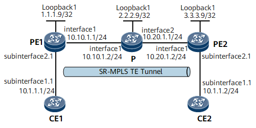
On the network shown in Figure 1, CE1 and CE2 are on the same VPLS network. They access the MPLS core network through PE1 and PE2 respectively. OSPF is used as the IGP on the MPLS backbone network.
LDP VPLS and an SR-MPLS TE tunnel must be deployed between PE1 and PE2 to transmit VPLS services.
Configuration Notes
When configuring LDP VPLS over SR-MPLS TE, note that PEs on the same L2VPN must be configured with the same VSI ID.
Configuration Roadmap
The configuration roadmap is as follows:
Configure a routing protocol on the backbone devices (PEs and the P) to achieve connectivity and enable MPLS.
Set up an SR-MPLS TE tunnel and configure the tunnel policy. For configuration details, see the NetEngine 8000 FConfiguration Guide - Segment Routing.
Create VSIs on PEs, set the signaling protocol to LDP, and bind VSIs to AC interfaces.
Procedure
- Assign IP addresses to interfaces.
# Configure PE1.
<HUAWEI> system-view
[~HUAWEI] sysname PE1
[*HUAWEI] commit
[~PE1] interface loopback 1
[*PE1-LoopBack1] ip address 1.1.1.9 32
[*PE1-LoopBack1] quit
[*PE1] interface gigabitethernet0/1/0
[*PE1-GigabitEthernet0/1/0] ip address 10.10.1.1 24
[*PE1-GigabitEthernet0/1/0] quit
[*PE1] commit
# Configure P.
<HUAWEI> system-view
[~HUAWEI] sysname P
[*HUAWEI] commit
[~P] interface loopback 1
[*P-LoopBack1] ip address 2.2.2.9 32
[*P-LoopBack1] quit
[*P] interface gigabitethernet0/1/0
[*P-GigabitEthernet0/1/0] ip address 10.10.1.2 24
[*P-GigabitEthernet0/1/0] quit
[*P] interface gigabitethernet0/1/8
[*P-GigabitEthernet0/1/8] ip address 10.20.1.1 24
[*P-GigabitEthernet0/1/8] quit
[*P] commit
# Configure PE2.
<HUAWEI> system-view
[~HUAWEI] sysname PE2
[*HUAWEI] commit
[~PE2] interface loopback 1
[*PE2-LoopBack1] ip address 3.3.3.9 32
[*PE2-LoopBack1] quit
[*PE2] interface gigabitethernet0/1/0
[*PE2-GigabitEthernet0/1/0] ip address 10.20.1.2 24
[*PE2-GigabitEthernet0/1/0] quit
[*PE2] commit
- Configure MPLS and MPLS TE.
On the nodes along the MPLS TE tunnel, configure MPLS and MPLS TE globally.
# Configure PE1.
[~PE1] mpls lsr-id 1.1.1.9
[*PE1] mpls
[*PE1-mpls] mpls te
[*PE1-mpls] quit
[*PE1] commit
# Configure the P.
[~P] mpls lsr-id 2.2.2.9
[*P] mpls
[*P-mpls] mpls te
[*P-mpls] quit
[*P] commit
# Configure PE2.
[~PE2] mpls lsr-id 3.3.3.9
[*PE2] mpls
[*PE2-mpls] mpls te
[*PE2-mpls] quit
[*PE2] commit
- Configure OSPF TE on the backbone network.
# Configure PE1.
[~PE1] ospf 1
[*PE1-ospf-1] opaque-capability enable
[*PE1-ospf-1] area 0.0.0.0
[*PE1-ospf-1-area-0.0.0.0] network 1.1.1.9 0.0.0.0
[*PE1-ospf-1-area-0.0.0.0] network 10.10.1.0 0.0.0.255
[*PE1-ospf-1-area-0.0.0.0] mpls-te enable
[*PE1-ospf-1-area-0.0.0.0] quit
[*PE1-ospf-1] quit
[*PE1] commit
# Configure the P.
[~P] ospf 1
[*P-ospf-1] opaque-capability enable
[*P-ospf-1] area 0.0.0.0
[*P-ospf-1-area-0.0.0.0] network 2.2.2.9 0.0.0.0
[*P-ospf-1-area-0.0.0.0] network 10.10.1.0 0.0.0.255
[*P-ospf-1-area-0.0.0.0] network 10.20.1.0 0.0.0.255
[*P-ospf-1-area-0.0.0.0] mpls-te enable
[*P-ospf-1-area-0.0.0.0] quit
[*P-ospf-1] quit
[*P] commit
# Configure PE2.
[~PE2] ospf 1
[*PE2-ospf-1] opaque-capability enable
[*PE2-ospf-1] area 0.0.0.0
[*PE2-ospf-1-area-0.0.0.0] network 3.3.3.9 0.0.0.0
[*PE2-ospf-1-area-0.0.0.0] network 10.20.1.0 0.0.0.255
[*PE2-ospf-1-area-0.0.0.0] mpls-te enable
[*PE2-ospf-1-area-0.0.0.0] quit
[*PE2-ospf-1] quit
[*PE2] commit
- Configure Segment Routing on the backbone network.
# Configure PE1.
[~PE1] segment-routing
[*PE1-segment-routing] quit
[*PE1] ospf 1
[*PE1-ospf-1] segment-routing mpls
[*PE1-ospf-1] segment-routing global-block 16000 47999

The value range of SRGB changes dynamically, depending on the actual situation of the equipment. Here is an example only.
[*PE1-ospf-1] quit
[*PE1] interface loopback 1
[*PE1-LoopBack1] ospf prefix-sid absolute 16100
[*PE1-LoopBack1] quit
[*PE1] commit
# Configure the P.
[~P] segment-routing
[*P1-segment-routing] quit
[*P] ospf 1
[*P-ospf-1] segment-routing mpls
[*P-ospf-1] segment-routing global-block 16000 47999
The value range of SRGB changes dynamically, depending on the actual situation of the equipment. Here is an example only.
[*P-ospf-1] quit
[*P] interface loopback 1
[*P-LoopBack1] ospf prefix-sid absolute 16300
[*P-LoopBack1] quit
[*P] commit
# Configure PE2.
[~PE2] segment-routing
[*PE2-segment-routing] quit
[*PE2] ospf 1
[*PE2-ospf-1] segment-routing mpls
[*PE2-ospf-1] segment-routing global-block 16000 47999
[*PE2-ospf-1] quit[*PE2] interface loopback 1[*PE2-LoopBack1] ospf prefix-sid absolute 16200[*PE2-LoopBack1] quit[*PE2] commit - Configure explicit paths.
# Configure PE1.
[~PE1] explicit-path path2pe2
[*PE1-explicit-path-path2pe2] next sid label 16300 type prefix
[*PE1-explicit-path-path2pe2] next sid label 16200 type prefix
[*PE1-explicit-path-path2pe2] quit
[*PE1] commit
# Configure PE2.
[~PE2] explicit-path path2pe1
[*PE2-explicit-path-path2pe1] next sid label 16300 type prefix
[*PE2-explicit-path-path2pe1] next sid label 16100 type prefix
[*PE2-explicit-path-path2pe1] quit
[*PE2] commit
- Configure tunnel interfaces.
# Create tunnel interfaces on PEs. Specify MPLS TE as the tunneling protocol and Segment Routing as the signaling protocol.
# Configure PE1.
[~PE1] interface Tunnel 10
[*PE1-Tunnel10] ip address unnumbered interface loopback1
[*PE1-Tunnel10] tunnel-protocol mpls te
[*PE1-Tunnel10] destination 3.3.3.9
[*PE1-Tunnel10] mpls te signal-protocol segment-routing
[*PE1-Tunnel10] mpls te tunnel-id 100
[*PE1-Tunnel10] mpls te path explicit-path path2pe2
[*PE1-Tunnel10] mpls te reserved-for-binding
[*PE1-Tunnel10] quit
[*PE1] commit
# Configure PE2.
[~PE2] interface Tunnel 10
[*PE2-Tunnel10] ip address unnumbered interface loopback1
[*PE2-Tunnel10] tunnel-protocol mpls te
[*PE2-Tunnel10] destination 1.1.1.9
[*PE2-Tunnel10] mpls te signal-protocol segment-routing
[*PE2-Tunnel10] mpls te tunnel-id 100
[*PE2-Tunnel10] mpls te path explicit-path path2pe1
[*PE2-Tunnel10] mpls te reserved-for-binding
[*PE2-Tunnel10] quit
[*PE2] commit
Run the display tunnel-info all command in the system view. The command output shows that the TE tunnel with the destination address being the peer MPLS LSR ID exists between PEs. The following example uses the command output on PE1.
[~PE1] display tunnel-info all Tunnel ID Type Destination Status ----------------------------------------------------------------------------- 0x000000000300000001 sr-te 3.3.3.9 UP - Configure remote LDP sessions.
Set up remote peer sessions between PE1 and PE2.
# Configure PE1.
[~PE1] mpls ldp
[*PE1-mpls-ldp] quit
[*PE1] mpls ldp remote-peer 3.3.3.9
[*PE1-mpls-ldp-remote-3.3.3.9] remote-ip 3.3.3.9
[*PE1-mpls-ldp-remote-3.3.3.9] quit
[*PE1] commit
# Configure PE2.
[~PE2] mpls ldp
[*PE2-mpls-ldp] quit
[*PE2] mpls ldp remote-peer 1.1.1.9
[*PE2-mpls-ldp-remote-1.1.1.9] remote-ip 1.1.1.9
[*PE2-mpls-ldp-remote-1.1.1.9] quit
[*PE2] commit
- Configure the tunnel policy.
# Configure PE1.
[~PE1] tunnel-policy policy1
[*PE1-tunnel-policy-policy1] tunnel binding destination 3.3.3.9 te Tunnel10
[*PE1-tunnel-policy-policy1] quit
[*PE1] commit
# Configure PE2.
[~PE2] tunnel-policy policy1
[*PE2-tunnel-policy-policy1] tunnel binding destination 1.1.1.9 te Tunnel10
[*PE2-tunnel-policy-policy1] quit
[*PE2] commit
- Enable MPLS L2VPN on PEs.
# Configure PE1.
[~PE1] mpls l2vpn
[*PE1-l2vpn] quit
[*PE1] commit
# Configure PE2.
[~PE2] mpls l2vpn
[*PE2-l2vpn] quit
[*PE2] commit
- Create VSIs on PEs and bind the tunnel policy to the VSIs.
# Configure PE1.
[~PE1] vsi a2
[*PE1-vsi-a2] pwsignal ldp
[*PE1-vsi-a2-ldp] vsi-id 2
[*PE1-vsi-a2-ldp] peer 3.3.3.9 tnl-policy policy1
[*PE1-vsi-a2-ldp] quit
[*PE1-vsi-a2] quit
[*PE1] commit
# Configure PE2.
[~PE2] vsi a2
[*PE2-vsi-a2] pwsignal ldp
[*PE2-vsi-a2-ldp] vsi-id 2
[*PE2-vsi-a2-ldp] peer 1.1.1.9 tnl-policy policy1
[*PE2-vsi-a2-ldp] quit
[*PE2-vsi-a2] quit
[*PE2] commit
- Bind VSIs to AC interfaces on PEs.
# Configure PE1.
[~PE1] interface gigabitethernet0/1/8.1
[*PE1-GigabitEthernet0/1/8.1] vlan-type dot1q 10
[*PE1-GigabitEthernet0/1/8.1] l2 binding vsi a2
[*PE1-GigabitEthernet0/1/8.1] quit
[*PE1] commit
# Configure PE2.
[~PE2] interface gigabitethernet0/1/8.1
[*PE2-GigabitEthernet0/1/8.1] vlan-type dot1q 10
[*PE2-GigabitEthernet0/1/8.1] l2 binding vsi a2
[*PE2-GigabitEthernet0/1/8.1] quit
[*PE2] commit
# Configure CE1.
[~CE1] interface gigabitethernet0/1/0.1
[*CE1-GigabitEthernet0/1/0.1] vlan-type dot1q 10
[*CE1-GigabitEthernet0/1/0.1] ip address 10.1.1.1 255.255.255.0
[*CE1-GigabitEthernet0/1/0.1] quit
[*CE1] commit
# Configure CE2.
[~CE2] interface gigabitethernet0/1/0.1
[*CE2-GigabitEthernet0/1/0.1] vlan-type dot1q 10
[*CE2-GigabitEthernet0/1/0.1] ip address 10.1.1.2 255.255.255.0
[*CE2-GigabitEthernet0/1/0.1] quit
[*CE2] commit
- Verify the configuration.
After completing the configurations, run the display vsi name a2 verbose command on PE1. The command output shows that the VSI named a2 has established a PW to PE2, and the status of the VSI is up.
[~PE1] display vsi name a2 verbose
 ***VSI Name               : a2
    Work Mode              : normal
    Administrator VSI      : no
    Isolate Spoken         : disable
    VSI Index              : 1
    PW Signaling           : ldp
    Member Discovery Style : --
    Bridge-domain Mode     : disable
    PW MAC Learn Style     : unqualify
    Encapsulation Type     : vlan
    MTU                    : 1500
    Diffserv Mode          : uniform
    Service Class          : --
    Color                  : --
    DomainId               : 255
    Domain Name            :
    Ignore AcState         : disable
    P2P VSI                : disable
    Multicast Fast Switch  : disable
    Create Time            : 1 days, 8 hours, 46 minutes, 34 seconds
    VSI State              : up
    Resource Status        : --

    VSI ID                 : 2
   *Peer Router ID         : 3.3.3.9
    Negotiation-vc-id      : 2
    Encapsulation Type     : vlan
    primary or secondary   : primary
    ignore-standby-state   : no
    VC Label               : 18
    Peer Type              : dynamic
    Session                : up
    Tunnel ID              : 0x000000000300000001
    Broadcast Tunnel ID    : --
    Broad BackupTunnel ID  : --
    Tunnel Policy Name     : policy1
    CKey                   : 33
    NKey                   : 1610612843
    Stp Enable             : 0
    PwIndex                : 0
    Control Word           : disable
    BFD for PW             : unavailable

    Interface Name         : GigabitEthernet0/1/8.1
    State                  : up
    Ac Block State         : unblocked
    Access Port            : false
    Last Up Time           : 2012/09/10 10:14:46
    Total Up Time          : 1 days, 8 hours, 41 minutes, 37 seconds

  **PW Information:

   *Peer Ip Address        : 3.3.3.9
    PW State               : up
    Local VC Label         : 18
    Remote VC Label        : 18
    Remote Control Word    : disable
    PW Type                : label
    Local  VCCV            : alert lsp-ping bfd
    Remote VCCV            : alert lsp-ping bfd
    Tunnel ID              : 0x000000000300000001
    Broadcast Tunnel ID    : --
    Broad BackupTunnel ID  : --
    Ckey                   : 33
    Nkey                   : 1610612843
    Main PW Token          : 0x0
    Slave PW Token         : 0x0
    Tnl Type               : te
    OutInterface           : Tunnel10
    Backup OutInterface    : --
    Stp Enable             : 0
    Mac Flapping           : 0
    Monitor Group Name     : --
    PW Last Up Time        : 2012/09/11 09:19:12
    PW Total Up Time       : 1 days, 6 hours, 52 minutes, 3 seconds
Run the display vsi pw out-interface vsi a2 command on PE2. The command output shows that the outbound interface of the MPLS TE tunnel between 1.1.1.9 and 3.3.3.9 is Tunnel 10.
[~PE1] display vsi pw out-interface vsi a2
Total: 1
--------------------------------------------------------------------------------
Vsi Name                        peer            vcid       interface
--------------------------------------------------------------------------------
a2                              3.3.3.9         2          Tunnel10
CE1 and CE2 can ping each other.
[~CE1] ping 10.1.1.2
  PING 10.1.1.2: 56  data bytes, press CTRL_C to break
    Reply from 10.1.1.2: bytes=56 Sequence=1 ttl=255 time=125 ms
    Reply from 10.1.1.2: bytes=56 Sequence=2 ttl=255 time=125 ms
    Reply from 10.1.1.2: bytes=56 Sequence=3 ttl=255 time=94 ms
    Reply from 10.1.1.2: bytes=56 Sequence=4 ttl=255 time=125 ms
    Reply from 10.1.1.2: bytes=56 Sequence=5 ttl=255 time=125 ms
  --- 10.1.1.2 ping statistics ---
    5 packet(s) transmitted
    5 packet(s) received
    0.00% packet loss
    round-trip min/avg/max = 94/118/125 ms
Configuration Files
-
#
sysname CE1
#
interface GigabitEthernet0/1/0
 undo shutdown
#
interface GigabitEthernet0/1/0.1
 vlan-type dot1q 10
 ip address 10.1.1.1 255.255.255.0
#
return
-
#
sysname PE1
#
mpls lsr-id 1.1.1.9
#
mpls
 mpls te
#
mpls l2vpn
#
vsi a2
 pwsignal ldp
  vsi-id 2
  peer 3.3.3.9 tnl-policy policy1
#
explicit-path path2pe2
 next sid label 16300 type prefix
 next sid label 16200 type prefix
#
mpls ldp
 #
 ipv4-family
#
mpls ldp remote-peer 3.3.3.9
 remote-ip 3.3.3.9
#
segment-routing
#
interface GigabitEthernet0/1/0
 undo shutdown
 ip address 10.10.1.1 255.255.255.0
#
interface GigabitEthernet0/1/8
 undo shutdown
#
interface GigabitEthernet0/1/8.1
 vlan-type dot1q 10
 l2 binding vsi a2
#
interface LoopBack1
 ip address 1.1.1.9 255.255.255.255
 ospf prefix-sid absolute 16100
#
interface Tunnel10
 ip address unnumbered interface LoopBack1
 tunnel-protocol mpls te
 destination 3.3.3.9
 mpls te signal-protocol segment-routing
 mpls te reserved-for-binding
 mpls te tunnel-id 100
 mpls te path explicit-path path2pe2
#
ospf 1
 opaque-capability enable
 segment-routing mpls
 segment-routing global-block 16000 47999
 area 0.0.0.0
  network 1.1.1.9 0.0.0.0
  network 10.10.1.0 0.0.0.255
  mpls-te enable
#
tunnel-policy policy1
 tunnel binding destination 3.3.3.9 te Tunnel10
#
return
-
#
sysname P
#
mpls lsr-id 2.2.2.9
#
mpls
 mpls te
#
segment-routing
#
interface GigabitEthernet0/1/0
 undo shutdown
 ip address 10.10.1.2 255.255.255.0
#
interface GigabitEthernet0/1/8
 undo shutdown
 ip address 10.20.1.1 255.255.255.0
#
interface LoopBack1
 ip address 2.2.2.9 255.255.255.255
 ospf prefix-sid absolute 16300
#
ospf 1
 opaque-capability enable
 segment-routing mpls
 segment-routing global-block 16000 47999
 area 0.0.0.0
  network 2.2.2.9 0.0.0.0
  network 10.10.1.0 0.0.0.255
  network 10.20.1.0 0.0.0.255
  mpls-te enable
#
return
-
#
sysname PE2
#
mpls lsr-id 3.3.3.9
#
mpls
 mpls te
#
mpls l2vpn
#
vsi a2
 pwsignal ldp
  vsi-id 2
  peer 1.1.1.9 tnl-policy policy1
#
explicit-path path2pe1
 next sid label 16300 type prefix
 next sid label 16100 type prefix
#
segment-routing
#
interface GigabitEthernet0/1/0
 undo shutdown
 ip address 10.20.1.2 255.255.255.0
#
interface GigabitEthernet0/1/8
 undo shutdown
#
interface GigabitEthernet0/1/8.1
 vlan-type dot1q 10
 l2 binding vsi a2
#
interface LoopBack1
 ip address 3.3.3.9 255.255.255.255
 ospf prefix-sid absolute 16200
#
interface Tunnel10
 ip address unnumbered interface LoopBack1
 tunnel-protocol mpls te
 destination 1.1.1.9
 mpls te signal-protocol segment-routing
 mpls te reserved-for-binding
 mpls te tunnel-id 100
 mpls te path explicit-path path2pe1
#
ospf 1
 opaque-capability enable
 segment-routing mpls
 segment-routing global-block 16000 47999
 area 0.0.0.0
  network 3.3.3.9 0.0.0.0
  network 10.20.1.0 0.0.0.255
  mpls-te enable
#
tunnel-policy policy1
 tunnel binding destination 1.1.1.9 te Tunnel10
#
return
-
#
sysname CE2
#
interface GigabitEthernet0/1/0
 undo shutdown
#
interface GigabitEthernet0/1/0.1
 vlan-type dot1q 10
 ip address 10.1.1.2 255.255.255.0
#
return