Example for Configuring LDP HVPLS
If there are a large number of PEs on a VPLS network, you can use HVPLS networking to lower the performance requirements on the PEs.
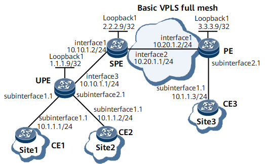
Networking Requirements
On the network shown in Figure 1, Site1, Site2, and Site3 belong to the same VPLS network; CE1 and CE2 access the basic full-mesh VPLS network through a UPE; CE3 accesses the network through a PE.

Configuration Notes
During the configuration, note that PEs on the same L2VPN must be configured with the same VSI ID.
Configuration Roadmap
The configuration roadmap is as follows:
Configure LDP VPLS between the SPE and PE. For configuration details, see Configuring LDP VPLS.
Establish an MPLS LDP peer relationship between the UPE and SPE.
Create a VSI on the SPE and specify the UPE as the lower-layer PE of the SPE.
Create a VSI on the UPE and specify the SPE as the VSI peer.
Configure CE1 and CE2 to access the UPE and configure CE3 to access the PE.
Data Preparation
To complete the configuration, you need the following data:
Names and IDs of VSIs
MPLS LSR IDs (as peer IP addresses) of UPEs, SPEs, and PEs
Routing protocol
Procedure
- Configure an IGP.
This example uses OSPF as the IGP. For configuration details, see Configuration Files in this section.
After completing the configurations, run the display ip routing-table command on the UPE, SPE, and PE. The command output shows that the UPE, SPE, and PE have learned each other's loopback interface address.
- Configure MPLS and MPLS LDP.
For configuration details, see Configuration Files in this section.
After completing the configurations, run the display mpls ldp session command on the UPE, SPE, and PE. The command output shows that the status of the peer relationship between the UPE and SPE or between the PE and SPE is Operational. Run the display mpls lsp command. The command output shows whether the LSP is set up.
- Enable MPLS L2VPN and configure a VSI.
# Configure the UPE.
<UPE> system-view
[~UPE] mpls l2vpn
[*UPE] vsi v123
[*UPE-vsi-v123] pwsignal ldp
[*UPE-vsi-v123-ldp] vsi-id 123
[*UPE-vsi-v123-ldp] peer 2.2.2.9
[*UPE-vsi-v123-ldp] commit
[*UPE-vsi-v123-ldp] quit
# Configure the SPE.
<SPE> system-view
[~SPE] mpls l2vpn
[*SPE] vsi v123
[*SPE-vsi-v123] pwsignal ldp
[*SPE-vsi-v123-ldp] vsi-id 123
[*SPE-vsi-v123-ldp] peer 3.3.3.9
[*SPE-vsi-v123-ldp] peer 1.1.1.9 upe
[*SPE-vsi-v123-ldp] commit
[*SPE-vsi-v123-ldp] quit
# Configure the PE.
<PE> system-view
[~PE] mpls l2vpn
[*PE] vsi v123
[*PE-vsi-v123] pwsignal ldp
[*PE-vsi-v123-ldp] vsi-id 123
[*PE-vsi-v123-ldp] peer 2.2.2.9
[*PE-vsi-v123-ldp] commit
[*PE-vsi-v123-ldp] quit
- Bind VSIs to AC interfaces on the SPE and UPE.
# Configure the UPE.
[~UPE] interface gigabitethernet0/1/0.1
[*UPE-GigabitEthernet0/1/0.1] shutdown
[*UPE-GigabitEthernet0/1/0.1] vlan-type dot1q 10
[*UPE-GigabitEthernet0/1/0.1] l2 binding vsi v123
[*UPE-GigabitEthernet0/1/0.1] undo shutdown
[*UPE-GigabitEthernet0/1/0.1] quit
[*UPE] interface gigabitethernet0/1/8.1
[*UPE-GigabitEthernet0/1/8.1] shutdown
[*UPE-GigabitEthernet0/1/8.1] vlan-type dot1q 10
[*UPE-GigabitEthernet0/1/8.1] l2 binding vsi v123
[*UPE-GigabitEthernet0/1/8.1] undo shutdown
[*UPE-GigabitEthernet0/1/8.1] commit
[*UPE-GigabitEthernet0/1/8.1] quit
# Configure the PE.
[~PE] interface gigabitethernet0/1/8.1
[*PE-GigabitEthernet0/1/8.1] shutdown
[*PE-GigabitEthernet0/1/8.1] vlan-type dot1q 10
[*PE-GigabitEthernet0/1/8.1] l2 binding vsi v123
[*PE-GigabitEthernet0/1/8.1] undo shutdown
[*PE-GigabitEthernet0/1/8.1] commit
[*PE-GigabitEthernet0/1/8.1] quit
- Verify the configuration.
After the preceding configurations, run the display vsi name v123 verbose command on the SPE. The command output shows that the status of the VSI named v123 is up, and the status of the corresponding PW is also up.
[~SPE] display vsi name v123 verbose
 ***VSI Name               : v123
    Administrator VSI      : no
    Isolate Spoken         : disable
    VSI Index              : 1
    PW Signaling           : ldp
    Member Discovery Style : --
    Bridge-domain Mode     : disable
    PW MAC Learning Style  : unqualify
    Encapsulation Type     : vlan
    MTU                    : 1500
    Diffserv Mode          : uniform
    Service Class          : --
    Color                  : --
    DomainId               : 255
    Domain Name            :
    Ignore AcState         : disable
    P2P VSI                : disable
    Create Time            : 0 days, 0 hours, 20 minutes, 49 seconds
    VSI State              : up
    Resource Status        : --

    VSI ID                 : 123
   *Peer Router ID         : 1.1.1.9
    primary or secondary   : primary
    ignore-standby-state   : no
    VC Label               : 19
    Peer Type              : dynamic
    Session                : up
    Tunnel ID              : 0x0000000001004c4b41
    Broadcast Tunnel ID    : --
    Broad BackupTunnel ID  : --
    CKey                   : 2
    NKey                   : 788529260
    Stp Enable             : 0
    PwIndex                : 2
    Control Word           : disable
   *Peer Router ID         : 3.3.3.9
    primary or secondary   : primary
    ignore-standby-state   : no
    VC Label               : 18
    Peer Type              : dynamic
    Session                : up
    Tunnel ID              : 0x0000000001004c4b42
    Broadcast Tunnel ID    : --
    Broad BackupTunnel ID  : --
    CKey                   : 1
    NKey                   : 788529259
    Stp Enable             : 0
    PwIndex                : 1
    Control Word           : disable

  **PW Information:

   *Peer Ip Address        : 1.1.1.9
    PW State               : up
    Local VC Label         : 19
    Remote VC Label        : 19
    Remote Control Word    : disable
    PW Type                : MEHVPLS
    Tunnel ID              : 0x0000000001004c4b41
    Broadcast Tunnel ID    : --
    Broad BackupTunnel ID  : --
    Ckey                   : 2
    Nkey                   : 788529260
    Main PW Token          : 0x0
    Slave PW Token         : 0x0
    Tnl Type               : ldp
    OutInterface           : LDP LSP
    Backup OutInterface    : --
    Stp Enable             : 0
    PW Last Up Time        : 2012/12/05 07:05:36
    PW Total Up Time       : 0 days, 0 hours, 18 minutes, 34 seconds
   *Peer Ip Address        : 3.3.3.9
    PW State               : up
    Local VC Label         : 18
    Remote VC Label        : 19
    Remote Control Word    : disable
    PW Type                : label
    Tunnel ID              : 0x0000000001004c4b42
    Broadcast Tunnel ID    : --
    Broad BackupTunnel ID  : --
    Ckey                   : 1
    Nkey                   : 788529259
    Main PW Token          : 0x0
    Slave PW Token         : 0x0
    Tnl Type               : ldp
    OutInterface           : LDP LSP
    Backup OutInterface    : --
    Stp Enable             : 0
    PW Last Up Time        : 2012/12/05 07:05:59
    PW Total Up Time       : 0 days, 0 hours, 18 minutes, 2 seconds
    PW Total Up Time       : 0 days, 11 hours, 16 minutes, 38 seconds
CE1, CE2, and CE3 can ping each other. After you run the shutdown command on GE 0/1/8.1 (to which the VSI is bound) of the UPE or the PE, CE2 and CE3 cannot ping each other. This means that user data is transmitted over the PW of this VSI.
Configuration Files
UPE configuration file
#
 sysname UPE
#
 mpls lsr-id 1.1.1.9
 mpls
#
 mpls l2vpn
#
vsi v123
 pwsignal ldp
  vsi-id 123
  peer 2.2.2.9
#
mpls ldp
#
 mpls ldp remote-peer 2.2.2.9
 remote-ip 2.2.2.9
#
interface GigabitEthernet0/1/0.1
 undo shutdown
 vlan-type dot1q 10
 l2 binding vsi v123
#
interface GigabitEthernet0/1/8.1
 undo shutdown
 vlan-type dot1q 10
 l2 binding vsi v123
#
interface GigabitEthernet0/1/16
 undo shutdown
 ip address 10.10.1.1 255.255.255.0
 mpls
 mpls ldp
#
interface LoopBack1
 ip address 1.1.1.9 255.255.255.255
#
ospf 1
 area 0.0.0.0
  network 1.1.1.9 0.0.0.0
  network 10.10.1.0 0.0.0.255
#
return
SPE configuration file
#
 sysname SPE
#
 mpls lsr-id 2.2.2.9
 mpls
#
 mpls l2vpn
#
vsi v123
 pwsignal ldp
  vsi-id 123
  peer 3.3.3.9
  peer 1.1.1.9 upe
#
mpls ldp
#
 mpls ldp remote-peer 1.1.1.9
 remote-ip 1.1.1.9
#
interface GigabitEthernet0/1/0
 undo shutdown
 ip address 10.10.1.2 255.255.255.0
 mpls
 mpls ldp
#
interface GigabitEthernet0/1/8
 undo shutdown
 ip address 10.20.1.1 255.255.255.0
 mpls
 mpls ldp
#
interface LoopBack1
 ip address 2.2.2.9 255.255.255.255
#
ospf 1
 area 0.0.0.0
  network 2.2.2.9 0.0.0.0
  network 10.20.1.0 0.0.0.255
  network 10.10.1.0 0.0.0.255
#
return
PE configuration file
#
 sysname PE
#
 mpls lsr-id 3.3.3.9
 mpls
#
 mpls l2vpn
#
vsi v123
 pwsignal ldp
  vsi-id 123
  peer 2.2.2.9
#
mpls ldp
#
interface GigabitEthernet0/1/8.1
 undo shutdown
 vlan-type dot1q 10
 l2 binding vsi v123
#
interface 1/0/0
 undo shutdown
 ip address 10.20.1.2 255.255.255.0
 mpls
 mpls ldp
#
interface LoopBack1
 ip address 3.3.3.9 255.255.255.255
#
ospf 1
 area 0.0.0.0
  network 10.20.1.0 0.0.0.255
  network 3.3.3.9 0.0.0.0
#
return
CE1 configuration file
#
 sysname CE1
#
interface GigabitEthernet0/1/0.1
 undo shutdown
 vlan-type dot1q 10
 ip address 10.1.1.1 255.255.255.0
#
return
CE2 configuration file
#
 sysname CE2
#
interface GigabitEthernet0/1/0.1
 undo shutdown
 vlan-type dot1q 10
 ip address 10.1.1.2 255.255.255.0
#
return
CE3 configuration file
#
 sysname CE3
#
interface GigabitEthernet0/1/0.1
 undo shutdown
 vlan-type dot1q 10
 ip address 10.1.1.3 255.255.255.0
#
return