Example for Configuring Dynamic VPWS Accessing VPLS
If UPEs do not support VPLS, you can configure VPWS accessing VPLS.
Networking Requirements
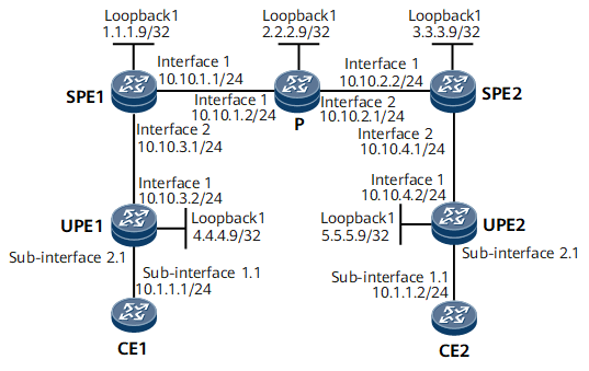
On the network shown in Figure 1, UPEs access SPEs over VPWS; CE1 and CE2 access a full-mesh VPLS network through UPEs.
Configuration Notes
When configuring dynamic VPWS accessing VPLS, note the following:
- PEs belonging to the same L2VPN must have the same VSI ID.
Configuration Roadmap
The configuration roadmap is as follows:
Configure LDP VPLS between SPEs.
Configure basic MPLS L2VPN functions on UPEs and SPEs.
Enable MAC Withdrawal for the VSI on each SPE.
Configure UPEs to access SPEs over VPWS.
Data Preparation
To complete the configuration, you need the following data:
VSI names and IDs
MPLS LSR IDs of UPEs and SPEs, which are used as peer IP addresses
Routing protocol
Procedure
- Configure IP addresses.
Configure an IP address and mask for each interface, including the loopback interface, according to Figure 1.

UPEs function as switching devices. If all the interfaces on UPEs are Layer 2 GE interfaces, you cannot directly configure IP addressed for the interfaces. Instead, you need to add the interfaces to a VLAN, and then configure IP addresses for the VLANIF interfaces. For details, see "VLAN Configuration" in NetEngine 8000 F Configuration Guide - LAN Access and MAN Access.
- Configure an IGP.
Configure OSPF on SPEs and P to advertise the network segment and the host routes of LSR IDs.
# Configure SPE1.
<SPE1> system-view
[~SPE1] ospf
[*SPE1-ospf-1] area 0
[*SPE1-ospf-1-area-0.0.0.0] network 1.1.1.9 0.0.0.0
[*SPE1-ospf-1-area-0.0.0.0] network 10.10.1.0 0.0.0.255
[*SPE1-ospf-1-area-0.0.0.0] network 10.10.3.0 0.0.0.255
[*SPE1-ospf-1-area-0.0.0.0] quit
[*SPE1-ospf-1] quit
[*SPE1] commit
# Configure the P.
<P> system-view
[~P] ospf
[*P-ospf-1] area 0
[*P-ospf-1-area-0.0.0.0] network 2.2.2.9 0.0.0.0
[*P-ospf-1-area-0.0.0.0] network 10.10.1.0 0.0.0.255
[*P-ospf-1-area-0.0.0.0] network 10.10.2.0 0.0.0.255
[*P-ospf-1-area-0.0.0.0] quit
[*P-ospf-1] quit
[*P] commit
# Configure SPE2.
<SPE2> system-view
[~SPE2] ospf
[*SPE2-ospf-1] area 0
[*SPE2-ospf-1-area-0.0.0.0] network 3.3.3.9 0.0.0.0
[*SPE2-ospf-1-area-0.0.0.0] network 10.10.2.0 0.0.0.255
[*SPE2-ospf-1-area-0.0.0.0] network 10.10.4.0 0.0.0.255
[*SPE2-ospf-1-area-0.0.0.0] quit
[*SPE2-ospf-1] quit
[*SPE2] commit
# Configure UPE1.
<UPE1> system-view
[~UPE1] ospf
[*UPE1-ospf-1] area 0
[*UPE1-ospf-1-area-0.0.0.0] network 4.4.4.9 0.0.0.0
[*UPE1-ospf-1-area-0.0.0.0] network 10.10.3.0 0.0.0.255
[*UPE1-ospf-1-area-0.0.0.0] quit
[*UPE1-ospf-1] quit
[*UPE1] commit
# Configure UPE2.
<UPE2> system-view
[~UPE2] ospf
[*UPE2-ospf-1] area 0
[*UPE2-ospf-1-area-0.0.0.0] network 5.5.5.9 0.0.0.0
[*UPE2-ospf-1-area-0.0.0.0] network 10.10.4.0 0.0.0.255
[*UPE2-ospf-1-area-0.0.0.0] quit
[*UPE2-ospf-1] quit
[*UPE2] commit
- Configure basic MPLS functions and LDP.
# Configure SPE1.
[~SPE1] mpls lsr-id 1.1.1.9
[*SPE1] mpls
[*SPE1-mpls] quit
[*SPE1] mpls ldp
[*SPE1-mpls-ldp] quit
[*SPE1] interface gigabitethernet 0/1/0
[*SPE1-GigabitEthernet0/1/0] mpls
[*SPE1-GigabitEthernet0/1/0] mpls ldp
[*SPE1-GigabitEthernet0/1/0] quit
[*SPE1-GigabitEthernet0/1/8] mpls
[*SPE1-GigabitEthernet0/1/8] mpls ldp
[*SPE1-GigabitEthernet0/1/8] quit
[*SPE1] commit
# Configure the P.
[~P] mpls lsr-id 2.2.2.9
[*P] mpls
[*P-mpls] quit
[*P] mpls ldp
[*P-mpls-ldp] quit
[*P] interface gigabitethernet 0/1/0
[*P-GigabitEthernet0/1/0] mpls
[*P-GigabitEthernet0/1/0] mpls ldp
[*P-GigabitEthernet0/1/0] quit
[*P] interface gigabitethernet 0/1/8
[*P-GigabitEthernet0/1/8] mpls
[*P-GigabitEthernet0/1/8] mpls ldp
[*P-GigabitEthernet0/1/8] quit
[*P] commit
# Configure SPE2.
[~SPE2] mpls lsr-id 3.3.3.9
[*SPE2] mpls
[*SPE2-mpls] quit
[*SPE2] mpls ldp
[*SPE2-mpls-ldp] quit
[*SPE2] interface gigabitethernet 0/1/0
[*SPE2-GigabitEthernet0/1/0] mpls
[*SPE2-GigabitEthernet0/1/0] mpls ldp
[*SPE2-GigabitEthernet0/1/0] quit
[*SPE2-GigabitEthernet0/1/8] mpls
[*SPE2-GigabitEthernet0/1/8] mpls ldp
[*SPE2-GigabitEthernet0/1/8] quit
[*SPE2] commit
# Configure UPE1.
[~UPE1] mpls lsr-id 4.4.4.9
[*UPE1] mpls
[*UPE1-mpls] quit
[*UPE1] mpls ldp
[*UPE1-mpls-ldp] quit
[*UPE1] interface gigabitethernet 0/1/0
[*UPE1-GigabitEthernet0/1/0] mpls
[*UPE1-GigabitEthernet0/1/0] mpls ldp
[*UPE1-GigabitEthernet0/1/0] quit
[*UPE1] commit
# Configure UPE2.
[~UPE2] mpls lsr-id 5.5.5.9
[*UPE2] mpls
[*UPE2-mpls] quit
[*UPE2] mpls ldp
[*UPE2-mpls-ldp] quit
[*UPE2] interface gigabitethernet 0/1/0
[*UPE2-GigabitEthernet0/1/0] mpls
[*UPE2-GigabitEthernet0/1/0] mpls ldp
[*UPE2-GigabitEthernet0/1/0] quit
[~UPE2] commit
After completing the configuration, run the display mpls ldp session command on SPE1, P, and SPE2. The status of the peer relationship between SPE1 and P or between SPE2 and P is Operational, which indicates that the peer relationship has been established. Run the display mpls lsp command to view information about MPLS LSP establishment.
The information displayed on SPE1 is used as an example.
<SPE1> display mpls ldp session
LDP Session(s) in Public Network
Codes: LAM(Label Advertisement Mode), SsnAge Unit(DDDD:HH:MM)
 An asterisk (*) before a session means the session is being deleted.
 ------------------------------------------------------------------------------
 PeerID            Status      LAM  SsnRole  SsnAge      KASent/Rcv
 ------------------------------------------------------------------------------
 2.2.2.9:0          Operational DU   Passive  000:00:01   7/7
 ------------------------------------------------------------------------------
 TOTAL: 1 session(s) Found.
<SPE1> display mpls lsp
Flag after Out IF: (I) - RLFA Iterated LSP, (I*) - Normal and RLFA Iterated LSP
Flag after LDP FRR: (L) - Logic FRR LSP
----------------------------------------------------------------------
                 LSP Information: LDP LSP
----------------------------------------------------------------------
FEC                In/Out Label  In/Out IF                      Vrf Name
2.2.2.9/32         NULL/3        -/GigabitEthernet0/1/0
1.1.1.9/32         3/NULL        -/-
3.3.3.9/32         NULL/1025     -/GigabitEthernet0/1/0
- Establish a remote LDP session between SPEs.
# Configure SPE1.
[~SPE1] mpls ldp remote-peer 3.3.3.9
[*SPE1-mpls-ldp-remote-3.3.3.9] remote-ip 3.3.3.9
[*SPE1-mpls-ldp-remote-3.3.3.9] quit
[*SPE1] commit
# Configure SPE2.
[~SPE2] mpls ldp remote-peer 1.1.1.9
[*SPE2-mpls-ldp-remote-1.1.1.9] remote-ip 1.1.1.9
[*SPE2-mpls-ldp-remote-1.1.1.9] quit
[*SPE2] commit
After completing the configuration, run the display mpls ldp session command on SPE1 and SPE2. The status of the peer relationship between SPE1 and SPE2 is Operational, which indicates that the peer relationship has been established.
The information displayed on SPE1 is used as an example.
<SPE1> display mpls ldp session LDP Session(s) in Public Network Codes: LAM(Label Advertisement Mode), SsnAge Unit(DDDD:HH:MM) An asterisk (*) before a session means the session is being deleted. ------------------------------------------------------------------------------ PeerID Status LAM SsnRole SsnAge KASent/Rcv ------------------------------------------------------------------------------ 2.2.2.9:0 Operational DU Passive 000:00:05 24/24 3.3.3.9:0 Operational DU Passive 000:00:01 5/5 ------------------------------------------------------------------------------ TOTAL: 2 session(s) Found. - Enable MPLS L2VPN on UPEs and configure UPEs to access SPEs over VPWS.
# Configure UPE1.
<UPE1> system-view
[~UPE1] mpls l2vpn
[*UPE1-l2vpn] quit
[*UPE1] interface gigabitethernet 0/1/8.1
[*UPE1-GigabitEthernet0/1/8.1] shutdown
[*UPE1-GigabitEthernet0/1/8.1] vlan-type dot1q 1
[*UPE1-GigabitEthernet0/1/8.1] mpls l2vc 1.1.1.9 100
[*UPE1-GigabitEthernet0/1/8.1] undo shutdown
[*UPE1-GigabitEthernet0/1/8.1] quit
[*UPE1] commit
# Configure UPE2.
<UPE2> system-view
[~UPE2] mpls l2vpn
[*UPE2-l2vpn] quit
[*UPE2] interface gigabitethernet 0/1/8.1
[*UPE2-GigabitEthernet0/1/8.1] shutdown
[*UPE2-GigabitEthernet0/1/8.1] vlan-type dot1q 1
[*UPE2-GigabitEthernet0/1/8.1] mpls l2vc 3.3.3.9 100
[*UPE2-GigabitEthernet0/1/8.1] undo shutdown
[*UPE2-GigabitEthernet0/1/8.1] quit
[*UPE2] commit
- Enable MPLS L2VPN on SPEs
# Configure SPE1.
<SPE1> system-view
[~SPE1] mpls l2vpn
[*SPE1] vsi v100
[*SPE1-vsi-v100] pwsignal ldp
[*SPE1-vsi-v100-ldp] vsi-id 100
[*SPE1-vsi-v100-ldp] mac-withdraw enable
[*SPE1-vsi-v100-ldp] peer 3.3.3.9
[*SPE1-vsi-v100-ldp] peer 4.4.4.9 upe
[*SPE1-vsi-v100-ldp] quit
[*SPE1-vsi-v100] quit
[*SPE1] commit
# Configure SPE2.
<SPE2> system-view
[~SPE2] mpls l2vpn
[*SPE2] vsi v100
[*SPE2-vsi-v100] pwsignal ldp
[*SPE2-vsi-v100-ldp] vsi-id 100
[*SPE2-vsi-v100-ldp] mac-withdraw enable
[*SPE2-vsi-v100-ldp] peer 1.1.1.9
[*SPE2-vsi-v100-ldp] peer 5.5.5.9 upe
[*SPE2-vsi-v100-ldp] quit
[*SPE2-vsi-v100] quit
[*SPE2] commit
- Verify the configuration.
After completing the configurations, run the display mpls l2vc command on UPEs. The command output shows that a PW has been established and VC state is up. The following example uses the command output on UPE1.
<UPE1> display mpls l2vc interface gigabitethernet 0/1/8.1
*client interface       : GigabitEthernet0/1/8.1 is up
 Administrator PW       : no
 session state          : up
 AC status              : up
 VC state               : up
 Label state            : 0
 Token state            : 0
 VC ID                  : 100
 VC type                : VLAN
 destination            : 1.1.1.9
 local group ID         : 0         remote group ID      : 0
 local VC label         : 23        remote VC label      : 24
 local AC OAM State     : up
 local PSN OAM State    : up
 local forwarding state : forwarding
 local status code      : 0x0 (forwarding)
 remote AC OAM State    : up
 remote PSN OAM state   : up
 remote forwarding state: forwarding
 remote status code     : 0x0 (forwarding)
 ignore standby state   : no
 BFD for PW             : unavailable
 VCCV State             : --
 manual fault           : not set
 active state           : active
 forwarding entry       : exist
 OAM Protocol           : --
 OAM Status             : --
 OAM Fault Type         : --
 PW APS ID              : --
 PW APS Status          : --
 TTL Value              : 1
 link state             : up
 local VC MTU           : 1500      remote VC MTU        : 1500
 local VCCV             : alert ttl lsp-ping bfd
 remote VCCV            : alert lsp-ping
 local control word     : disable   remote control word  : disable
 tunnel policy name     : --
 PW template name       : --
 primary or secondary   : primary
 load balance type      : flow
 Access-port            : false
 Switchover Flag        : false
 VC tunnel info         : 1 tunnels
    NO.0 TNL type       : ldp, TNL ID : 0x0000000001004c4b61
 create time            : 0 days, 0 hours, 19 minutes, 17 seconds
 up time                : 0 days, 0 hours, 14 minutes, 34 seconds
 last change time       : 0 days, 0 hours, 14 minutes, 34 seconds
 VC last up time        : 2012/12/05 08:13:31
 VC total up time       : 0 days, 0 hours, 14 minutes, 34 seconds
 CKey                   : 65
 NKey                   : 1493172339
 PW redundancy mode     : frr
 AdminPw interface      : --
 AdminPw link state     : --
 Forward state          : send inactive, receive inactive
 Diffserv Mode          : uniform
 Service Class          : --
 Color                  : --
 DomainId               : --
 Domain Name            : --
Run the display vsi name v100 verbose command on SPEs. The command output shows that the VSI named v100 is up and the corresponding PW is also up. The information displayed on SPE1 is used as an example.
<SPE1> display vsi name v100 verbose
 ***VSI Name               : v100
    Administrator VSI      : no
    Isolate Spoken         : disable
    VSI Index              : 2
    PW Signaling           : ldp
    Member Discovery Style : --
    Bridge-domain Mode     : disable
    PW MAC Learning Style  : unqualify
    Encapsulation Type     : vlan
    MTU                    : 1500
    Diffserv Mode          : uniform
    Service Class          : --
    Color                  : --
    DomainId               : 255
    Domain Name            :
    Ignore AcState         : disable
    P2P VSI                : disable
    Create Time            : 0 days, 0 hours, 4 minutes, 8 seconds
    VSI State              : up
    Resource Status        : --

    VSI ID                 : 100
   *Peer Router ID         : 3.3.3.9
    primary or secondary   : primary
    ignore-standby-state   : no
    VC Label               : 23
    Peer Type              : dynamic
    Session                : up
    Tunnel ID              : 0x0000000001004c4b62
    Broadcast Tunnel ID    : --
    Broad BackupTunnel ID  : --
    CKey                   : 33
    NKey                   : 788529266
    Stp Enable             : 0
    PwIndex                : 33
    Control Word           : disable
   *Peer Router ID         : 4.4.4.9
    primary or secondary   : primary
    ignore-standby-state   : no
    VC Label               : 24
    Peer Type              : dynamic
    Session                : up
    Tunnel ID              : 0x0000000001004c4b63
    Broadcast Tunnel ID    : --
    Broad BackupTunnel ID  : --
    CKey                   : 34
    NKey                   : 788529267
    Stp Enable             : 0
    PwIndex                : 34
    Control Word           : disable

  **PW Information:

   *Peer Ip Address        : 3.3.3.9
    PW State               : up
    Local VC Label         : 23
    Remote VC Label        : 19
    Remote Control Word    : disable
    PW Type                : label
    Tunnel ID              : 0x0000000001004c4b62
    Broadcast Tunnel ID    : --
    Broad BackupTunnel ID  : --
    Ckey                   : 33
    Nkey                   : 788529266
    Main PW Token          : 0x0
    Slave PW Token         : 0x0
    Tnl Type               : ldp
    OutInterface           : LDP LSP
    Backup OutInterface    : --
    Stp Enable             : 0
    PW Last Up Time        : 2012/12/05 08:14:03
    PW Total Up Time       : 0 days, 0 hours, 2 minutes, 20 seconds
   *Peer Ip Address        : 4.4.4.9
    PW State               : up
    Local VC Label         : 24
    Remote VC Label        : 23
    Remote Control Word    : disable
    PW Type                : MEHVPLS
    Tunnel ID              : 0x0000000001004c4b63
    Broadcast Tunnel ID    : --
    Broad BackupTunnel ID  : --
    Ckey                   : 34
    Nkey                   : 788529267
    Main PW Token          : 0x0
    Slave PW Token         : 0x0
    Tnl Type               : ldp
    OutInterface           : LDP LSP
    Backup OutInterface    : --
    Stp Enable             : 0
    PW Last Up Time        : 2012/12/05 08:13:30
    PW Total Up Time       : 0 days, 0 hours, 3 minutes, 7 seconds
CE1 and CE2, which reside on the same network segment, can ping each other. After the shutdown command is run on GE 0/1/8.1 that is bound to the VSI on the UPE or PE, CE1 and CE2 cannot ping each other. This indicates that service data is transmitted through the PW of the VSI.
Before GE 0/1/8 on SPE1 is shut down, check the MAC address table learned by the VSI on SPE2.
<SPE2> display mac-address dynamic
MAC address table of slot 1:
-------------------------------------------------------------------------------
MAC Address    VLAN/BD/    PEVLAN CEVLAN Port                        Type      LSP/LSR-ID
               VSI/SI/EVPN                                                     MAC-Tunnel
-------------------------------------------------------------------------------
00e0-fc00-1234 V100        -      -      GigabitEthernet0/1/8        dynamic   10/51
00e0-fc00-3456 V100        -      -      GigabitEthernet0/1/0        dynamic   10/49
-------------------------------------------------------------------------------
Total matching items on slot 1 displayed = 2
After GE 0/1/8 on SPE1 is shut down, the VSI becomes down. Check the MAC address table learned by the VSI on SPE2, and you can find that the MAC address learned by GE 0/1/8 is deleted.
Configuration Files
CE1 configuration file
#
 sysname CE1
#
interface GigabitEthernet0/1/0
 undo shutdown
#
interface GigabitEthernet0/1/0.1
 undo shutdown
 vlan-type dot1q 1
 ip address 10.1.1.1 255.255.255.0
#
return
CE2 configuration file
#
 sysname CE2
#
interface GigabitEthernet0/1/0
 undo shutdown
#
interface GigabitEthernet0/1/0.1
 undo shutdown
 vlan-type dot1q 1
 ip address 10.1.1.2 255.255.255.0
#
return
UPE1 configuration file
#
 sysname UPE1
#
 mpls lsr-id 4.4.4.9
 mpls
#
 mpls l2vpn
#
mpls ldp
#
interface GigabitEthernet0/1/0
 undo shutdown
 ip address 10.10.3.2 255.255.255.0
 mpls
 mpls ldp
#
interface GigabitEthernet0/1/8
 undo shutdown
#
interface GigabitEthernet0/1/8.1
 undo shutdown
 vlan-type dot1q 1
 mpls l2vc 1.1.1.9 100
#
interface LoopBack1
 ip address 4.4.4.9 255.255.255.255
#
ospf 1
 area 0.0.0.0
  network 4.4.4.9 0.0.0.0
  network 10.10.3.0 0.0.0.255
#
return
SPE1 configuration file
#
 sysname SPE1
#
 mpls lsr-id 1.1.1.9
 mpls
#
 mpls l2vpn
#
vsi v100
 pwsignal ldp
  vsi-id 100
  peer 3.3.3.9
  peer 4.4.4.9 upe
#
mpls ldp
#
 mpls ldp remote-peer 3.3.3.9
 remote-ip 3.3.3.9
#
interface GigabitEthernet0/1/0
 undo shutdown
 ip address 10.10.1.1 255.255.255.0
 mpls
 mpls ldp
#
interface GigabitEthernet0/1/8
 undo shutdown
 ip address 10.10.3.1 255.255.255.0
 mpls
 mpls ldp
#
interface LoopBack1
 ip address 1.1.1.9 255.255.255.255
#
ospf 1
 area 0.0.0.0
  network 1.1.1.9 0.0.0.0
  network 10.10.1.0 0.0.0.255
  network 10.10.3.0 0.0.0.255
#
return
P configuration file
#
 sysname P
#
 mpls lsr-id 2.2.2.9
 mpls
#
mpls ldp
#
interface GigabitEthernet0/1/0
 undo shutdown
 ip address 10.10.1.2 255.255.255.0
 mpls
 mpls ldp
#
interface GigabitEthernet0/1/8
 undo shutdown
 ip address 10.10.2.1 255.255.255.0
 mpls
 mpls ldp
#
interface LoopBack1
 ip address 2.2.2.9 255.255.255.255
#
ospf 1
 area 0.0.0.0
  network 2.2.2.9 0.0.0.0
  network 10.10.1.0 0.0.0.255
  network 10.10.2.0 0.0.0.255
#
return
SPE2 configuration file
#
 sysname SPE2
#
 mpls lsr-id 3.3.3.9
 mpls
#
 mpls l2vpn
#
vsi v100
 pwsignal ldp
  vsi-id 100
  peer 1.1.1.9
  peer 5.5.5.9 upe
#
mpls ldp
#
 mpls ldp remote-peer 1.1.1.9
 remote-ip 1.1.1.9
#
interface GigabitEthernet0/1/0
 undo shutdown
 ip address 10.10.2.2 255.255.255.0
 mpls
 mpls ldp
#
interface GigabitEthernet0/1/8
 undo shutdown
 ip address 10.10.4.1 255.255.255.0
 mpls
 mpls ldp
#
interface LoopBack1
 ip address 3.3.3.9 255.255.255.255
#
ospf 1
 area 0.0.0.0
  network 3.3.3.9 0.0.0.0
  network 10.10.2.0 0.0.0.255
  network 10.10.4.0 0.0.0.255
#
return
UPE2 configuration file
#
 sysname UPE2
#
 mpls lsr-id 5.5.5.9
 mpls
#
 mpls l2vpn
#
mpls ldp
#
interface GigabitEthernet0/1/0
 undo shutdown
 ip address 10.10.4.2 255.255.255.0
 mpls
 mpls ldp
#
interface GigabitEthernet0/1/8
 undo shutdown
#
interface GigabitEthernet0/1/8.1
 undo shutdown
 vlan-type dot1q 1
 mpls l2vc 3.3.3.9 100
#
interface LoopBack1
 ip address 5.5.5.9 255.255.255.255
#
ospf 1
 area 0.0.0.0
  network 5.5.5.9 0.0.0.0
  network 10.10.4.0 0.0.0.255
#
return