Example for Configuring Loop Detection on the VPLS Access Side (CE Dual-Homing)
In CE dual-homing networking, a CE is dual-homed to PE1 and PE2 through a switch, and PE1, PE2, and the switch constitute a ring network physically. In this case, you can enable loop detection on AC interfaces of PE1 and PE2 and specify blocking priorities for the interfaces on the active and standby links, which helps the devices break loops and prevent subsequent broadcast storms.
Networking Requirements
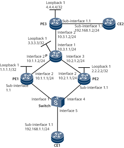
As shown in Figure 1, CE1 is dual-homed to PE1 and PE2 through Switch, and CE2 is directly connected to PE3. The CEs belong to the same VPLS network. VPLS PWs are established using the Label Distribution Protocol (LDP) as a VPLS signaling protocol, implementing communication between the CEs. Loop detection needs to be configured on PE1 and PE2 to prevent broadcast storms caused by loops formed by PE1, PE2, and Switch. The link between Switch and PE1 is the active link; the link between Switch and PE2 is the standby link and is blocked. If the active link fails and no loop is detected on the standby link within the configured period of 10 seconds, the standby link takes over traffic.

In this example, interface 1, interface 2, interface 3, interface 4, interface 5, and sub-interface 1.1 represent GE 0/1/0, GE 0/1/8, GE 0/1/16, GE 0/1/1, GE 0/1/2, and GE 0/1/0.1, respectively.
Configuration Roadmap
The configuration roadmap is as follows:
- Configure a routing protocol on the backbone network to implement connectivity between devices.
- Establish remote LDP sessions between PEs.
- Enable MPLS L2VPN on PEs.
- Create a VSI, specify LDP as a signaling protocol, and bind an AC interface to the VSI on each PE.
- Configure loop detection on AC interfaces of PEs.
Data Preparation
To complete the configuration, you need the following data:
- VSI name and ID
- Peer IP addresses and type of tunnel used for setting up peer relationships
- Names of interfaces bound to the VSI
- Loop detection priority and detection interval for unblocking an interface
Procedure
- Configure IP addresses.
Assign an IP address to each physical interface and loopback interface according to Figure 1.
For configuration details, see Configuration Files in this section.
- Configure an IGP (OSPF in this example) on the MPLS backbone network.
Ensure that the 32-bit loopback addresses of PEs and the P can be advertised through OSPF.
For configuration details, see Configuration Files in this section.
- Configure basic MPLS functions and LDP.
# Configure PE1.
<HUAWEI> system-view
[~HUAWEI] sysname PE1
[*PE1] mpls lsr-id 1.1.1.1
[*PE1] mpls
[*PE1-mpls] quit
[*PE1] mpls ldp
[*PE1-mpls-ldp] quit
[*PE1] interface GigabitEthernet 0/1/8
[*PE1-GigabitEthernet0/1/8] mpls
[*PE1-GigabitEthernet0/1/8] mpls ldp
[*PE1-GigabitEthernet0/1/8] undo shutdown
[*PE1-GigabitEthernet0/1/8] quit
# Configure PE2.
<HUAWEI> system-view
[~HUAWEI] sysname PE2
[*PE2] mpls lsr-id 2.2.2.2
[*PE2] mpls
[*PE2-mpls] quit
[*PE2] mpls ldp
[*PE2-mpls-ldp] quit
[*PE2] interface GigabitEthernet 0/1/8
[*PE2-GigabitEthernet0/1/8] mpls
[*PE2-GigabitEthernet0/1/8] mpls ldp
[*PE2-GigabitEthernet0/1/8] undo shutdown
[*PE2-GigabitEthernet0/1/8] quit
# Configure the P.
<HUAWEI> system-view
[~HUAWEI] sysname P
[*P] mpls lsr-id 3.3.3.3
[*P] mpls
[*P-mpls] quit
[*P] mpls ldp
[*P-mpls-ldp] quit
[*P] interface GigabitEthernet 0/1/0
[*P-GigabitEthernet0/1/0] mpls
[*P-GigabitEthernet0/1/0] mpls ldp
[*P-GigabitEthernet0/1/0] undo shutdown
[*P-GigabitEthernet0/1/0] quit
[*P] interface GigabitEthernet 0/1/8
[*P-GigabitEthernet0/1/8] mpls
[*P-GigabitEthernet0/1/8] mpls ldp
[*P-GigabitEthernet0/1/8] undo shutdown
[*P-GigabitEthernet0/1/8] quit
[*P] interface GigabitEthernet 0/1/16
[*P-GigabitEthernet0/1/16] mpls
[*P-GigabitEthernet0/1/16] mpls ldp
[*P-GigabitEthernet0/1/16] undo shutdown
[*P-GigabitEthernet0/1/16] quit
# Configure PE3.
<HUAWEI> system-view
[~HUAWEI] sysname PE3
[*PE3] mpls lsr-id 4.4.4.4
[*PE3] mpls
[*PE3-mpls] quit
[*PE3] mpls ldp
[*PE3-mpls-ldp] quit
[*PE3] interface GigabitEthernet 0/1/8
[*PE3-GigabitEthernet0/1/8] mpls
[*PE3-GigabitEthernet0/1/8] mpls ldp
[*PE3-GigabitEthernet0/1/8] undo shutdown
[*PE3-GigabitEthernet0/1/8] quit
- Establish remote LDP sessions between PEs.
# Configure PE1.
[~PE1] mpls ldp remote-peer pe2
[*PE1-mpls-ldp-remote-pe2] remote-ip 2.2.2.2
[*PE1-mpls-ldp-remote-pe2] quit
[*PE1] mpls ldp remote-peer pe3
[*PE1-mpls-ldp-remote-pe3] remote-ip 4.4.4.4
[*PE1-mpls-ldp-remote-pe3] quit
# Configure PE2.
[~PE2] mpls ldp remote-peer pe1
[*PE2-mpls-ldp-remote-pe1] remote-ip 1.1.1.1
[*PE2-mpls-ldp-remote-pe1] quit
[*PE2] mpls ldp remote-peer pe3
[*PE2-mpls-ldp-remote-pe3] remote-ip 4.4.4.4
[*PE2-mpls-ldp-remote-pe3] quit
# Configure PE3.
[~PE3] mpls ldp remote-peer pe1
[*PE3-mpls-ldp-remote-pe1] remote-ip 1.1.1.1
[*PE3-mpls-ldp-remote-pe1] quit
[*PE3] mpls ldp remote-peer pe2
[*PE3-mpls-ldp-remote-pe2] remote-ip 2.2.2.2
[*PE3-mpls-ldp-remote-pe2] quit
- Enable MPLS L2VPN on PEs.
# Configure PE1.
[~PE1] mpls l2vpn
[*PE1-l2vpn] quit
# Configure PE2.
[~PE2] mpls l2vpn
[*PE2-l2vpn] quit
- Create a VSI on each PE, specify LDP as a signaling protocol, and bind AC interfaces to the VSI.
# Configure PE1.
[~PE1] vsi a2 static
[*PE1-vsi-a2] pwsignal ldp
[*PE1-vsi-a2-ldp] vsi-id 2
[*PE1-vsi-a2-ldp] peer 2.2.2.2
[*PE1-vsi-a2-ldp] peer 4.4.4.4
[*PE1-vsi-a2-ldp] mac-withdraw enable
[*PE1-vsi-a2-ldp] interface-status-change mac-withdraw enable
[*PE1-vsi-a2-ldp] quit
[*PE1-vsi-a2] quit
[*PE1] interface gigabitethernet 0/1/0.1
[*PE1-GigabitEthernet0/1/0.1] shutdown
[*PE1-GigabitEthernet0/1/0.1] vlan-type dot1q 10
[*PE1-GigabitEthernet0/1/0.1] l2 binding vsi a2
[*PE1-GigabitEthernet0/1/0.1] undo shutdown
[*PE1-GigabitEthernet0/1/0.1] quit
# Configure PE2.
[~PE2] vsi a2 static
[*PE2-vsi-a2] pwsignal ldp
[*PE2-vsi-a2-ldp] vsi-id 2
[*PE2-vsi-a2-ldp] peer 1.1.1.1
[*PE2-vsi-a2-ldp] peer 4.4.4.4
[*PE2-vsi-a2-ldp] mac-withdraw enable
[*PE2-vsi-a2-ldp] interface-status-change mac-withdraw enable
[*PE2-vsi-a2-ldp] quit
[*PE2-vsi-a2] quit
[*PE2] interface gigabitethernet 0/1/0.1
[*PE2-GigabitEthernet0/1/0.1] shutdown
[*PE2-GigabitEthernet0/1/0.1] vlan-type dot1q 10
[*PE2-GigabitEthernet0/1/0.1] l2 binding vsi a2
[*PE2-GigabitEthernet0/1/0.1] undo shutdown
[*PE2-GigabitEthernet0/1/0.1] quit
# Configure PE3.
[~PE3] mpls l2vpn
[*PE3-l2vpn] quit
[*PE3] vsi a2 static
[*PE3-vsi-a2] pwsignal ldp
[*PE3-vsi-a2-ldp] vsi-id 2
[*PE3-vsi-a2-ldp] peer 1.1.1.1
[*PE3-vsi-a2-ldp] peer 2.2.2.2
[*PE3-vsi-a2-ldp] mac-withdraw enable
[*PE3-vsi-a2-ldp] interface-status-change mac-withdraw enable
[*PE3-vsi-a2-ldp] quit
[*PE3-vsi-a2] quit
[*PE3] interface gigabitethernet 0/1/0.1
[*PE3-GigabitEthernet0/1/0.1] shutdown
[*PE3-GigabitEthernet0/1/0.1] vlan-type dot1q 10
[*PE3-GigabitEthernet0/1/0.1] l2 binding vsi a2
[*PE3-GigabitEthernet0/1/0.1] undo shutdown
[*PE3-GigabitEthernet0/1/0.1] quit
After the configuration is complete, check VSI connection information on a PE. You can view that two PWs have been successfully established.
The following example uses the command output on PE1.[~PE1] display vsi name a2 verbose ***VSI Name : a2 Administrator VSI : no Isolate Spoken : disable VSI Index : 0 PW Signaling : ldp Member Discovery Style : static PW MAC Learn Style : unqualify Encapsulation Type : vlan MTU : 1500 Diffserv Mode : uniform Service Class : -- Color : -- DomainId : 255 Domain Name : Create Time : 1 days, 15 hours, 11 minutes, 4 seconds VSI State : up VSI ID : 2 *Peer Router ID : 2.2.2.2 VC Label : 23552 Peer Type : dynamic Session : up Tunnel ID : 0x1002000, *Peer Router ID : 4.4.4.4 VC Label : 23553 Peer Type : dynamic Session : up Tunnel ID : 0x1002002, Interface Name : GigabitEthernet0/1/0.1 State : up Last Up Time : 2020/10/27 18:10:44 Total Up Time : 1 days, 16 hours, 53 minutes, 33 seconds **PW Information: *Peer Ip Address : 2.2.2.2 PW State : up Local VC Label : 23552 Remote VC Label : 23552 PW Type : label Tunnel ID : 0x1002000 *Peer Ip Address : 4.4.4.4 PW State : up Local VC Label : 23553 Remote VC Label : 23552 PW Type : label Tunnel ID : 0x1002002 FIB Link-ID : 1 PW Last Up Time : 2020/10/28 10:03:35 PW Total Up Time : 0 days, 11 hours, 15 minutes, 38 seconds
- Configure CEs to access the VPLS network.
# Configure Switch.
Create VLAN 10 on Switch and add GE 0/1/0, GE 0/1/1, and GE 0/1/2 to VLAN 10.
<HUAWEI> system-view
[~HUAWEI] sysname Switch
[*Switch] vlan 10
[*Switch-vlan10] quit
[*Switch] interface gigabitethernet 0/1/0
[*Switch-GigabitEthernet0/1/0] port trunk allow-pass vlan 10
[*Switch-GigabitEthernet0/1/0] quit
[*Switch] interface gigabitethernet 0/1/1
[*Switch-GigabitEthernet0/1/1] port trunk allow-pass vlan 10
[*Switch-GigabitEthernet0/1/1] quit
[*Switch] interface gigabitethernet 0/1/2
[*Switch-GigabitEthernet0/1/2] port trunk allow-pass vlan 10
[*Switch-GigabitEthernet0/1/2] quit
# Configure CE1.
<HUAWEI> system-view
[~HUAWEI] sysname CE1
[*CE1] interface gigabitethernet 0/1/0.1
[*CE1-GigabitEthernet0/1/0.1] vlan-type dot1q 10
[*CE1-GigabitEthernet0/1/0.1] ip address 192.168.1.1 24
[*CE1-GigabitEthernet0/1/0.1] quit
# Configure CE2.
<HUAWEI> system-view
[~HUAWEI] sysname CE2
[*CE2] interface gigabitethernet 0/1/0.1
[*CE2-GigabitEthernet0/1/0.1] vlan-type dot1q 10
[*CE2-GigabitEthernet0/1/0.1] ip address 192.168.1.2 24
[*CE2-GigabitEthernet0/1/0.1] quit
- Configure loop detection on PEs.
# Configure PE1.
[~PE1] loop-detection enable
[*PE1] interface gigabitethernet0/1/0.1
[*PE1-GigabitEthernet0/1/0.1] loop-detect enable
[*PE1-GigabitEthernet0/1/0.1] loop-detect block 10
[*PE1-GigabitEthernet0/1/0.1] loop-detect priority 2
[*PE1-GigabitEthernet0/1/0.1] loop-detect trigger interface-down enable
[*PE1-GigabitEthernet0/1/0.1] quit
# Configure PE2.
[~PE2] loop-detection enable
[*PE2] interface gigabitethernet0/1/0.1
[*PE2-GigabitEthernet0/1/0.1] loop-detect enable
[*PE2-GigabitEthernet0/1/0.1] loop-detect block 10
[*PE2-GigabitEthernet0/1/0.1] loop-detect priority 1
[*PE2-GigabitEthernet0/1/0.1] loop-detect trigger interface-down enable
[*PE2-GigabitEthernet0/1/0.1] quit
- Verify the configuration.
After completing the configuration, run the display loop-detect block all command on PE1 and PE2. The command output shows that GE 0/1/0.1 on PE2 is already blocked.
[~PE1] display loop-detect block all
Info: There is no block interface in this router.
[~PE2] display loop-detect block all
Info: GigabitEthernet0/1/0.1 has been blocked.
CE1 (192.168.1.1) can ping CE2 (192.168.1.2).
[~CE1] ping 192.168.1.2
PING 192.168.1.2: 56  data bytes, press CTRL_C to break
    Reply from 192.168.1.2: bytes=56 Sequence=1 ttl=255 time=90 ms
    Reply from 192.168.1.2: bytes=56 Sequence=2 ttl=255 time=77 ms
    Reply from 192.168.1.2: bytes=56 Sequence=3 ttl=255 time=34 ms
    Reply from 192.168.1.2: bytes=56 Sequence=4 ttl=255 time=46 ms
    Reply from 192.168.1.2: bytes=56 Sequence=5 ttl=255 time=94 ms
  --- 192.168.1.2 ping statistics ---
    5 packet(s) transmitted
    5 packet(s) received
    0.00% packet loss
    round-trip min/avg/max = 34/68/94 ms
Configuration Files
PE1 configuration file
#
 sysname PE1
#
 mpls lsr-id 1.1.1.1
 mpls
#
 mpls l2vpn
#
vsi a2 static
 pwsignal ldp
  vsi-id 2
  peer 2.2.2.2
  peer 4.4.4.4
  mac-withdraw enable
  interface-status-change mac-withdraw enable
#
mpls ldp
#
mpls ldp remote-peer pe2
 remote-ip 2.2.2.2
#
mpls ldp remote-peer pe3
 remote-ip 4.4.4.4
#
interface GigabitEthernet0/1/0
 undo shutdown
#
interface GigabitEthernet0/1/0.1
 vlan-type dot1q 10
 l2 binding vsi a2
 loop-detect enable
 loop-detect block 10
 loop-detect priority 2
 loop-detect trigger interface-down enable
#
interface GigabitEthernet0/1/8
 undo shutdown
 ip address 10.1.1.1 255.255.255.0
 mpls
 mpls ldp
#
interface LoopBack1
 ip address 1.1.1.1 255.255.255.255
#
ospf 1
 area 0.0.0.0
  network 1.1.1.1 0.0.0.0
  network 10.1.1.0 0.0.0.255
#
return
PE2 configuration file
#
 sysname PE2
#
 mpls lsr-id 2.2.2.2
 mpls
#
 mpls l2vpn
#
vsi a2 static
 pwsignal ldp
  vsi-id 2
  peer 1.1.1.1
  peer 4.4.4.4
  mac-withdraw enable
  interface-status-change mac-withdraw enable
#
mpls ldp
#
mpls ldp remote-peer pe1
 remote-ip 1.1.1.1
#
mpls ldp remote-peer pe3
 remote-ip 4.4.4.4
#
interface GigabitEthernet0/1/0
 undo shutdown
#
interface GigabitEthernet0/1/0.1
 vlan-type dot1q 10
 l2 binding vsi a2
 loop-detect enable
 loop-detect block 10
 loop-detect priority 1
 loop-detect trigger interface-down enable
#
interface GigabitEthernet0/1/8
 undo shutdown
 ip address 10.2.1.1 255.255.255.0
 mpls
 mpls ldp
#
interface LoopBack1
 ip address 2.2.2.2 255.255.255.255
#
ospf 1
 area 0.0.0.0
  network 2.2.2.2 0.0.0.0
  network 10.2.1.0 0.0.0.255
#
return
P configuration file
#
 sysname P
#
 mpls lsr-id 3.3.3.3
 mpls
#
mpls ldp
#
interface GigabitEthernet0/1/0
 undo shutdown
 ip address 10.3.1.1 255.255.255.0
 mpls
 mpls ldp
#
interface GigabitEthernet0/1/8
 undo shutdown
 ip address 10.1.1.2 255.255.255.0
 mpls
 mpls ldp
#
interface GigabitEthernet0/1/16
 undo shutdown
 ip address 10.2.1.2 255.255.255.0
 mpls
 mpls ldp
#
interface LoopBack1
 ip address 3.3.3.3 255.255.255.255
#
ospf 1
 area 0.0.0.0
  network 3.3.3.3 0.0.0.0
  network 10.1.1.0 0.0.0.255
  network 10.2.1.0 0.0.0.255
  network 10.3.1.0 0.0.0.255
#
return
PE3 configuration file
#
 sysname PE3
#
 mpls lsr-id 4.4.4.4
 mpls
#
 mpls l2vpn
#
vsi a2 static
 pwsignal ldp
  vsi-id 2
  peer 1.1.1.1
  peer 2.2.2.2
  mac-withdraw enable
  interface-status-change mac-withdraw enable
#
mpls ldp
#
mpls ldp remote-peer pe1
 remote-ip 1.1.1.1
#
mpls ldp remote-peer pe2
 remote-ip 2.2.2.2
#
interface GigabitEthernet0/1/0
 undo shutdown
#
interface GigabitEthernet0/1/0.1
 vlan-type dot1q 10
 l2 binding vsi a2
#
interface GigabitEthernet0/1/8
 undo shutdown
 ip address 10.3.1.2 255.255.255.0
 mpls
 mpls ldp
#
interface LoopBack1
 ip address 4.4.4.4 255.255.255.255
#
ospf 1
 area 0.0.0.0
  network 4.4.4.4 0.0.0.0
  network 10.3.1.0 0.0.0.255
#
return
CE1 configuration file
#
 sysname CE1
#
interface GigabitEthernet0/1/0
 undo shutdown
#
interface GigabitEthernet0/1/0.1
 vlan-type dot1q 10
 ip address 192.168.1.1 255.255.255.0
#
return
CE2 configuration file
#
 sysname CE2
#
interface GigabitEthernet0/1/0
 undo shutdown
#
interface GigabitEthernet0/1/0.1
 vlan-type dot1q 10
 ip address 192.168.1.2 255.255.255.0
#
return
Switch configuration file
#
 sysname Switch
#
 vlan batch 10
#
interface GigabitEthernet0/1/0
 port trunk allow-pass vlan 10
#
interface GigabitEthernet0/1/1
 port trunk allow-pass vlan 10
#
interface GigabitEthernet0/1/2
 port trunk allow-pass vlan 10
#
return