Example for Configuring a Single-Root mLDP P2MP Tunnel
This section provides an example for configuring mLDP P2MP tunnels.
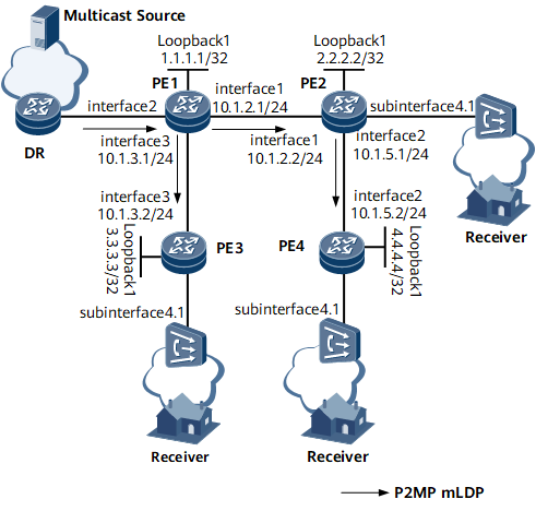
Networking Requirements
On the network shown in Figure 1, PE1, PE2, PE3, and PE4 use BGP AD to establish a full-mesh multicast VPLS network. PE1 functions as the root node, PE2 as a bud node, and PE3 and PE4 as leaf nodes. (The configurations on bud and leaf nodes are the same.) To carry multicast services, configure mLDP P2MP tunnels. The configuration simplifies network deployment.

Configuration Roadmap
The configuration roadmap is as follows:
Configure an IP address and a routing protocol for each interface to ensure IP connectivity at the network layer. This example uses OSPF as the routing protocol.
Configure an MPLS LSR ID and enable MPLS, MPLS LDP, and mLDP P2MP on each PE globally.
Configure a local LDP session on each PE.
Configure BGP AD VPLS on each PE.
Configure PE1 as the root node.
Configure PE2, PE3, and PE4 as leaf nodes.
Data Preparation
To complete the configuration, you need the following data:
IP addresses of all interfaces
OSPF process ID (100) and area ID (0.0.0.0) for each PE
BGP AS number for each PE
VSI name, VPLS ID, and VPN targets for each PE
Number of the interface bound to each VSI
IP address of the mLDP P2MP tunnel's root node (1.1.1.1)
Procedure
- Configure an IP address and a routing protocol for each interface to ensure IP connectivity at the network layer.
For configuration details, see Configuration Files in this section.
- Configure an MPLS LSR ID and enable MPLS, MPLS LDP, and mLDP P2MP on each PE globally.
# Configure PE1.
<PE1> system-view
[~PE1] mpls lsr-id 1.1.1.1
[*PE1] mpls
[*PE1-mpls] mpls ldp
[*PE1-mpls-ldp] mldp p2mp
[*PE1-mpls-ldp] quit
[*PE1-mpls] quit
[*PE1] commit
Repeat this step for PE2, PE3, and PE4. For configuration details, see Configuration Files in this section.
- Configure a local LDP session on each PE.
# Configure PE1.
[~PE1] interface gigabitethernet0/1/0
[~PE1-GigabitEthernet0/1/0] mpls
[*PE1-GigabitEthernet0/1/0] mpls ldp
[*PE1-GigabitEthernet0/1/0] quit
[*PE1] interface gigabitethernet0/1/2
[*PE1-GigabitEthernet0/1/2] mpls
[*PE1-GigabitEthernet0/1/2] mpls ldp
[*PE1-GigabitEthernet0/1/2] commit
Repeat this step for PE2, PE3, and PE4. For configuration details, see Configuration Files in this section.
- Configure BGP AD VPLS on each PE.
# Configure PE1.
[~PE1] bgp 100
[*PE1-bgp] peer 2.2.2.2 as-number 100
[*PE1-bgp] peer 2.2.2.2 connect-interface loopback1
[*PE1-bgp] peer 3.3.3.3 as-number 100
[*PE1-bgp] peer 3.3.3.3 connect-interface loopback1
[*PE1-bgp] peer 4.4.4.4 as-number 100
[*PE1-bgp] peer 4.4.4.4 connect-interface loopback1
[*PE1-bgp] l2vpn-ad-family
[*PE1-bgp-af-l2vpn-ad] peer 2.2.2.2 enable
[*PE1-bgp-af-l2vpn-ad] peer 3.3.3.3 enable
[*PE1-bgp-af-l2vpn-ad] peer 4.4.4.4 enable
[*PE1-bgp-af-l2vpn-ad] quit
[*PE1-bgp] quit
[*PE1] mpls l2vpn
[*PE1-l2vpn] quit
[*PE1] vsi vsi1
[*PE1-vsi-vsi1] bgp-ad
[*PE1-vsi-vsi1-bgpad] vpls-id 2:2
[*PE1-vsi-vsi1-bgpad] vpn-target 2:2 import-extcommunity
[*PE1-vsi-vsi1-bgpad] vpn-target 2:2 export-extcommunity
[*PE1-vsi-vsi1-bgpad] quit
[*PE1-vsi-vsi1] quit
[*PE1] interface gigabitethernet0/1/1
[*PE1-GigabitEthernet0/1/1] l2 binding vsi vsi1
[*PE1-GigabitEthernet0/1/1] quit
[*PE1] commit
# Configure PE2.
[~PE2] bgp 100
[*PE2-bgp] peer 1.1.1.1 as-number 100
[*PE2-bgp] peer 1.1.1.1 connect-interface loopback1
[*PE2-bgp] l2vpn-ad-family
[*PE2-bgp-af-l2vpn-ad] peer 1.1.1.1 enable
[*PE2-bgp-af-l2vpn-ad] quit
[*PE2-bgp] quit
[*PE2] mpls l2vpn
[*PE2-l2vpn] quit
[*PE2] vsi vsi1
[*PE2-vsi-vsi1] bgp-ad
[*PE2-vsi-vsi1-bgpad] vpls-id 2:2
[*PE2-vsi-vsi1-bgpad] vpn-target 2:2 import-extcommunity
[*PE2-vsi-vsi1-bgpad] vpn-target 2:2 export-extcommunity
[*PE2-vsi-vsi1-bgpad] quit
[*PE2-vsi-vsi1] quit
[*PE2] interface gigabitethernet0/1/3.1
[*PE2-GigabitEthernet0/1/3.1] vlan-type dot1q 10
[*PE2-GigabitEthernet0/1/3.1] l2 binding vsi vsi1
[*PE2-GigabitEthernet0/1/3.1] quit
[*PE2] commit
# Configure PE3.
[~PE3] bgp 100
[*PE3-bgp] peer 1.1.1.1 as-number 100
[*PE3-bgp] peer 1.1.1.1 connect-interface loopback1
[*PE3-bgp] l2vpn-ad-family
[*PE3-bgp-af-l2vpn-ad] peer 1.1.1.1 enable
[*PE3-bgp-af-l2vpn-ad] quit
[*PE3-bgp] quit
[*PE3] mpls l2vpn
[*PE3] vsi vsi1
[*PE3-vsi-vsi1] bgp-ad
[*PE3-vsi-vsi1-bgpad] vpls-id 2:2
[*PE3-vsi-vsi1-bgpad] vpn-target 2:2 import-extcommunity
[*PE3-vsi-vsi1-bgpad] vpn-target 2:2 export-extcommunity
[*PE3-vsi-vsi1-bgpad] quit
[*PE3-vsi-vsi1] quit
[*PE3] interface gigabitethernet0/1/3.1
[*PE3-GigabitEthernet0/1/3.1] vlan-type dot1q 10
[*PE3-GigabitEthernet0/1/3.1] l2 binding vsi vsi1
[*PE3-GigabitEthernet0/1/3.1] quit
[*PE3] commit
# Configure PE4.
[~PE4] bgp 100
[*PE4-bgp] peer 1.1.1.1 as-number 100
[*PE4-bgp] peer 1.1.1.1 connect-interface loopback1
[*PE4-bgp] l2vpn-ad-family
[*PE4-bgp-af-l2vpn-ad] peer 1.1.1.1 enable
[*PE4-bgp-af-l2vpn-ad] quit
[*PE4-bgp] quit
[*PE4] mpls l2vpn
[*PE4] vsi vsi1
[*PE4-vsi-vsi1] bgp-ad
[*PE4-vsi-vsi1-bgpad] vpls-id 2:2
[*PE4-vsi-vsi1-bgpad] vpn-target 2:2 import-extcommunity
[*PE4-vsi-vsi1-bgpad] vpn-target 2:2 export-extcommunity
[*PE4-vsi-vsi1-bgpad] quit
[*PE4-vsi-vsi1] quit
[*PE4] interface gigabitethernet0/1/3.1
[*PE4-GigabitEthernet0/1/3.1] vlan-type dot1q 10
[*PE4-GigabitEthernet0/1/3.1] l2 binding vsi vsi1
[*PE4-GigabitEthernet0/1/3.1] quit
[*PE4] commit
- Configure PE1 as the root node.
# Configure PE1.
[~PE1] vsi vsi1
[*PE1-vsi-vsi1] inclusive-provider-tunnel
[*PE1-vsi-vsi1-inclusive] root
[*PE1-vsi-vsi1-inclusive-root] mldp p2mp
[*PE1-vsi-vsi1-inclusive-root-mldpp2mp] root-ip 1.1.1.1
[*PE1-vsi-vsi1-inclusive-root-mldpp2mp] quit
[*PE1-vsi-vsi1-inclusive-root] quit
[*PE1-vsi-vsi1-inclusive] quit
[*PE1-vsi-vsi1] quit
[*PE1] commit
- Configure PE2, PE3, and PE4 as leaf nodes.
# Configure PE2.
[~PE2] vsi vsi1
[*PE2-vsi-vsi1] inclusive-provider-tunnel
[*PE2-vsi-vsi1-inclusive] leaf
[*PE2-vsi-vsi1-inclusive-leaf] quit
[*PE2-vsi-vsi1-inclusive] quit
[*PE2-vsi-vsi1] quit
[*PE2] commit
Repeat this step for PE3 and PE4. For configuration details, see Configuration Files in this section.
- Verify the configuration.
After the configurations are complete, run the display vsi name inclusive-provider-tunnel command on PE1 to check mLDP P2MP tunnel information.
[~PE1] display vsi name vsi1 inclusive-provider-tunnel
VSI name: vsi1
 Ingress provider tunnel
    PMSI type      : P2MP mLDP
    Root ip        : 1.1.1.1
    Opaque value   : 01000400002001
    State         : up
    Leaf list count: 3
    Leaf list      : 2.2.2.2
                     3.3.3.3
                     4.4.4.4
  Egress provider tunnel
  Egress PMSI count: 0
Configuration Files
PE1 configuration file
#
sysname PE1
#
mpls lsr-id 1.1.1.1
mpls
#
mpls l2vpn
#
vsi vsi1
 bgp-ad
  vpls-id 2:2
  vpn-target 2:2 import-extcommunity
  vpn-target 2:2 export-extcommunity
 inclusive-provider-tunnel
  root
   mldp p2mp
    root-ip 1.1.1.1
#
mpls ldp
 mldp p2mp
#
interface GigabitEthernet0/1/0
 undo shutdown
 ip address 10.1.2.1 255.255.255.0
 mpls
 mpls ldp
#
interface GigabitEthernet0/1/1
 undo shutdown
 l2 binding vsi vsi1
#
interface GigabitEthernet0/1/2
 undo shutdown
 ip address 10.1.3.1 255.255.255.0
 mpls
 mpls ldp
#
interface LoopBack1
 ip address 1.1.1.1 255.255.255.255
#
bgp 100
 peer 2.2.2.2 as-number 100
 peer 2.2.2.2 connect-interface LoopBack1
 peer 3.3.3.3 as-number 100
 peer 3.3.3.3 connect-interface LoopBack1
 peer 4.4.4.4 as-number 100
 peer 4.4.4.4 connect-interface LoopBack1
 #
 l2vpn-ad-family
  peer 2.2.2.2 enable
  peer 3.3.3.3 enable
  peer 4.4.4.4 enable
 #
ospf 100
 area 0.0.0.0
  network 1.1.1.1 0.0.0.0
  network 10.1.2.0 0.0.0.255
  network 10.1.3.0 0.0.0.255
#
return
PE2 configuration file
#
sysname PE2
#
mpls lsr-id 2.2.2.2
mpls
#
mpls l2vpn
#
vsi vsi1
 bgp-ad
  vpls-id 2:2
  vpn-target 2:2 import-extcommunity
  vpn-target 2:2 export-extcommunity
 inclusive-provider-tunnel
  leaf
#
mpls ldp
 mldp p2mp
#
interface GigabitEthernet0/1/0
 undo shutdown
 ip address 10.1.2.2 255.255.255.0
 mpls
 mpls ldp
#
interface GigabitEthernet0/1/1
 undo shutdown
 ip address 10.1.5.1 255.255.255.0
 mpls
 mpls ldp
#
interface GigabitEthernet0/1/3.1
 vlan-type dot1q 10
 l2 binding vsi vsi1
#
interface LoopBack1
 ip address 2.2.2.2 255.255.255.255
#
bgp 100
 peer 1.1.1.1 as-number 100
 peer 1.1.1.1 connect-interface LoopBack1
 #
 l2vpn-ad-family
  peer 1.1.1.1 enable
 #
ospf 100
 area 0.0.0.0
  network 2.2.2.2 0.0.0.0
  network 10.1.2.0 0.0.0.255
  network 10.1.5.0 0.0.0.255
#
return
PE3 configuration file
#
sysname PE3
#
mpls lsr-id 3.3.3.3
mpls
#
mpls l2vpn
#
vsi vsi1
 bgp-ad
  vpls-id 2:2
  vpn-target 2:2 import-extcommunity
  vpn-target 2:2 export-extcommunity
 inclusive-provider-tunnel
  leaf
#
mpls ldp
 mldp p2mp
#
interface GigabitEthernet0/1/2
 undo shutdown
 ip address 10.1.3.2 255.255.255.0
 mpls
 mpls ldp
#
interface GigabitEthernet0/1/3.1
 vlan-type dot1q 10
 l2 binding vsi vsi1
#
interface LoopBack1
 ip address 3.3.3.3 255.255.255.255
#
bgp 100
 peer 1.1.1.1 as-number 100
 peer 1.1.1.1 connect-interface LoopBack1
 #
 l2vpn-ad-family
  peer 1.1.1.1 enable
#
ospf 100
 area 0.0.0.0
  network 3.3.3.3 0.0.0.0
  network 10.1.3.0 0.0.0.255
#
return
PE4 configuration file
#
sysname PE4
#
mpls lsr-id 4.4.4.4
mpls
#
mpls l2vpn
#
vsi vsi1
 bgp-ad
  vpls-id 2:2
  vpn-target 2:2 import-extcommunity
  vpn-target 2:2 export-extcommunity
 inclusive-provider-tunnel
  leaf
#
mpls ldp
 mldp p2mp
#
interface GigabitEthernet0/1/1
 undo shutdown
 ip address 10.1.5.2 255.255.255.0
 mpls
 mpls ldp
#
interface GigabitEthernet0/1/3.1
 vlan-type dot1q 10
 l2 binding vsi vsi1
#
interface LoopBack1
 ip address 4.4.4.4 255.255.255.255
#
bgp 100
 peer 1.1.1.1 as-number 100
 peer 1.1.1.1 connect-interface LoopBack1
 #
 l2vpn-ad-family
  peer 1.1.1.1 enable
#
ospf 100
 area 0.0.0.0
  network 4.4.4.4 0.0.0.0
  network 10.1.5.0 0.0.0.255
#
return