Example for Configuring Interworking Between LDP VPLS and BGP AD VPLS in PW Redundancy Mode
This section provides an example of configuring interworking between Label Distribution Protocol (LDP) virtual private LAN service (VPLS) and Border Gateway Protocol Auto-Discovery (BGP AD) VPLS in pseudo wire (PW) redundancy mode.
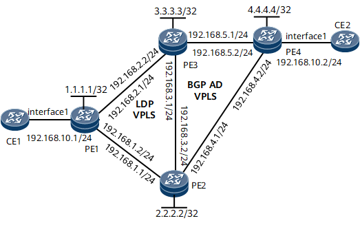
Networking Requirements
As shown in Figure 1, PE1 supports LDP VPLS, PE4 supports BGP AD VPLS, and PE2 and PE3 support both LDP VPLS and BGP AD VPLS. It is required that interworking between LDP VPLS and BGP AD VPLS be configured in PW redundancy mode for CE1 and CE2 to communicate.
- Establish a hub PW from PE1 to PE2 and from PE1 to PE3. The two PWs work in master/slave PW redundancy mode.
- Establish an LDP spoke PW from PE2 to PE1. Establish a BGP AD hub PW from PE2 to PE3 and from PE2 to PE4.
- Establish an LDP spoke PW from PE3 to PE1. Establish a BGP AD hub PW from PE3 to PE2 and from PE3 to PE4.
- Establish a BGP AD hub PW from PE4 to PE2 and from PE4 to PE3.

- Interface 1 in this example represents GE 0/1/2.
Device |
Interface |
IP Address |
|---|---|---|
PE1 |
GE 0/1/0 |
192.168.1.1/24 |
GE 0/1/1 |
192.168.2.1/24 |
|
GE 0/1/2 |
- |
|
Loopback 0 |
1.1.1.1/32 |
|
PE2 |
GE 0/1/0 |
192.168.1.2/24 |
GE 0/1/1 |
192.168.4.1/24 |
|
GE 0/1/2 |
192.168.3.2/24 |
|
Loopback 0 |
2.2.2.2/32 |
|
PE3 |
GE 0/1/0 |
192.168.5.1/24 |
GE 0/1/1 |
192.168.2.2/24 |
|
GE 0/1/2 |
192.168.3.1/24 |
|
Loopback 0 |
3.3.3.3/32 |
|
PE4 |
GE 0/1/0 |
192.168.5.2/24 |
GE 0/1/1 |
192.168.4.2/24 |
|
GE 0/1/2 |
- |
|
Loopback 0 |
4.4.4.4/32 |
|
CE1 |
GE 0/1/2 |
- |
GE 0/1/2.1 |
192.168.10.1/24 |
|
CE2 |
GE 0/1/2 |
- |
GE 0/1/2.1 |
192.168.10.2/24 |
Configuration Roadmap
The configuration roadmap is as follows:
- Configure an IP address and a routing protocol for each interface so that all PEs can communicate at the network layer.
Configure Multiprotocol Label Switching (MPLS) and public tunnels.
Configure PE1, PE2, and PE3 to form an LDP VPLS network.
Configure PE2, PE3, and PE4 to form a BGP AD VPLS network.
Configure PW redundancy (master/slave) on PE1.
Configure Media Access Control (MAC) Withdraw.
Data Preparation
To complete the configuration, you need the following data:
IP address, Open Shortest Path First (OSPF) process ID, and OSPF area ID of each interface, and label switching router (LSR) ID of each PE
Virtual switch instance (VSI) name, VSI ID, VPLS ID, virtual private network (VPN) targets, and BGP AS number
Number and virtual local area network (VLAN) ID of each interface bound to a VSI
PW redundancy protection group name, revertive switching mode, revertive switching delay, and PW priorities
Procedure
- Configure an IP address and a routing protocol for each interface on the backbone network so that PEs can communicate at the network layer.
This example uses OSPF as the routing protocol. For details about specific configurations, see the following configuration files.
After the configuration is complete, run the display ip routing-table command on PEs to verify that the PEs have learned each other's loopback interface IP address.
- Configure MPLS and public tunnels.
This example uses LDP LSPs as public tunnels. For details about specific configurations, see the following configuration files.
After the configuration is complete, run the display mpls ldp session command on PEs to verify that peer relationships have been established; run the display mpls lsp command to verify that LSPs have been established.
- Configure PE1, PE2, and PE3 to form an LDP VPLS network.
# Configure PE1.
<PE1> system-view
[~PE1] mpls l2vpn
[*PE1-l2vpn] quit
[*PE1] vsi vsi1 static
[*PE1-vsi-vsi1] pwsignal ldp
[*PE1-vsi-vsi1-ldp] vsi-id 1
[*PE1-vsi-vsi1-ldp] peer 2.2.2.2
[*PE1-vsi-vsi1-ldp] peer 3.3.3.3
[*PE1-vsi-vsi1-ldp] quit
[*PE1-vsi-vsi1] quit
[*PE1] commit
# Configure PE2.
<PE2> system-view
[~PE2] mpls l2vpn
[*PE2-l2vpn] quit
[*PE2] vsi vsi1
[*PE2-vsi-vsi1] pwsignal ldp
[*PE2-vsi-vsi1-ldp] vsi-id 1
[*PE2-vsi-vsi1-ldp] peer 1.1.1.1 upe
[*PE2-vsi-vsi1-ldp] quit
[*PE2-vsi-vsi1] quit
[*PE2] commit
# Configure PE3.
<PE3> system-view
[~PE3] mpls l2vpn
[*PE3-l2vpn] quit
[*PE3] vsi vsi1
[*PE3-vsi-vsi1] pwsignal ldp
[*PE3-vsi-vsi1-ldp] vsi-id 1
[*PE3-vsi-vsi1-ldp] peer 1.1.1.1 upe
[*PE3-vsi-vsi1-ldp] quit
[*PE3-vsi-vsi1] quit
[*PE3] commit
# On PE1, bind the attachment circuit (AC) interface to the VSI.
[~PE1] interface gigabitethernet0/1/2.1
[*PE1-GigabitEthernet0/1/2.1] vlan-type dot1q 10
[*PE1-GigabitEthernet0/1/2.1] l2 binding vsi vsi1
[*PE1-GigabitEthernet0/1/2.1] quit
[*PE1] commit
- Configure PE2, PE3, and PE4 to form a BGP AD VPLS network.
Enable BGP peers to exchange VPLS information.
# Configure PE2.
<PE2> system-view
[~PE2] bgp 100
[*PE2-bgp] peer 3.3.3.3 as-number 100
[*PE2-bgp] peer 3.3.3.3 connect-interface loopback0
[*PE2-bgp] peer 4.4.4.4 as-number 100
[*PE2-bgp] peer 4.4.4.4 connect-interface loopback0
[*PE2-bgp] l2vpn-ad-family
[*PE2-bgp-af-l2vpn-ad] peer 3.3.3.3 enable
[*PE2-bgp-af-l2vpn-ad] peer 4.4.4.4 enable
[*PE2-bgp-af-l2vpn-ad] quit
[*PE2-bgp] quit
[*PE2] commit
# Configure PE3.
[~PE3] bgp 100
[*PE3-bgp] peer 2.2.2.2 as-number 100
[*PE3-bgp] peer 2.2.2.2 connect-interface loopback0
[*PE3-bgp] peer 4.4.4.4 as-number 100
[*PE3-bgp] peer 4.4.4.4 connect-interface loopback0
[*PE3-bgp] l2vpn-ad-family
[*PE3-bgp-af-l2vpn-ad] peer 2.2.2.2 enable
[*PE3-bgp-af-l2vpn-ad] peer 4.4.4.4 enable
[*PE3-bgp-af-l2vpn-ad] quit
[*PE3-bgp] quit
[*PE3] commit
# Configure PE4.
<PE4> system-view
[~PE4] bgp 100
[*PE4-bgp] peer 2.2.2.2 as-number 100
[*PE4-bgp] peer 2.2.2.2 connect-interface loopback0
[*PE4-bgp] peer 3.3.3.3 as-number 100
[*PE4-bgp] peer 3.3.3.3 connect-interface loopback0
[*PE4-bgp] l2vpn-ad-family
[*PE4-bgp-af-l2vpn-ad] peer 2.2.2.2 enable
[*PE4-bgp-af-l2vpn-ad] peer 3.3.3.3 enable
[*PE4-bgp-af-l2vpn-ad] quit
[*PE4-bgp] quit
[*PE4] commit
Create VSIs and configure the BGP AD signaling.
# Configure PE2.
[~PE2] vsi vsi1
[*PE2-vsi-vsi1] bgp-ad
[*PE2-vsi-vsi1--bgpad] vpls-id 192.168.0.0:1
[*PE2-vsi-vsi1--bgpad] vpn-target 100:1 import-extcommunity
[*PE2-vsi-vsi1--bgpad] vpn-target 100:1 export-extcommunity
[*PE2-vsi-vsi1--bgpad] quit
[*PE2-vsi-vsi1] quit
[*PE2] commit
On PE2, the LDP and BGP AD PWs must be configured in the same VSI.
# Configure PE3.
[~PE3] vsi vsi1
[*PE3-vsi-vsi1] bgp-ad
[*PE3-vsi-vsi1--bgpad] vpls-id 192.168.0.0:1
[*PE3-vsi-vsi1--bgpad] vpn-target 100:1 import-extcommunity
[*PE3-vsi-vsi1--bgpad] vpn-target 100:1 export-extcommunity
[*PE3-vsi-vsi1--bgpad] quit
[*PE3-vsi-vsi1] quit
[*PE3] commit
On PE3, the LDP and BGP AD PWs must be configured in the same VSI.
# Configure PE4.
[~PE4] mpls l2vpn
[*PE4-l2vpn] quit
[*PE4] vsi vsi1
[*PE4-vsi-vsi1] bgp-ad
[*PE4-vsi-vsi1-bgpad] vpls-id 192.168.0.0:1
[*PE4-vsi-vsi1-bgpad] vpn-target 100:1 import-extcommunity
[*PE4-vsi-vsi1-bgpad] vpn-target 100:1 export-extcommunity
[*PE4-vsi-vsi1-bgpad] quit
[*PE4-vsi-vsi1] quit
[*PE4] commit
# On PE4, bind the AC interface to the VSI.
[~PE4] interface gigabitethernet0/1/2.1
[*PE4-GigabitEthernet0/1/2.1] vlan-type dot1q 10
[*PE4-GigabitEthernet0/1/2.1] l2 binding vsi vsi1
[*PE4-GigabitEthernet0/1/2.1] quit
[*PE4] commit
- Configure PW redundancy (master/slave) on PE1.
Configure a PW protection group on PE1 and specify the PW redundancy mode as master/slave. Add the hub PWs from PE1 to PE2 and PE3 to the PW protection group, specify the priorities of the PWs, and set the revertive switching delay to 60s.
[~PE1] vsi vsi1
[*PE1-vsi-vsi1] pwsignal ldp
[*PE1-vsi-vsi1-ldp] protect-group vsi1
[*PE1-vsi-vsi1-ldp-protect-group-vsi1] protect-mode pw-redundancy master
[*PE1-vsi-vsi1-ldp-protect-group-vsi1] peer 2.2.2.2 preference 1
[*PE1-vsi-vsi1-ldp-protect-group-vsi1] peer 3.3.3.3 preference 2
[*PE1-vsi-vsi1-ldp-protect-group-vsi1] reroute delay 60
[*PE1-vsi-vsi1-ldp-protect-group-vsi1] quit
[*PE1-vsi-vsi1-ldp] quit
[*PE1-vsi-vsi1] quit
[*PE1] commit
Configure Bidirectional Forwarding Detection (BFD) for PW to monitor the primary PW.
# Configure PE1.
[~PE1] bfd
[*PE1-bfd] quit
[*PE1] bfd p1 bind pw vsi vsi1 peer 2.2.2.2 remote-peer 2.2.2.2 pw-ttl auto-calculate
[*PE1-bfd-lsp-session-p1] discriminator local 104
[*PE1-bfd-lsp-session-p1] discriminator remote 401
[*PE1-bfd-lsp-session-p1] commit
[~PE1-bfd-lsp-session-p1] quit
# Configure PE2.
[~PE2] bfd
[*PE2-bfd] quit
[*PE2] bfd p1 bind pw vsi vsi1 peer 1.1.1.1 remote-peer 1.1.1.1 pw-ttl auto-calculate
[*PE2-bfd-lsp-session-p1] discriminator local 401
[*PE2-bfd-lsp-session-p1] discriminator remote 104
[*PE2-bfd-lsp-session-p1] commit
[~PE2-bfd-lsp-session-p1] quit
Check the primary/secondary status of PWs.
# On PE1, check the PW status.
[~PE1] display vsi verbose
 ***VSI Name               : vsi1
    Administrator VSI      : no
    Isolate Spoken         : disable
    VSI Index              : 0
    PW Signaling           : ldp
    Member Discovery Style : static
    Bridge-domain Mode     : disable
    PW MAC Learn Style     : unqualify
    Encapsulation Type     : vlan
    MTU                    : 1500
    Diffserv Mode          : uniform
    Service Class          : --
    Color                  : --
    DomainId               : 255
    Domain Name            :
    Ignore AcState         : disable
    P2P VSI                : disable
    Create Time            : 0 days, 1 hours, 12 minutes, 47 seconds
    VSI State              : up

    VSI ID                 : 1
   *Peer Router ID         : 2.2.2.2
    primary or secondary   : primary
    ignore-standby-state   : no
    VC Label               : 1028
    Peer Type              : dynamic
    Session                : up
    Tunnel ID              : 0x800808
    Broadcast Tunnel ID    : 0x800808
    Broad BackupTunnel ID  : 0x0
    CKey                   : 2
    NKey                   : 1
    Stp Enable             : 0
    PwIndex                : 0
    Control Word           : disable
   *Peer Router ID         : 3.3.3.3
    primary or secondary   : primary
    ignore-standby-state   : no
    VC Label               : 1029
    Peer Type              : dynamic
    Session                : up
    Tunnel ID              : 0x800809
    Broadcast Tunnel ID    : 0x800809
    Broad BackupTunnel ID  : 0x0
    CKey                   : 4
    NKey                   : 3
    Stp Enable             : 0
    PwIndex                : 0
    Control Word           : disable

    Interface Name         : GigabitEthernet0/1/2.1
    State                  : up
    Access Port            : false
    Last Up Time           : 2012/12/24 19:06:41
    Total Up Time          : 0 days, 1 hours, 3 minutes, 5 seconds

  **PW Information:

   *Peer Ip Address        : 3.3.3.3
    PW State               : backup
    Local VC Label         : 1029
    Remote VC Label        : 1028
    Remote Control Word    : disable
   PW Type                : label
    Tunnel ID              : 0x800809
    Broadcast Tunnel ID    : 0x800809
    Broad BackupTunnel ID  : 0x0
    Ckey                   : 0x4
    Nkey                   : 0x3
    Main PW Token          : 0x800809
    Slave PW Token         : 0x0
    Tnl Type               : LSP
    OutInterface           : GigabitEthernet0/1/1
    Backup OutInterface    :
    Stp Enable             : 0
    PW Last Up Time        : 2012/12/24 19:06:41
    PW Total Up Time       : 0 days, 1 hours, 3 minutes, 5 seconds
   *Peer Ip Address        : 2.2.2.2
    PW State               : up
    Local VC Label         : 1028
    Remote VC Label        : 1032
    Remote Control Word    : disable
    PW Type                : label
    Tunnel ID              : 0x800808
    Broadcast Tunnel ID    : 0x800808
    Broad BackupTunnel ID  : 0x0
    Ckey                   : 0x2
    Nkey                   : 0x1
    Main PW Token          : 0x800808
    Slave PW Token         : 0x0
    Tnl Type               : LSP
    OutInterface           : GigabitEthernet0/1/0
    Backup OutInterface    :
    Stp Enable             : 0
    PW Last Up Time        : 2012/12/24 19:52:15
    PW Total Up Time       : 0 days, 0 hours, 17 minutes, 33 seconds
# On PE2, check the PW status.
[~PE2] display vsi verbose
 ***VSI Name               : vsi1
    Administrator VSI      : no
    Isolate Spoken         : disable
    VSI Index              : 0
    PW Signaling           : ldp bgpad
    Member Discovery Style : --
    Bridge-domain Mode     : disable
    PW MAC Learn Style     : unqualify
    Encapsulation Type     : vlan
    MTU                    : 1500
    Diffserv Mode          : uniform
    Service Class          : --
    Color                  : --
    DomainId               : 255
    Domain Name            :
    Ignore AcState         : disable
    P2P VSI                : disable
    Create Time            : 0 days, 1 hours, 15 minutes, 29 seconds
    VSI State              : up

    VPLS ID                : 192.168.0.0:1
    RD                     : 192.168.0.0:1
    Import vpn target      : 100:1
    Export vpn target      : 100:1
    BGPAD VSI ID           : 2.2.2.2

   *Peer Router ID         : 4.4.4.4
    VPLS ID                : 192.168.0.0:1
    SAII                   : 2.2.2.2
    TAII                   : 4.4.4.4
    VC Label               : 1034
    Peer Type              : dynamic
    Session                : up
    Tunnel ID              : 0x80081a
    Broadcast Tunnel ID    : 0x80081a
    CKey                   : 10
    NKey                   : 9

   *Peer Router ID         : 3.3.3.3
    VPLS ID                : 192.168.0.0:1
    SAII                   : 2.2.2.2
    TAII                   : 3.3.3.3
    VC Label               : 1035
    Peer Type              : dynamic
    Session                : up
    Tunnel ID              : 0x80081b
    Broadcast Tunnel ID    : 0x80081b
    CKey                   : 11
    NKey                   : 7

    VSI ID                 : 1
   *Peer Router ID         : 1.1.1.1
    primary or secondary   : primary
    ignore-standby-state   : no
    VC Label               : 1032
    Peer Type              : dynamic
    Session                : up
    Tunnel ID              : 0x800818
    Broadcast Tunnel ID    : 0x800818
    Broad BackupTunnel ID  : 0x0
    CKey                   : 6
    NKey                   : 5
    Stp Enable             : 0
    PwIndex                : 0
    Control Word           : disable
   *Peer Router ID         : 3.3.3.3
    primary or secondary   : primary
    ignore-standby-state   : no
    VC Label               : 1033
    Peer Type              : dynamic
    Session                : up
    Tunnel ID              : 0x800819
    Broadcast Tunnel ID    : 0x800819
    Broad BackupTunnel ID  : 0x0
    CKey                   : 8
    NKey                   : 7
    Stp Enable             : 0
    PwIndex                : 0
    Control Word           : disable

  **PW Information:

   *Peer Ip Address        : 1.1.1.1
    PW State               : up
    Local VC Label         : 1032
    Remote VC Label        : 1028
    Remote Control Word    : disable
    PW Type                : MEHVPLS
    Tunnel ID              : 0x800818
    Broadcast Tunnel ID    : 0x800818
    Broad BackupTunnel ID  : 0x0
    Ckey                   : 0x6
    Nkey                   : 0x5
    Main PW Token          : 0x800818
    Slave PW Token         : 0x0
    Tnl Type               : LSP
    OutInterface           : GigabitEthernet0/1/0
    Backup OutInterface    :
    Stp Enable             : 0
    PW Last Up Time        : 2012/12/24 19:52:15
    PW Total Up Time       : 0 days, 0 hours, 20 minutes, 34 seconds
   *Peer Ip Address        : 3.3.3.3
    PW State               : up
    Local VC Label         : 1033
    Remote VC Label        : 1037
    Remote Control Word    : disable
    PW Type                : label
    Tunnel ID              : 0x800819
    Broadcast Tunnel ID    : 0x800819
    Broad BackupTunnel ID  : 0x0
    Ckey                   : 0x8
    Nkey                   : 0x7
    Main PW Token          : 0x800819
    Slave PW Token         : 0x0
    Tnl Type               : LSP
    OutInterface           : GigabitEthernet0/1/2
    Backup OutInterface    :
    Stp Enable             : 0
    PW Last Up Time        : 2012/12/24 19:52:59
    PW Total Up Time       : 0 days, 0 hours, 20 minutes, 18 seconds
   *Peer Ip Address        : 3.3.3.3
    PW State               : up
    Local VC Label         : 1035
    Remote VC Label        : 1038
    Remote Control Word    : disable
    PW Type                : label
    Tunnel ID              : 0x80081b
    Broadcast Tunnel ID    : 0x80081b
    Broad BackupTunnel ID  : 0x0
    Ckey                   : 0xb
    Nkey                   : 0x7
    Main PW Token          : 0x80081b
    Slave PW Token         : 0x0
    Tnl Type               : LSP
    OutInterface           : GigabitEthernet0/1/2
    Backup OutInterface    :
    Stp Enable             : 0
    PW Last Up Time        : 2012/12/24 19:59:01
    PW Total Up Time       : 0 days, 0 hours, 13 minutes, 50 seconds
   *Peer Ip Address        : 4.4.4.4
    PW State               : up
    Local VC Label         : 1034
    Remote VC Label        : 1037
    Remote Control Word    : disable
    PW Type                : label
    Tunnel ID              : 0x80081a
    Broadcast Tunnel ID    : 0x80081a
    Broad BackupTunnel ID  : 0x0
    Ckey                   : 0xa
    Nkey                   : 0x9
    Main PW Token          : 0x80081a
    Slave PW Token         : 0x0
    Tnl Type               : LSP
    OutInterface           : GigabitEthernet0/1/1
    Backup OutInterface    :
    Stp Enable             : 0
    PW Last Up Time        : 2012/12/24 20:00:19
    PW Total Up Time       : 0 days, 0 hours, 12 minutes, 33 seconds
- Configure MAC Withdraw.
# Configure PE1.
[~PE1] vsi vsi1
[*PE1-vsi-vsi1] mac-withdraw enable
[*PE1-vsi-vsi1] quit
[*PE1] commit
# Configure PE2.
[~PE2] vsi vsi1
[*PE2-vsi-vsi1] mac-withdraw enable
[*PE2-vsi-vsi1] mac-withdraw propagate enable
[*PE2-vsi-vsi1] quit
[*PE2] commit
# Configure PE3.
[~PE3] vsi vsi1
[*PE3-vsi-vsi1] mac-withdraw enable
[*PE3-vsi-vsi1] mac-withdraw propagate enable
[*PE3-vsi-vsi1] quit
[*PE3] commit
- Configure CEs.
# Configure CE1.
<CE1> system-view
[~CE1] interface gigabitethernet0/1/2
[*CE1-GigabitEthernet0/1/2] undo shutdown
[*CE1-GigabitEthernet0/1/2] quit
[*CE1] interface gigabitethernet0/1/2.1
[*CE1-GigabitEthernet0/1/2.1] vlan-type dot1q 10
[*CE1-GigabitEthernet0/1/2.1] ip address 192.168.10.1 255.255.255.0
[*CE1-GigabitEthernet0/1/2.1] quit
[*CE1] commit
# Configure CE2.
<CE2> system-view
[~CE2] interface gigabitethernet0/1/2
[*CE2-GigabitEthernet0/1/2] undo shutdown
[*CE2-GigabitEthernet0/1/2] quit
[*CE2] interface gigabitethernet0/1/2.1
[*CE2-GigabitEthernet0/1/2.1] vlan-type dot1q 10
[*CE2-GigabitEthernet0/1/2.1] ip address 192.168.10.2 255.255.255.0
[*CE2-GigabitEthernet0/1/2.1] quit
[*CE2] commit
- Verify the configuration.
Ping CE2 from CE1. The command output shows that the ping is successful.
[~CE1] ping 192.168.10.2
  PING 192.168.10.2: 56  data bytes, press CTRL_C to break
    Reply from 192.168.10.2: bytes=56 Sequence=1 ttl=255 time=140 ms
    Reply from 192.168.10.2: bytes=56 Sequence=2 ttl=255 time=140 ms
    Reply from 192.168.10.2: bytes=56 Sequence=3 ttl=255 time=140 ms
    Reply from 192.168.10.2: bytes=56 Sequence=4 ttl=255 time=110 ms
    Reply from 192.168.10.2: bytes=56 Sequence=5 ttl=255 time=180 ms

  --- 192.168.10.2 ping statistics ---
    5 packet(s) transmitted
    5 packet(s) received
    0.00% packet loss
    round-trip min/avg/max = 110/142/180 ms
Configuration Files
PE1 configuration file
#
sysname PE1
#
bfd
#
mpls lsr-id 1.1.1.1
mpls
#
mpls l2vpn
#
vsi vsi1 static
 pwsignal ldp
  vsi-id 1
  peer 2.2.2.2
  peer 3.3.3.3
  protect-group vsi1
   protect-mode pw-redundancy master
   reroute delay 60
   peer 2.2.2.2 preference 1
   peer 3.3.3.3 preference 2
 mac-withdraw enable
#
mpls ldp
#
interface GigabitEthernet0/1/0
 undo shutdown
 ip address 192.168.1.1 255.255.255.0
 mpls
 mpls ldp
#
interface GigabitEthernet0/1/1
 undo shutdown
 ip address 192.168.2.1 255.255.255.0
 mpls
 mpls ldp
#
interface GigabitEthernet0/1/2
 undo shutdown
#
interface GigabitEthernet0/1/2.1
 vlan-type dot1q 10
 l2 binding vsi vsi1
#
interface LoopBack0
 ip address 1.1.1.1 255.255.255.255
#
ospf 1
 area 0.0.0.0
  network 1.1.1.1 0.0.0.0
  network 192.168.1.0 0.0.0.255
  network 192.168.2.0 0.0.0.255
#
bfd p1 bind pw vsi vsi1 peer 2.2.2.2 remote-peer 2.2.2.2 pw-ttl auto-calculate
 discriminator local 104
 discriminator remote 401
 commit
#
return
PE2 configuration file
#
sysname PE2
#
bfd
#
mpls lsr-id 2.2.2.2
mpls
#
mpls l2vpn
#
vsi vsi1
 pwsignal ldp
  vsi-id 1
  peer 1.1.1.1 upe
 bgp-ad
  vpls-id 192.168.0.0:1
  vpn-target 100:1 import-extcommunity
  vpn-target 100:1 export-extcommunity
 mac-withdraw enable
 mac-withdraw propagate enable
#
mpls ldp
#
interface GigabitEthernet0/1/0
 undo shutdown
 ip address 192.168.1.2 255.255.255.0
 mpls
 mpls ldp
#
interface GigabitEthernet0/1/1
 undo shutdown
 ip address 192.168.4.1 255.255.255.0
 mpls
 mpls ldp
#
interface GigabitEthernet0/1/2
 undo shutdown
 ip address 192.168.3.2 255.255.255.0
 mpls
 mpls ldp
#
interface LoopBack0
 ip address 2.2.2.2 255.255.255.255
#
bgp 100
 peer 3.3.3.3 as-number 100
 peer 3.3.3.3 connect-interface LoopBack0
 peer 4.4.4.4 as-number 100
 peer 4.4.4.4 connect-interface LoopBack0
 #
 ipv4-family unicast
  peer 3.3.3.3 enable
  peer 4.4.4.4 enable
 #
 l2vpn-ad-family
  policy vpn-target
  peer 3.3.3.3 enable
  peer 4.4.4.4 enable
#
ospf 1
 area 0.0.0.0
  network 2.2.2.2 0.0.0.0
  network 192.168.1.0 0.0.0.255
  network 192.168.3.0 0.0.0.255
  network 192.168.4.0 0.0.0.255
#
bfd p1 bind pw vsi vsi1 peer 1.1.1.1 remote-peer 1.1.1.1 pw-ttl auto-calculate
 discriminator local 401
 discriminator remote 104
 commit
#
return
PE3 configuration file
#
sysname PE3
#
mpls lsr-id 3.3.3.3
mpls
#
mpls l2vpn
#
vsi vsi1
 pwsignal ldp
  vsi-id 1
  peer 1.1.1.1 upe
 bgp-ad
  vpls-id 192.168.0.0:1
  vpn-target 100:1 import-extcommunity
  vpn-target 100:1 export-extcommunity
 mac-withdraw enable
 mac-withdraw propagate enable
#
mpls ldp
#
interface GigabitEthernet0/1/0
 undo shutdown
 ip address 192.168.5.1 255.255.255.0
 mpls
 mpls ldp
#
interface GigabitEthernet0/1/1
 undo shutdown
 ip address 192.168.2.2 255.255.255.0
 mpls
 mpls ldp
#
interface GigabitEthernet0/1/2
 undo shutdown
 ip address 192.168.3.1 255.255.255.0
 mpls
 mpls ldp
#
interface LoopBack0
 ip address 3.3.3.3 255.255.255.255
#
bgp 100
 peer 2.2.2.2 as-number 100
 peer 2.2.2.2 connect-interface LoopBack0
 peer 4.4.4.4 as-number 100
 peer 4.4.4.4 connect-interface LoopBack0
 #
 ipv4-family unicast
  peer 2.2.2.2 enable
  peer 4.4.4.4 enable
 #
 l2vpn-ad-family
  policy vpn-target
  peer 2.2.2.2 enable
  peer 4.4.4.4 enable
#
ospf 1
 area 0.0.0.0
  network 3.3.3.3 0.0.0.0
  network 192.168.2.0 0.0.0.255
  network 192.168.3.0 0.0.0.255
  network 192.168.4.0 0.0.0.255
  network 192.168.5.0 0.0.0.255
#
return
PE4 configuration file
#
sysname PE4
#
mpls lsr-id 4.4.4.4
mpls
#
mpls l2vpn
#
vsi vsi1
 bgp-ad
  vpls-id 192.168.0.0:1
  vpn-target 100:1 import-extcommunity
  vpn-target 100:1 export-extcommunity
#
mpls ldp
#
interface GigabitEthernet0/1/0
 undo shutdown
 ip address 192.168.5.2 255.255.255.0
 mpls
 mpls ldp
#
interface GigabitEthernet0/1/1
 undo shutdown
 ip address 192.168.4.2 255.255.255.0
 mpls
 mpls ldp
#
interface GigabitEthernet0/1/2
 undo shutdown
#
interface GigabitEthernet0/1/2.1
 vlan-type dot1q 10
 l2 binding vsi vsi1
#
interface LoopBack0
 ip address 4.4.4.4 255.255.255.255
#
bgp 100
 peer 2.2.2.2 as-number 100
 peer 2.2.2.2 connect-interface LoopBack0
 peer 3.3.3.3 as-number 100
 peer 3.3.3.3 connect-interface LoopBack0
 #
 ipv4-family unicast
  peer 2.2.2.2 enable
  peer 3.3.3.3 enable
 #
 l2vpn-ad-family
  policy vpn-target
  peer 2.2.2.2 enable
  peer 3.3.3.3 enable
#
ospf 1
 area 0.0.0.0
  network 4.4.4.4 0.0.0.0
  network 192.168.4.0 0.0.0.255
  network 192.168.5.0 0.0.0.255
  network 192.168.6.0 0.0.0.255
#
return
CE1 configuration file
#
sysname CE1
#
interface GigabitEthernet0/1/2
 undo shutdown
#
interface GigabitEthernet0/1/2.1
 vlan-type dot1q 10
 ip address 192.168.10.1 255.255.255.0
#
return
CE2 configuration file
#
sysname CE2
#
interface GigabitEthernet0/1/2
 undo shutdown
#
interface GigabitEthernet0/1/2.1
 vlan-type dot1q 10
 ip address 192.168.10.2 255.255.255.0
#
return