Example for Configuring Interworking Between LDP VPLS and BGP VPLS
To enable an LDP VPLS network to communicate with a BGP VPLS network, configure interworking between LDP VPLS and BGP VPLS.
Networking Requirements
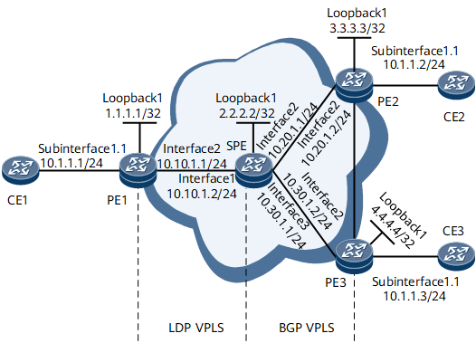
As shown in Figure 1, an LDP VPLS network is deployed between PE1 and the SPE, a BGP VPLS network is deployed among PE2, PE3, and the SPE. Interworking between LDP VPLS and BGP VPLS needs to be configured for CE1, CE2, and CE3 to communicate.

Configuration Roadmap
The configuration roadmap is as follows:
Configure an IGP and basic MPLS functions on the backbone network.
Establish an LSP between each PE and the SPE.
Enable MPLS L2VPN on the PEs and SPE.
Configure the PEs and SPE to exchange VPLS information as BGP peers.
Configure a hybrid VSI on the SPE.
Bind AC interfaces to VSIs.
Data Preparation
To complete the configuration, you need the following data:
Peer IP addresses
VSI names
Names and VLAN IDs of the AC interfaces to be bound to VSIs
Procedure
- Assign an IP address to each device interface.
# Configure CE1.
<HUAWEI> system-view
[~HUAWEI] sysname CE1
[*HUAWEI] commit
[~CE1] interface gigabitethernet 0/1/0.1
[*CE1-GigabitEthernet0/1/0.1] ip address 10.1.1.1 24
[*CE1-GigabitEthernet0/1/0.1] quit
[*CE1] commit
# Configure CE2.
<HUAWEI> system-view
[~HUAWEI] sysname CE2
[*HUAWEI] commit
[~CE2] interface gigabitethernet 0/1/0.1
[*CE2-GigabitEthernet0/1/0.1] ip address 10.1.1.2 24
[*CE2-GigabitEthernet0/1/0.1] quit
[*CE2] commit
# Configure CE3.
<HUAWEI> system-view
[~HUAWEI] sysname CE3
[*HUAWEI] commit
[~CE3] interface gigabitethernet 0/1/0.1
[*CE3-GigabitEthernet0/1/0.1] ip address 10.1.1.3 24
[*CE3-GigabitEthernet0/1/0.1] quit
[*CE3] commit
# Configure PE1.
<HUAWEI> system-view
[~HUAWEI] sysname PE1
[*HUAWEI] commit
[~PE1] interface loopback1
[*PE1-Loopback1] ip address 1.1.1.1 32
[*PE1-Loopback1] quit
[*PE1] interface gigabitethernet 0/1/8
[*PE1-GigabitEthernet0/1/8] ip address 10.10.1.1 24
[*PE1-GigabitEthernet0/1/8] quit
[*PE1] commit
# Configure the SPE.
<HUAWEI> system-view
[~HUAWEI] sysname SPE
[*HUAWEI] commit
[~SPE] interface loopback1
[*SPE-Loopback1] ip address 2.2.2.2 32
[*SPE-Loopback1] quit
[*SPE] interface gigabitethernet 0/1/0
[*SPE-GigabitEthernet0/1/0] ip address 10.10.1.2 24
[*SPE-GigabitEthernet0/1/0] quit
[*SPE] interface gigabitethernet 0/1/8
[*SPE-GigabitEthernet0/1/8] ip address 10.20.1.1 24
[*SPE-GigabitEthernet0/1/8] quit
[*SPE] interface gigabitethernet 0/1/16
[*SPE-GigabitEthernet0/1/16] ip address 10.30.1.1 24
[*SPE-GigabitEthernet0/1/16] quit
[*SPE] commit
# Configure PE2.
<HUAWEI> system-view
[~HUAWEI] sysname PE2
[*HUAWEI] commit
[~PE2] interface loopback1
[*PE2-Loopback1] ip address 3.3.3.3 32
[*PE2-Loopback1] quit
[*PE2] interface gigabitethernet 0/1/8
[*PE2-GigabitEthernet0/1/8] ip address 10.20.1.2 24
[*PE2-GigabitEthernet0/1/8] quit
[*PE2] commit
# Configure PE3.
<HUAWEI> system-view
[~HUAWEI] sysname PE3
[*HUAWEI] commit
[~PE3] interface loopback1
[*PE3-Loopback1] ip address 4.4.4.4 32
[*PE3-Loopback1] quit
[*PE3] interface gigabitethernet 0/1/8
[*PE2-GigabitEthernet0/1/8] ip address 10.30.1.2 24
[*PE2-GigabitEthernet0/1/8] quit
[*PE2] commit
- Configure an IGP. In this example, OSPF is used.
# Configure PE1.
[~PE1] ospf 1
[*PE1-ospf-1] area 0.0.0.0
[*PE1-ospf-1-area-0.0.0.0] network 1.1.1.1 0.0.0.0
[*PE1-ospf-1-area-0.0.0.0] network 10.10.1.0 0.0.0.255
[*PE1-ospf-1-area-0.0.0.0] quit
[*PE1-ospf-1] quit
[*PE1] commit
# Configure the SPE.
[~SPE] ospf 1
[*SPE-ospf-1] area 0.0.0.0
[*SPE-ospf-1-area-0.0.0.0] network 2.2.2.2 0.0.0.0
[*SPE-ospf-1-area-0.0.0.0] network 10.10.1.0 0.0.0.255
[*SPE-ospf-1-area-0.0.0.0] network 10.20.1.0 0.0.0.255
[*SPE-ospf-1-area-0.0.0.0] network 10.30.1.0 0.0.0.255
[*SPE-ospf-1-area-0.0.0.0] quit
[*SPE-ospf-1] quit
[*SPE] commit
# Configure PE2.
[~PE2] ospf 1
[*PE2-ospf-1] area 0.0.0.0
[*PE2-ospf-1-area-0.0.0.0] network 3.3.3.3 0.0.0.0
[*PE2-ospf-1-area-0.0.0.0] network 10.20.1.0 0.0.0.255
[*PE2-ospf-1-area-0.0.0.0] quit
[*PE2-ospf-1] quit
[*PE2] commit
# Configure PE3.
[~PE3] ospf 1
[*PE3-ospf-1] area 0.0.0.0
[*PE3-ospf-1-area-0.0.0.0] network 4.4.4.4 0.0.0.0
[*PE3-ospf-1-area-0.0.0.0] network 10.30.1.0 0.0.0.255
[*PE3-ospf-1-area-0.0.0.0] quit
[*PE3-ospf-1] quit
[*PE3] commit
- Configure basic MPLS functions and establish LSPs.
# Configure PE1.
[~PE1] mpls lsr-id 1.1.1.1
[*PE1] mpls
[*PE1-mpls] quit
[*PE1] mpls ldp
[*PE1-mpls-ldp] quit
[*PE1] interface gigabitethernet 0/1/8
[*PE1-GigabitEthernet0/1/8] mpls
[*PE1-GigabitEthernet0/1/8] mpls ldp
[*PE1-GigabitEthernet0/1/8] quit
[*PE1] commit
# Configure the SPE.
[~SPE] mpls lsr-id 2.2.2.2
[*SPE] mpls
[*SPE-mpls] quit
[*SPE] mpls ldp
[*SPE-mpls-ldp] quit
[*SPE] interface gigabitethernet 0/1/0
[*SPE-GigabitEthernet0/1/0] mpls
[*SPE-GigabitEthernet0/1/0] mpls ldp
[*SPE-GigabitEthernet0/1/0] quit
[*SPE] interface gigabitethernet 0/1/8
[*SPE-GigabitEthernet0/1/8] mpls
[*SPE-GigabitEthernet0/1/8] mpls ldp
[*SPE-GigabitEthernet0/1/8] quit
[*SPE] interface gigabitethernet 0/1/16
[*SPE-GigabitEthernet0/1/16] mpls
[*SPE-GigabitEthernet0/1/16] mpls ldp
[*SPE-GigabitEthernet0/1/16] quit
[*SPE] commit
# Configure PE2.
[~PE2] mpls lsr-id 3.3.3.3
[*PE2] mpls
[*PE2-mpls] quit
[*PE2] mpls ldp
[*PE2-mpls-ldp] quit
[*PE2] interface gigabitethernet 0/1/8
[*PE2-GigabitEthernet0/1/8] mpls
[*PE2-GigabitEthernet0/1/8] mpls ldp
[*PE2-GigabitEthernet0/1/8] quit
[*PE2] commit
# Configure PE3.
[~PE3] mpls lsr-id 4.4.4.4
[*PE3] mpls
[*PE3-mpls] quit
[*PE3] mpls ldp
[*PE3-mpls-ldp] quit
[*PE3] interface gigabitethernet 0/1/8
[*PE3-GigabitEthernet0/1/8] mpls
[*PE3-GigabitEthernet0/1/8] mpls ldp
[*PE3-GigabitEthernet0/1/8] quit
[*PE3] commit
- Configure LDP VPLS on PE1, BGP VPLS on PE2 and PE3, and LDP VPLS and BGP VPLS on the SPE.
# Configure PE1.
[~PE1] mpls ldp remote-peer 2.2.2.2
[*PE1-mpls-ldp-remote-2.2.2.2] remote-ip 2.2.2.2
[*PE1-mpls-ldp-remote-2.2.2.2] quit
[*PE1] mpls l2vpn
[*PE1-l2vpn] quit
[*PE1] vsi vsi1
[*PE1-vsi-vsi1] pwsignal ldp
[*PE1-vsi-vsi1-ldp] vsi-id 2
[*PE1-vsi-vsi1-ldp] peer 2.2.2.2
[*PE1-vsi-vsi1-ldp] quit
[*PE1-vsi-vsi1] quit
[*PE1] commit
# Configure the SPE.
[~SPE] mpls ldp remote-peer 1.1.1.1
[*SPE-mpls-ldp-remote-1.1.1.1] remote-ip 1.1.1.1
[*SPE-mpls-ldp-remote-1.1.1.1] quit
[*SPE] mpls l2vpn
[*SPE-l2vpn] quit
[*SPE] vsi vsi1
[*SPE-vsi-vsi1] pwsignal ldp
[*SPE-vsi-vsi1-ldp] vsi-id 2
[*SPE-vsi-vsi1-ldp] peer 1.1.1.1 upe
[*SPE-vsi-vsi1-ldp] quit
[*SPE-vsi-vsi1] quit
[~SPE] bgp 100
[*SPE-bgp] peer 3.3.3.3 as-number 100
[*SPE-bgp] peer 3.3.3.3 connect-interface loopback1
[*SPE-bgp] peer 4.4.4.4 as-number 100
[*SPE-bgp] peer 4.4.4.4 connect-interface loopback1
[*SPE-bgp] l2vpn-ad-family
[*SPE-bgp-af-l2vpn-ad] peer 3.3.3.3 enable
[*SPE-bgp-af-l2vpn-ad] peer 3.3.3.3 signaling vpls
[*SPE-bgp-af-l2vpn-ad] peer 4.4.4.4 enable
[*SPE-bgp-af-l2vpn-ad] peer 4.4.4.4 signaling vpls
[*SPE-bgp-af-l2vpn-ad] quit
[*SPE-bgp] quit
[*SPE] vsi vsi1
[*SPE-vsi-vsi1] pwsignal bgp
[*SPE-vsi-vsi1-bgp] route-distinguisher 100:1
[*SPE-vsi-vsi1-bgp] vpn-target 1:1 import-extcommunity
[*SPE-vsi-vsi1-bgp] vpn-target 1:1 export-extcommunity
[*SPE-vsi-vsi1-bgp] site 1 range 5 default-offset 0
[*SPE-vsi-vsi1-bgp] quit
[*SPE-vsi-vsi1] quit
[*SPE] commit
# Configure PE2.
[~PE2] mpls l2vpn
[*PE2-l2vpn] quit
[~PE2] bgp 100
[*PE2-bgp] peer 2.2.2.2 as-number 100
[*PE2-bgp] peer 2.2.2.2 connect-interface loopback1
[*PE2-bgp] peer 4.4.4.4 as-number 100
[*PE2-bgp] peer 4.4.4.4 connect-interface loopback1
[*PE2-bgp] l2vpn-ad-family
[*PE2-bgp-af-l2vpn-ad] peer 2.2.2.2 enable
[*PE2-bgp-af-l2vpn-ad] peer 2.2.2.2 signaling vpls
[*PE2-bgp-af-l2vpn-ad] peer 4.4.4.4 enable
[*PE2-bgp-af-l2vpn-ad] peer 4.4.4.4 signaling vpls
[*PE2-bgp-af-l2vpn-ad] quit
[*PE2-bgp] quit
[*PE2] vsi vsi1 auto
[*PE2-vsi-vsi1] pwsignal bgp
[*PE2-vsi-vsi1-bgp] route-distinguisher 100:1
[*PE2-vsi-vsi1-bgp] vpn-target 1:1 import-extcommunity
[*PE2-vsi-vsi1-bgp] vpn-target 1:1 export-extcommunity
[*PE2-vsi-vsi1-bgp] site 2 range 5 default-offset 0
[*PE2-vsi-vsi1-bgp] quit
[*PE2-vsi-vsi1] quit
[*PE2] commit
# Configure PE3.
[~PE3] mpls l2vpn
[*PE3-l2vpn] quit
[~PE3] bgp 100
[*PE3-bgp] peer 2.2.2.2 as-number 100
[*PE3-bgp] peer 2.2.2.2 connect-interface loopback1
[*PE3-bgp] peer 3.3.3.3 as-number 100
[*PE3-bgp] peer 3.3.3.3 connect-interface loopback1
[*PE3-bgp] l2vpn-ad-family
[*PE3-bgp-af-l2vpn-ad] peer 2.2.2.2 enable
[*PE3-bgp-af-l2vpn-ad] peer 2.2.2.2 signaling vpls
[*PE3-bgp-af-l2vpn-ad] peer 3.3.3.3 enable
[*PE3-bgp-af-l2vpn-ad] peer 3.3.3.3 signaling vpls
[*PE3-bgp-af-l2vpn-ad] quit
[*PE3-bgp] quit
[*PE3] vsi vsi1 auto
[*PE3-vsi-vsi1] pwsignal bgp
[*PE3-vsi-vsi1-bgp] route-distinguisher 100:1
[*PE3-vsi-vsi1-bgp] vpn-target 1:1 import-extcommunity
[*PE3-vsi-vsi1-bgp] vpn-target 1:1 export-extcommunity
[*PE3-vsi-vsi1-bgp] site 3 range 5 default-offset 0
[*PE3-vsi-vsi1-bgp] quit
[*PE3-vsi-vsi1] quit
[*PE3] commit
- Bind AC interfaces to VSIs.
# Configure PE1.
[~PE1] interface gigabitethernet0/1/0.1
[*PE1-GigabitEthernet0/1/0.1] shutdown
[*PE1-GigabitEthernet0/1/0.1] vlan-type dot1q 10
[*PE1-GigabitEthernet0/1/0.1] l2 binding vsi vsi1
[*PE1-GigabitEthernet0/1/0.1] undo shutdown
[*PE1-GigabitEthernet0/1/0.1] quit
[*PE1] commit
# Configure PE2.
[~PE2] interface gigabitethernet0/1/0.1
[*PE2-GigabitEthernet0/1/0.1] shutdown
[*PE2-GigabitEthernet0/1/0.1] vlan-type dot1q 10
[*PE2-GigabitEthernet0/1/0.1] l2 binding vsi vsi1
[*PE2-GigabitEthernet0/1/0.1] undo shutdown
[*PE2-GigabitEthernet0/1/0.1] quit
[*PE2] commit
# Configure PE3.
[~PE3] interface gigabitethernet0/1/0.1
[*PE3-GigabitEthernet0/1/0.1] shutdown
[*PE3-GigabitEthernet0/1/0.1] vlan-type dot1q 10
[*PE3-GigabitEthernet0/1/0.1] l2 binding vsi vsi1
[*PE3-GigabitEthernet0/1/0.1] undo shutdown
[*PE3-GigabitEthernet0/1/0.1] quit
[*PE3] commit
- Configure CEs to permit packets from VLAN 10.
# Configure CE1.
[~CE1] interface gigabitethernet0/1/0.1
[*CE1-GigabitEthernet0/1/0.1] vlan-type dot1q 10
[*CE1-GigabitEthernet0/1/0.1] quit
[*CE1] commit
# Configure CE2.
[~CE2] interface gigabitethernet0/1/0.1
[*CE2-GigabitEthernet0/1/0.1] vlan-type dot1q 10
[*CE2-GigabitEthernet0/1/0.1] quit
[*CE2] commit
# Configure CE3.
[~CE3] interface gigabitethernet0/1/0.1
[*CE3-GigabitEthernet0/1/0.1] vlan-type dot1q 10
[*CE3-GigabitEthernet0/1/0.1] quit
[*CE3] commit
- Verify the configuration.
After completing the configurations, run the display vpls connection command on each PE and the SPE. The command output shows that VSI State is up. The following example uses the command output on the SPE.
[~SPE] display vpls connection
3 total connections,
connections: 3 up, 0 down, 1 ldp, 2 bgp, 0 bgpad

VSI Name: vsi20                            Signaling: ldp bgp
VsiID                 EncapType      PeerAddr        InLabel   OutLabel  VCState
2                     vlan           1.1.1.1         32828     32828     up
SiteID     RD                       PeerAddr         InLabel   OutLabel  VCState
2          100:1                    3.3.3.3          294930    294929    up
3          100:1                    4.4.4.4          294931    294929    up
Run the display vsi name vsi1 verbose command on each PE and the SPE. The command output shows that VSI State is up for VSI bgp1. The following example uses the command output on the SPE.
[~SPE] display vsi name vsi1 verbose
 ***VSI Name               : vsi1
    Administrator VSI      : no
    Isolate Spoken         : disable
    VSI Index              : 1
    PW Signaling           : ldp bgp
    Member Discovery Style : --
    Bridge-domain Mode     : disable
    PW MAC Learn Style     : unqualify
    Encapsulation Type     : vlan
    MTU                    : 1500
    Diffserv Mode          : uniform
    Service Class          : --
    Color                  : --
    DomainId               : 255
    Domain Name            :
    Ignore AcState         : disable
    P2P VSI                : disable
 Multicast Fast Swicth     : disable
    Create Time            : 0 days, 1 hours, 59 minutes, 57 seconds
    VSI State              : up
    Resource Status        : --

    VSI ID                 : 2
   *Peer Router ID         : 1.1.1.1
    primary or secondary   : primary
    ignore-standby-state   : no
    VC Label               : 32828
    Peer Type              : dynamic
    Session                : up
    Tunnel ID              : 0x0000000001004c4b42
    Broadcast Tunnel ID    : --
    Broad BackupTunnel ID  : --
    CKey                   : 1
    NKey                   : 3808428152
    Stp Enable             : 0
    PwIndex                : 1
    Control Word           : disable

    BGP RD                 : 100:1
    SiteID/Range/Offset    : 1/5/0
    Import vpn target      : 100:1
    Export vpn target      : 100:1
    Remote Label Block     : 294928/5/0 294928/5/0
    Local Label Block      : 0/294928/5/0

  **PW Information:

   *Peer Ip Address        : 1.1.1.1
    PW State               : up
    Local VC Label         : 32828
    Remote VC Label        : 32828
    Remote Control Word    : disable
    PW Type                : label
    Tunnel ID              : 0x0000000001004c4b42
    Broadcast Tunnel ID    : --
    Broad BackupTunnel ID  : --
    Ckey                   : 1
    Nkey                   : 3808428152
    Main PW Token          : 0x0
    Slave PW Token         : 0x0
    Tnl Type               : ldp
    OutInterface           :
    Backup OutInterface    : --
    Stp Enable             : 0
    Mac Flapping           : 0
    PW Last Up Time        : 2014/09/23 07:45:31
    PW Total Up Time       : 0 days, 1 hours, 54 minutes, 55 seconds
   *Peer Ip Address        : 3.3.3.3
    PW State               : up
    Local VC Label         : 294930
    Remote VC Label        : 294929
    Remote Control Word    : default
    PW Type                : label
    Tunnel ID              : 0x0000000001004c4b43
    Broadcast Tunnel ID    : --
    Broad BackupTunnel ID  : --
    Ckey                   : 2
    Nkey                   : 3808428188
    Main PW Token          : 0x0
    Slave PW Token         : 0x0
    Tnl Type               : ldp
    OutInterface           :
    Backup OutInterface    : --
    Stp Enable             : 0
    Mac Flapping           : 0
    PW Last Up Time        : 2014/09/23 08:23:46
    PW Total Up Time       : 0 days, 0 hours, 41 minutes, 44 seconds
   *Peer Ip Address        : 4.4.4.4
    PW State               : up
    Local VC Label         : 294931
    Remote VC Label        : 294929
    Remote Control Word    : default
    PW Type                : label
    Tunnel ID              : 0x0000000001004c4b44
    Broadcast Tunnel ID    : --
    Broad BackupTunnel ID  : --
    Ckey                   : 3
    Nkey                   : 3808428190
    Main PW Token          : 0x0
    Slave PW Token         : 0x0
    Tnl Type               : ldp
    OutInterface           :
    Backup OutInterface    : --
    Stp Enable             : 0
    Mac Flapping           : 0
    PW Last Up Time        : 2014/09/23 08:59:00
    PW Total Up Time       : 0 days, 0 hours, 6 minutes, 29 seconds
CEs can ping each other. The following example uses the command output on CE1.
[~CE1] ping 10.1.1.2
  PING 10.1.1.2: 56  data bytes, press CTRL_C to break
    Reply from 10.1.1.2: bytes=56 Sequence=1 ttl=255 time=90 ms
    Reply from 10.1.1.2: bytes=56 Sequence=2 ttl=255 time=77 ms
    Reply from 10.1.1.2: bytes=56 Sequence=3 ttl=255 time=34 ms
    Reply from 10.1.1.2: bytes=56 Sequence=4 ttl=255 time=46 ms
    Reply from 10.1.1.2: bytes=56 Sequence=5 ttl=255 time=94 ms
  --- 10.1.1.2 ping statistics ---
    5 packet(s) transmitted
    5 packet(s) received
    0.00% packet loss
    round-trip min/avg/max = 34/68/94 ms
Configuration Files
CE1 configuration file
#
sysname CE1
#
interface GigabitEthernet0/1/0.1
 undo shutdown
 vlan-type dot1q 10
 ip address 10.1.1.1 255.255.255.0
#
return
CE2 configuration file
#
sysname CE2
#
interface GigabitEthernet0/1/0.1
 undo shutdown
 vlan-type dot1q 10
 ip address 10.1.1.2 255.255.255.0
#
return
CE3 configuration file
#
sysname CE2
#
interface GigabitEthernet0/1/0.1
 undo shutdown
 vlan-type dot1q 10
 ip address 10.1.1.3 255.255.255.0
#
return
PE1 configuration file
#
sysname PE1
#
mpls lsr-id 1.1.1.1
mpls
#
mpls l2vpn
#
vsi vsi1
 pwsignal ldp
  vsi-id 2
  peer 2.2.2.2
#
mpls ldp
#
mpls ldp remote-peer 2.2.2.2
 remote-ip 2.2.2.2
#
interface GigabitEthernet0/1/0.1
 undo shutdown
 vlan-type dot1q 10
 l2 binding vsi vsi1
#
interface GigabitEthernet0/1/8
 undo shutdown
 ip address 10.10.1.1 255.255.255.0
 mpls
 mpls ldp
#
interface LoopBack1
 ip address 1.1.1.1 255.255.255.255
#
ospf 1
 area 0.0.0.0
  network 1.1.1.1 0.0.0.0
  network 10.10.1.0 0.0.0.255
#
return
SPE configuration file
#
sysname SPE
#
mpls lsr-id 2.2.2.2
mpls
#
mpls l2vpn
#
vsi vsi1
 pwsignal ldp
  vsi-id 2
  peer 1.1.1.1 upe
 pwsignal bgp
  route-distinguisher 100:1
  vpn-target 100:1 import-extcommunity
  vpn-target 100:1 export-extcommunity
  site 1 range 5 default-offset 0
#
mpls ldp remote-peer 1.1.1.1
 remote-ip 1.1.1.1
#
mpls ldp
#
interface GigabitEthernet0/1/0
 undo shutdown
 ip address 10.10.1.2 255.255.255.0
 mpls
 mpls ldp
#
interface GigabitEthernet0/1/8
 undo shutdown
 ip address 10.20.1.1 255.255.255.0
 mpls
 mpls ldp
#
interface GigabitEthernet0/1/16
 undo shutdown
 ip address 10.30.1.1 255.255.255.0
 mpls
 mpls ldp
#
interface LoopBack1
 ip address 2.2.2.2 255.255.255.255
#
bgp 100
 peer 3.3.3.3 as-number 100
 peer 3.3.3.3 connect-interface LoopBack1
 peer 4.4.4.4 as-number 100
 peer 4.4.4.4 connect-interface LoopBack1
 l2vpn-ad-family
  policy vpn-target
  peer 3.3.3.3 enable
  peer 3.3.3.3 signaling vpls
  peer 4.4.4.4 enable
  peer 4.4.4.4 signaling vpls
#
ospf 1
 area 0.0.0.0
  network 2.2.2.2 0.0.0.0
  network 10.20.1.0 0.0.0.255
  network 10.30.1.0 0.0.0.255
#
return
PE2 configuration file
#
sysname PE2
#
mpls lsr-id 3.3.3.3
mpls
#
mpls l2vpn
#
vsi vsi1 auto
 pwsignal bgp
  route-distinguisher 100:1
  vpn-target 100:1 import-extcommunity
  vpn-target 100:1 export-extcommunity
  site 2 range 5 default-offset 0
#
mpls ldp
#
interface GigabitEthernet0/1/0.1
 undo shutdown
 vlan-type dot1q 10
 l2 binding vsi vsi1
#
interface GigabitEthernet0/1/8
 undo shutdown
 ip address 10.20.1.1 255.255.255.0
 mpls
 mpls ldp
#
interface LoopBack1
 ip address 3.3.3.3 255.255.255.255
#
bgp 100
 peer 2.2.2.2 as-number 100
 peer 2.2.2.2 connect-interface LoopBack1
 peer 4.4.4.4 as-number 100
 peer 4.4.4.4 connect-interface LoopBack1
 l2vpn-ad-family
  policy vpn-target
  peer 2.2.2.2 enable
  peer 2.2.2.2 signaling vpls
  peer 4.4.4.4 enable
  peer 4.4.4.4 signaling vpls
#
ospf 1
 area 0.0.0.0
  network 2.2.2.2 0.0.0.0
  network 10.20.1.0 0.0.0.255
#
return
PE3 configuration file
#
sysname PE3
#
mpls lsr-id 4.4.4.4
mpls
#
mpls l2vpn
#
vsi vsi1 auto
 pwsignal bgp
  route-distinguisher 100:1
  vpn-target 100:1 import-extcommunity
  vpn-target 100:1 export-extcommunity
  site 3 range 5 default-offset 0
#
mpls ldp
#
interface GigabitEthernet0/1/0.1
 undo shutdown
 vlan-type dot1q 10
 l2 binding vsi vsi1
#
interface GigabitEthernet0/1/8
 undo shutdown
 ip address 10.30.1.2 255.255.255.0
 mpls
 mpls ldp
#
interface LoopBack1
 ip address 4.4.4.4 255.255.255.255
#
bgp 100
 peer 2.2.2.2 as-number 100
 peer 2.2.2.2 connect-interface LoopBack1
 peer 3.3.3.3 as-number 100
 peer 3.3.3.3 connect-interface LoopBack1
 l2vpn-ad-family
  policy vpn-target
  peer 2.2.2.2 enable
  peer 2.2.2.2 signaling vpls
  peer 3.3.3.3 enable
  peer 3.3.3.3 signaling vpls
#
ospf 1
 area 0.0.0.0
  network 4.4.4.4 0.0.0.0
  network 10.30.1.0 0.0.0.255
#
return