Example for Configuring Inter-AS LDP VPLS Option A
Inter-AS LDP VPLS Option A is recommended for scenarios where few inter-AS VPLS PWs are required.
Networking Requirements
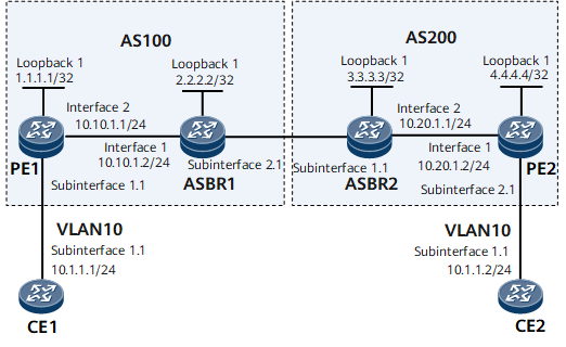
On the network shown in Figure 1, CE1 and CE2 access the MPLS backbone network through PE1 in AS100 and PE2 in AS200, respectively.
Inter-AS LDP VPLS Option A needs to be deployed for CE1 and CE2 to communicate.

Configuration Roadmap
The configuration roadmap is as follows:
Configure an IGP protocol for each AS on the MPLS backbone network to ensure IP connectivity within the same AS and establish an LSP between the PEs.
Configure basic MPLS functions on the MPLS backbone network and establish a dynamic LSP between the PE and ASBR in the same AS. If the PE and ASBR are not directly connected, establish a remote LDP session between them.
Configure a VSI on PE1, ASBR1, ASBR2, and PE2, and bind these VSIs to corresponding AC interfaces.
Data Preparation
To complete the configuration, you need the following data:
MPLS LSR IDs of PEs and ASBRs
IP addresses of CE interfaces connecting to PEs (no IP addresses need to be configured for PE interfaces connecting to CEs)
Data for configuring the IGP
VSI IDs
Procedure
- Configure interface IP addresses.
# Configure CE1.
<HUAWEI> system-view
[~HUAWEI] sysname CE1
[*HUAWEI] commit
[~CE1] interface gigabitethernet 0/1/0
[*CE1-GigabitEthernet0/1/0] undo shutdown
[*CE1-GigabitEthernet0/1/0] quit
[*CE1] interface gigabitethernet 0/1/0.1
[*CE1-GigabitEthernet0/1/0.1] ip address 10.1.1.1 24
[*CE1-GigabitEthernet0/1/0.1] quit
[*CE1] commit
# Configure PE1.
<HUAWEI> system-view
[~HUAWEI] sysname PE1
[*HUAWEI] commit
[~PE1] interface loopback1
[*PE1-Loopback1] ip address 1.1.1.1 32
[*PE1-Loopback1] quit
[*PE1] interface gigabitethernet 0/1/0
[*PE1-GigabitEthernet0/1/0] undo shutdown
[*PE1-GigabitEthernet0/1/0] quit
[*PE1] interface gigabitethernet 0/1/0.1
[*PE1-GigabitEthernet0/1/0.1] quit
[*PE1] interface gigabitethernet 0/1/8
[*PE1-GigabitEthernet0/1/8] undo shutdown
[*PE1-GigabitEthernet0/1/8] ip address 10.10.1.1 24
[*PE1-GigabitEthernet0/1/8] quit
[*PE1] commit
# Configure ASBR1.
<HUAWEI> system-view
[~HUAWEI] sysname ASBR1
[*HUAWEI] commit
[~ASBR1] interface loopback1
[*ASBR1-Loopback1] ip address 2.2.2.2 32
[*ASBR1-Loopback1] quit
[*ASBR1] interface gigabitethernet 0/1/0
[*ASBR1-GigabitEthernet0/1/0] undo shutdown
[*ASBR1-GigabitEthernet0/1/0] ip address 10.10.1.2 24
[*ASBR1-GigabitEthernet0/1/0] quit
[*ASBR1] interface gigabitethernet 0/1/8
[*ASBR1-GigabitEthernet0/1/8] undo shutdown
[*ASBR1-GigabitEthernet0/1/8] quit
[*ASBR1] interface gigabitethernet 0/1/8.1
[*ASBR1-GigabitEthernet0/1/8.1] quit
[*ASBR1] commit
# Configure ASBR2.
<HUAWEI> system-view
[~HUAWEI] sysname ASBR2
[*HUAWEI] commit
[~ASBR2] interface loopback1
[*ASBR2-Loopback1] ip address 3.3.3.3 32
[*ASBR2-Loopback1] quit
[*ASBR2] interface gigabitethernet 0/1/0
[*ASBR2-GigabitEthernet0/1/0] undo shutdown
[*ASBR2-GigabitEthernet0/1/0] quit
[*ASBR2] interface gigabitethernet 0/1/0.1
[*ASBR2-GigabitEthernet0/1/0.1] quit
[*ASBR2] interface gigabitethernet 0/1/8
[*ASBR2-GigabitEthernet0/1/8] undo shutdown
[*ASBR2-GigabitEthernet0/1/8] ip address 10.20.1.1 24
[*ASBR2-GigabitEthernet0/1/8] quit
[*ASBR2] commit
# Configure PE2.
<HUAWEI> system-view
[~HUAWEI] sysname PE2
[*HUAWEI] commit
[~PE2] interface loopback1
[*PE2-Loopback1] ip address 4.4.4.4 32
[*PE2-Loopback1] quit
[*PE2] interface gigabitethernet 0/1/0
[*PE2-GigabitEthernet0/1/0] undo shutdown
[*PE2-GigabitEthernet0/1/0] ip address 10.20.1.2 24
[*PE2-GigabitEthernet0/1/0] quit
[*PE2] interface gigabitethernet 0/1/8
[*PE2-GigabitEthernet0/1/8] undo shutdown
[*PE2-GigabitEthernet0/1/8] quit
[*PE2] interface gigabitethernet 0/1/8.1
[*PE2-GigabitEthernet0/1/8.1] quit
[*PE2] commit
# Configure CE2.
<HUAWEI> system-view
[~HUAWEI] sysname CE2
[*HUAWEI] commit
[~CE2] interface gigabitethernet 0/1/0
[*CE2-GigabitEthernet0/1/0] undo shutdown
[*CE2-GigabitEthernet0/1/0] quit
[*CE2] interface gigabitethernet 0/1/0.1
[*CE2-GigabitEthernet0/1/0.1] ip address 10.1.1.2 24
[*CE2-GigabitEthernet0/1/0.1] quit
[*CE2] commit
- Configure an IGP on the MPLS backbone network.
# Configure PE1.
[~PE1] ospf 1
[*PE1-ospf-1] area 0.0.0.0
[*PE1-ospf-1-area-0.0.0.0] network 1.1.1.1 0.0.0.0
[*PE1-ospf-1-area-0.0.0.0] network 10.10.1.0 0.0.0.255
[*PE1-ospf-1-area-0.0.0.0] quit
[*PE1-ospf-1] quit
[*PE1] commit
# Configure ASBR1.
[~ASBR1] ospf 1
[*ASBR1-ospf-1] area 0.0.0.0
[*ASBR1-ospf-1-area-0.0.0.0] network 2.2.2.2 0.0.0.0
[*ASBR1-ospf-1-area-0.0.0.0] network 10.10.1.0 0.0.0.255
[*ASBR1-ospf-1-area-0.0.0.0] quit
[*ASBR1-ospf-1] quit
[*ASBR1] commit
# Configure ASBR2.
[~ASBR2] ospf 1
[*ASBR2-ospf-1] area 0.0.0.0
[*ASBR2-ospf-1-area-0.0.0.0] network 3.3.3.3 0.0.0.0
[*ASBR2-ospf-1-area-0.0.0.0] network 10.20.1.0 0.0.0.255
[*ASBR2-ospf-1-area-0.0.0.0] quit
[*ASBR2-ospf-1] quit
[*ASBR2] commit
# Configure PE2.
[~PE2] ospf 1
[*PE2-ospf-1] area 0.0.0.0
[*PE2-ospf-1-area-0.0.0.0] network 4.4.4.4 0.0.0.0
[*PE2-ospf-1-area-0.0.0.0] network 10.20.1.0 0.0.0.255
[*PE2-ospf-1-area-0.0.0.0] quit
[*PE2-ospf-1] quit
[*PE2] commit
- Configure basic MPLS functions and establish LSPs.
# Configure PE1.
[~PE1] mpls lsr-id 1.1.1.1
[*PE1] mpls
[*PE1-mpls] quit
[*PE1] mpls ldp
[*PE1-mpls-ldp] quit
[*PE1] inerface gigabitethernet 0/1/8
[*PE1-GigabitEthernet0/1/8] mpls
[*PE1-GigabitEthernet0/1/8] mpls ldp
[*PE1-GigabitEthernet0/1/8] quit
[*PE1] commit
# Configure ASBR1.
[~ASBR1] mpls lsr-id 2.2.2.2
[*ASBR1] mpls
[*ASBR1-mpls] quit
[*ASBR1] mpls ldp
[*ASBR1-mpls-ldp] quit
[*ASBR1] inerface gigabitethernet 0/1/0
[*ASBR1-GigabitEthernet0/1/0] mpls
[*ASBR1-GigabitEthernet0/1/0] mpls ldp
[*ASBR1-GigabitEthernet0/1/0] quit
[*ASBR1] commit
# Configure ASBR2.
[~ASBR2] mpls lsr-id 3.3.3.3
[*ASBR2] mpls
[*ASBR2-mpls] quit
[*ASBR2] mpls ldp
[*ASBR2-mpls-ldp] quit
[*ASBR2] inerface gigabitethernet 0/1/8
[*ASBR2-GigabitEthernet0/1/8] mpls
[*ASBR2-GigabitEthernet0/1/8] mpls ldp
[*ASBR2-GigabitEthernet0/1/8] quit
[*ASBR2] commit
# Configure PE2.
[~PE2] mpls lsr-id 4.4.4.4
[*PE2] mpls
[*PE2-mpls] quit
[*PE2] mpls ldp
[*PE2-mpls-ldp] quit
[*PE2] inerface gigabitethernet 0/1/0
[*PE2-GigabitEthernet0/1/0] mpls
[*PE2-GigabitEthernet0/1/0] mpls ldp
[*PE2-GigabitEthernet0/1/0] quit
[*PE2] commit
- Configure LDP VPLS.
# Configure PE1.
[~PE1] mpls l2vpn
[*PE1-l2vpn] quit
[*PE1] vsi v1
[*PE1-vsi-v1] pwsignal ldp
[*PE1-vsi-v1-ldp] vsi-id 2
[*PE1-vsi-v1-ldp] peer 2.2.2.2
[*PE1-vsi-v1-ldp] quit
[*PE1-vsi-v1] quit
[*PE1] interface gigabitethernet 0/1/0.1
[*PE1-GigabitEthernet0/1/0.1] vlan-type dot1q 10
[*PE1-GigabitEthernet0/1/0.1] l2 binding vsi v1
[*PE1-GigabitEthernet0/1/0.1] quit
[*PE1] commit
# Configure ASBR1.
[~ASBR1] mpls l2vpn
[*ASBR1-l2vpn] quit
[*ASBR1] vsi v1
[*ASBR1-vsi-v1] pwsignal ldp
[*ASBR1-vsi-v1-ldp] vsi-id 2
[*ASBR1-vsi-v1-ldp] peer 1.1.1.1
[*ASBR1-vsi-v1-ldp] quit
[*ASBR1-vsi-v1-ldp] quit
[*ASBR1-vsi-v1] quit
[*ASBR1] interface gigabitethernet 0/1/8.1
[*ASBR1-GigabitEthernet0/1/8.1] vlan-type dot1q 10
[*ASBR1-GigabitEthernet0/1/8.1] l2 binding vsi v1
[*ASBR1-GigabitEthernet0/1/8.1] quit
[*ASBR1] commit
# Configure ASBR2.
[~ASBR2] mpls l2vpn
[*ASBR2-l2vpn] quit
[*ASBR2] vsi v1
[*ASBR2-vsi-v1] pwsignal ldp
[*ASBR2-vsi-v1-ldp] vsi-id 2
[*ASBR2-vsi-v1-ldp] peer 4.4.4.4
[*ASBR2-vsi-v1-ldp] quit
[*ASBR2-vsi-v1] quit
[*ASBR2] interface gigabitethernet 0/1/0.1
[*ASBR2-GigabitEthernet0/1/0.1] vlan-type dot1q 10
[*ASBR2-GigabitEthernet0/1/0.1] l2 binding vsi v1
[*ASBR2-GigabitEthernet0/1/0.1] quit
[*ASBR2] commit
# Configure PE2.
[~PE2] mpls l2vpn
[*PE2-l2vpn] quit
[*PE2] vsi v1
[*PE2-vsi-v1] pwsignal ldp
[*PE2-vsi-v1-ldp] vsi-id 2
[*PE2-vsi-v1-ldp] peer 3.3.3.3
[*PE2-vsi-v1-ldp] quit
[*PE2-vsi-v1] quit
[*PE2] interface gigabitethernet 0/1/8.1
[*PE2-GigabitEthernet0/1/8.1] vlan-type dot1q 10
[*PE2-GigabitEthernet0/1/8.1] l2 binding vsi v1
[*PE2-GigabitEthernet0/1/8.1] quit
[*PE2] commit
- Configure CEs to allow packets from VLAN 10 to pass through.
# Configure CE1.
[~CE1] interface gigabitethernet 0/1/0.1
[*CE1-GigabitEthernet0/1/0.1] vlan-type dot1q 10
[*CE1-GigabitEthernet0/1/0.1] quit
[*CE1] commit
# Configure CE2.
[~CE2] interface gigabitethernet 0/1/0.1
[*CE2-GigabitEthernet0/1/0.1] vlan-type dot1q 10
[*CE2-GigabitEthernet0/1/0.1] quit
[*CE2] commit
- Verify the configuration.
After completing the configurations, run the display vsi name v1 verbose command on PE1 or PE2. The command output shows that VSI State and PW State are both up. The following example uses the command output on PE1.
[~PE1] display vsi name v1 verbose
 ***VSI Name               : v1
    Administrator VSI      : no
    Isolate Spoken         : disable
    VSI Index              : 0
    PW Signaling           : ldp
    Member Discovery Style : static
    Bridge-domain Mode     : disable
    PW MAC Learn Style     : unqualify
    Encapsulation Type     : vlan
    MTU                    : 1500
    Diffserv Mode          : uniform
    Service Class          : --
    Color                  : --
    DomainId               : 255
    Domain Name            :
    Ignore AcState         : disable
    Multicast Fast Swicth  : disable
    Create Time            : 0 days, 3 hours, 30 minutes, 31 seconds
    VSI State              : up
    Resource Status        : --

    VSI ID                 : 2
   *Peer Router ID         : 2.2.2.2
    VC Label               : 23552
    Peer Type              : dynamic
    Session                : up
    Tunnel ID              : 0x2002000
    Broadcast Tunnel ID    : 0x2002000
    CKey                   : 6
    NKey                   : 5
    StpEnable             : 0
    PwIndex                : 0

    Interface Name         : GigabitEthernet0/1/0.1
    State                  : up
    Last Up Time           : 2014-08-15 15:41:59
    Total Up Time          : 0 days, 0 hours, 1 minutes, 2 seconds
   **PW Information:
   *Peer Ip Address        : 2.2.2.2
    PW State               : up
    Local VC Label         : 23552
    Remote VC Label        : 23552
    PW Type                : label
    Tunnel ID              : 0x2002000
    Broadcast Tunnel ID    : 0x2002000
    Ckey                   : 0x6
    Nkey                   : 0x5
    Main PW Token          : 0x2002000
    Slave PW Token         : 0x0
    Tnl Type               : LSP
    OutInterface           : GigabitEthernet0/1/8
    Stp Enable             : 0
    Mac Flapping           : 0
    PW Last Up Time        : 2014-08-15 15:41:59
    PW Total Up Time       : 0 days, 0 hours, 1 minutes, 3 seconds
CE1 and CE2 can ping each other. The following example uses the command output on CE1.
[~CE1] ping 10.1.1.2
  PING 10.1.1.2: 56  data bytes, press CTRL_C to break
    Reply from 10.1.1.2: bytes=56 Sequence=1 ttl=255 time=90 ms
    Reply from 10.1.1.2: bytes=56 Sequence=2 ttl=255 time=77 ms
    Reply from 10.1.1.2: bytes=56 Sequence=3 ttl=255 time=34 ms
    Reply from 10.1.1.2: bytes=56 Sequence=4 ttl=255 time=46 ms
    Reply from 10.1.1.2: bytes=56 Sequence=5 ttl=255 time=94 ms
  --- 10.1.1.2 ping statistics ---
    5 packet(s) transmitted
    5 packet(s) received
    0.00% packet loss
    round-trip min/avg/max = 34/68/94 ms
Configuration Files
CE1 configuration file
#
sysname CE1
#
interface GigabitEthernet0/1/0
 undo shutdown
#
interface GigabitEthernet0/1/0.1
 undo shutdown
 vlan-type dot1q 10
 ip address 10.1.1.1 255.255.255.0
#
return
PE1 configuration file
#
sysname PE1
#
mpls lsr-id 1.1.1.1
mpls
#
mpls l2vpn
#
vsi v1
 pwsignal ldp
  vsi-id 2
  peer 2.2.2.2
#
mpls ldp
#
interface GigabitEthernet0/1/0
 undo shutdown
#
interface GigabitEthernet0/1/0.1
 undo shutdown
 vlan-type dot1q 10
 l2 binding vsi v1
#
interface GigabitEthernet0/1/8
 undo shutdown
 ip address 10.10.1.1 255.255.255.252
 mpls
 mpls ldp
#
interface LoopBack1
 ip address 1.1.1.1 255.255.255.255
#
ospf 1
 area 0.0.0.0
  network 1.1.1.1 0.0.0.0
  network 10.10.1.0 0.0.0.255
#
return
ASBR1 configuration file
#
sysname ASBR1
#
mpls lsr-id 2.2.2.2
mpls
#
mpls l2vpn
#
vsi v1
 pwsignal ldp
  vsi-id 2
  peer 1.1.1.1
#
mpls ldp
#
interface GigabitEthernet0/1/8
 undo shutdown
#
interface GigabitEthernet0/1/8.1
 undo shutdown
 vlan-type dot1q 10
 l2 binding vsi v1
#
interface GigabitEthernet0/1/0
 undo shutdown
 ip address 10.10.1.2 255.255.255.252
 mpls
 mpls ldp
#
interface LoopBack1
 ip address 2.2.2.2 255.255.255.255
#
ospf 1
 area 0.0.0.0
  network 2.2.2.2 0.0.0.0
  network 10.10.1.0 0.0.0.255
#
return
ASBR2 configuration file
#
sysname ASBR2
#
mpls lsr-id 3.3.3.3
mpls
#
mpls l2vpn
#
vsi v1
 pwsignal ldp
  vsi-id 2
  peer 4.4.4.4
#
mpls ldp
#
interface GigabitEthernet0/1/0
 undo shutdown
#
interface GigabitEthernet0/1/0.1
 undo shutdown
 vlan-type dot1q 10
 l2 binding vsi v1
#
interface GigabitEthernet0/1/8
 undo shutdown
 ip address 10.20.1.1 255.255.255.0
 mpls
 mpls ldp
#
interface LoopBack1
 ip address 3.3.3.3 255.255.255.255
#
ospf 1
 area 0.0.0.0
  network 3.3.3.3 0.0.0.0
  network 10.20.1.0 0.0.0.255
#
return
PE2 configuration file
#
sysname PE2
#
mpls lsr-id 4.4.4.4
mpls
#
mpls l2vpn
#
vsi v1
 pwsignal ldp
  vsi-id 2
  peer 3.3.3.3
#
mpls ldp
#
interface GigabitEthernet0/1/8
 undo shutdown
#
interface GigabitEthernet0/1/8.1
 undo shutdown
 vlan-type dot1q 10
 l2 binding vsi v1
#
interface GigabitEthernet0/1/0
 undo shutdown
 ip address 10.20.1.2 255.255.255.252
 mpls
 mpls ldp
#
interface LoopBack1
 ip address 4.4.4.4 255.255.255.255
#
ospf 1
 area 0.0.0.0
  network 4.4.4.4 0.0.0.0
  network 10.20.1.0 0.0.0.255
#
return
CE2 configuration file
#
sysname CE2
#
interface GigabitEthernet0/1/0
 undo shutdown
#
interface GigabitEthernet0/1/0.1
 undo shutdown
 ip address 10.1.1.2 255.255.255.0
#
return