Example for Configuring VPLS Multi-homing
This section provides an example for configuring VPLS multi-homing to prevent routing loops in multi-homing scenarios, when they support BGP signaling.
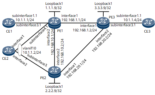
Networking Requirements
To deliver high-reliability services over a VPLS network, carriers usually dual-home a CE to two PEs through redundant links. While providing link-level protection, the dual-homing mechanism also brings in the risk of routing loops. To prevent routing loops in multi-homing scenarios, you can deploy VPLS multi-homing on PEs.
- VPLS multi-homing adjusts link priorities based on the AC status (ACS), multi-homing site priority (PREF), and PE's router ID (PE-ID) in descending order of priority to ensure that one access link of a multi-homed CE is in the active state and the other access links are in the blocked state.
- PEs establish PWs to carry end-to-end services.

Configuration Roadmap
The configuration roadmap is as follows:
Configure an IGP and basic MPLS functions on the backbone network.
Establish an LSP between PEs.
Enable MPLS L2VPN on PEs.
Enable PEs to exchange VPLS information as BGP peers.
Create a VSI on each PE, specify BGP signaling, and specify RDs and VPN targets.
Configure VPLS multi-homing.
Bind AC interfaces to VSIs.
Data Preparation
To complete the configuration, you need the following data:
Peer IP addresses
VSI names on PE1 and PE2
BGP AS numbers on PE1 and PE2
RD and VPN targets of each PE's VSI and CE's MH-ID
Interfaces to which VSIs are bound and VLAN IDs of the interfaces
Procedure
- Assign an IP address to each device interface on the backbone network.
# Configure PE1.
<HUAWEI> system-view
[~HUAWEI] sysname PE1
[*HUAWEI] commit
[~PE1] interface loopback1
[*PE1-Loopback1] ip address 1.1.1.9 32
[*PE1-Loopback1] quit
[*PE1] interface gigabitethernet 0/1/0
[*PE1-GigabitEthernet0/1/0] ip address 192.168.1.1 24
[*PE1-GigabitEthernet0/1/0] quit
[*PE1] interface gigabitethernet 0/1/8
[*PE1-GigabitEthernet0/1/8] ip address 192.168.10.1 24
[*PE1-GigabitEthernet0/1/8] quit
[*PE1] interface gigabitethernet 0/1/16.1
[*PE1-GigabitEthernet0/1/16.1] undo shutdown
[*PE1-GigabitEthernet0/1/16.1] quit
[*PE1] interface gigabitethernet 0/1/24.1
[*PE1-GigabitEthernet0/1/24.1] undo shutdown
[*PE1-GigabitEthernet0/1/24.1] quit
[*PE1] commit
# Configure PE2.
<HUAWEI> system-view
[~HUAWEI] sysname PE2
[*HUAWEI] commit
[~PE2] interface loopback1
[*PE2-Loopback1] ip address 2.2.2.9 32
[*PE2-Loopback1] quit
[*PE2] interface gigabitethernet 0/1/0
[*PE2-GigabitEthernet0/1/0] 192.168.20.1 24
[*PE2-GigabitEthernet0/1/0] quit
[*PE2] interface gigabitethernet 0/1/8
[*PE2-GigabitEthernet0/1/8] 192.168.10.2 24
[*PE2-GigabitEthernet0/1/8] quit
[*PE2] interface gigabitethernet 0/1/16.1
[*PE2-GigabitEthernet0/1/16.1] undo shutdown
[*PE2-GigabitEthernet0/1/16.1] quit
[*PE2] commit
# Configure PE3.
<HUAWEI> system-view
[~HUAWEI] sysname PE3
[*HUAWEI] commit
[~PE3] interface loopback1
[*PE3-Loopback1] ip address 3.3.3.9 32
[*PE3-Loopback1] quit
[*PE3] interface gigabitethernet 0/1/0
[*PE3-GigabitEthernet0/1/0] 192.168.1.2 24
[*PE3-GigabitEthernet0/1/0] quit
[*PE3] interface gigabitethernet 0/1/8
[*PE3-GigabitEthernet0/1/8] 192.168.20.2 24
[*PE3-GigabitEthernet0/1/8] quit
[*PE3] interface gigabitethernet 0/1/16.1
[*PE3-GigabitEthernet0/1/16.1] undo shutdown
[*PE3-GigabitEthernet0/1/16.1] quit
[*PE3] commit
# Configure CE1.
<HUAWEI> system-view
[~HUAWEI] sysname CE1
[*HUAWEI] commit
[~CE1] interface gigabitethernet 0/1/0.1
[*CE1-GigabitEthernet0/1/0.1] undo shutdown
[*CE1-GigabitEthernet0/1/0.1] vlan-type dot1q 10
[*CE1-GigabitEthernet0/1/0.1] ip address 10.1.1.1 24
[*CE1-GigabitEthernet0/1/0.1] quit
[*CE1] commit
# Configure CE2.
<HUAWEI> system-view
[~HUAWEI] sysname CE2
[*HUAWEI] commit
[~CE2] vlan 10
[*CE2-vlan10] quit
[*CE2] interface gigabitethernet 0/1/0
[*CE2-GigabitEthernet0/1/0] portswitch
[*CE2-GigabitEthernet0/1/0] port trunk allow-pass vlan 10
[*CE2-GigabitEthernet0/1/0] quit
[*CE2] interface gigabitethernet 0/1/8
[*CE2-GigabitEthernet0/1/8] portswitch
[*CE2-GigabitEthernet0/1/8] port trunk allow-pass vlan 10
[*CE2-GigabitEthernet0/1/8] quit
[*CE2] interface vlanif10
[*CE2-Vlanif10] ip address 10.1.1.2 24
[*CE2-Vlanif10] quit
[*CE2] commit
# Configure CE3.
<HUAWEI> system-view
[~HUAWEI] sysname CE3
[*HUAWEI] commit
[~CE3] interface gigabitethernet 0/1/0.1
[*CE3-GigabitEthernet0/1/0.1] undo shutdown
[*CE3-GigabitEthernet0/1/0.1] vlan-type dot1q 10
[*CE3-GigabitEthernet0/1/0.1] ip address 10.1.1.4 24
[*CE3-GigabitEthernet0/1/0.1] quit
[*CE3] commit
- Configure an IGP. In this example, OSPF is used.
# Configure PE1.
[~PE1] ospf 1
[*PE1-ospf-1] area 0.0.0.0
[*PE1-ospf-1-area-0.0.0.0] network 1.1.1.9 0.0.0.0
[*PE1-ospf-1-area-0.0.0.0] network 192.168.1.0 0.0.0.255
[*PE1-ospf-1-area-0.0.0.0] network 192.168.10.0 0.0.0.255
[*PE1-ospf-1-area-0.0.0.0] quit
[*PE1-ospf-1] quit
[*PE1] commit
# Configure PE2.
[~PE2] ospf 1
[*PE2-ospf-1] area 0.0.0.0
[*PE2-ospf-1-area-0.0.0.0] network 2.2.2.9 0.0.0.0
[*PE2-ospf-1-area-0.0.0.0] network 192.168.10.0 0.0.0.255
[*PE2-ospf-1-area-0.0.0.0] network 192.168.20.0 0.0.0.255
[*PE2-ospf-1-area-0.0.0.0] quit
[*PE2-ospf-1] quit
[*PE2] commit
# Configure PE3.
[~PE3] ospf 1
[*PE3-ospf-1] area 0.0.0.0
[*PE3-ospf-1-area-0.0.0.0] network 3.3.3.9 0.0.0.0
[*PE3-ospf-1-area-0.0.0.0] network 192.168.1.0 0.0.0.255
[*PE3-ospf-1-area-0.0.0.0] network 192.168.20.0 0.0.0.255
[*PE3-ospf-1-area-0.0.0.0] quit
[*PE3-ospf-1] quit
[*PE3] commit
- Enable MPLS and establish LSPs.
# Configure PE1.
[~PE1] mpls lsr-id 1.1.1.9
[*PE1] mpls
[*PE1-mpls] quit
[*PE1] mpls ldp
[*PE1-mpls-ldp] quit
[*PE1] interface gigabitethernet 0/1/0
[*PE1-GigabitEthernet0/1/0] mpls
[*PE1-GigabitEthernet0/1/0] mpls ldp
[*PE1-GigabitEthernet0/1/0] quit
[*PE1] interface gigabitethernet 0/1/8
[*PE1-GigabitEthernet0/1/8] mpls
[*PE1-GigabitEthernet0/1/8] mpls ldp
[*PE1-GigabitEthernet0/1/8] quit
[*PE1] commit
# Configure PE2.
[~PE2] mpls lsr-id 2.2.2.9
[*PE2] mpls
[*PE2-mpls] quit
[*PE2] mpls ldp
[*PE2-mpls-ldp] quit
[*PE2] interface gigabitethernet 0/1/0
[*PE2-GigabitEthernet0/1/0] mpls
[*PE2-GigabitEthernet0/1/0] mpls ldp
[*PE2-GigabitEthernet0/1/0] quit
[*PE2] interface gigabitethernet 0/1/8
[*PE2-GigabitEthernet0/1/8] mpls
[*PE2-GigabitEthernet0/1/8] mpls ldp
[*PE2-GigabitEthernet0/1/8] quit
[*PE2] commit
# Configure PE3.
[~PE3] mpls lsr-id 3.3.3.9
[*PE3] mpls
[*PE3-mpls] quit
[*PE3] mpls ldp
[*PE3-mpls-ldp] quit
[*PE3] interface gigabitethernet 0/1/0
[*PE3-GigabitEthernet0/1/0] mpls
[*PE3-GigabitEthernet0/1/0] mpls ldp
[*PE3-GigabitEthernet0/1/0] quit
[*PE3] interface gigabitethernet 0/1/8
[*PE3-GigabitEthernet0/1/8] mpls
[*PE3-GigabitEthernet0/1/8] mpls ldp
[*PE3-GigabitEthernet0/1/8] quit
[*PE3] commit
- Enable PEs to exchange VPLS information as BGP peers.
# Configure PE1.
[~PE1] bgp 100
[*PE1-bgp] peer 2.2.2.9 as-number 100
[*PE1-bgp] peer 2.2.2.9 connect-interface loopback1
[*PE1-bgp] peer 3.3.3.9 as-number 100
[*PE1-bgp] peer 3.3.3.9 connect-interface loopback1
[*PE1-bgp] l2vpn-ad-family
[*PE1-bgp-af-l2vpn-ad] signaling vpls
[*PE1-bgp-af-l2vpn-ad] signaling multi-homing non-standard-compatible
[*PE1-bgp-af-l2vpn-ad] peer 2.2.2.9 enable
[*PE1-bgp-af-l2vpn-ad] peer 3.3.3.9 enable
[*PE1-bgp-af-l2vpn-ad] quit
[*PE1-bgp] quit
[*PE1] commit
# Configure PE2.
[~PE2] bgp 100
[*PE2-bgp] peer 1.1.1.9 as-number 100
[*PE2-bgp] peer 1.1.1.9 connect-interface loopback1
[*PE2-bgp] peer 3.3.3.9 as-number 100
[*PE2-bgp] peer 3.3.3.9 connect-interface loopback1
[*PE2-bgp] l2vpn-ad-family
[*PE2-bgp-af-l2vpn-ad] signaling vpls
[*PE2-bgp-af-l2vpn-ad] signaling multi-homing non-standard-compatible
[*PE2-bgp-af-l2vpn-ad] peer 1.1.1.9 enable
[*PE2-bgp-af-l2vpn-ad] peer 3.3.3.9 enable
[*PE2-bgp-af-l2vpn-ad] quit
[*PE2-bgp] quit
[*PE2] commit
# Configure PE3.
[~PE3] bgp 100
[*PE3-bgp] peer 1.1.1.9 as-number 100
[*PE3-bgp] peer 1.1.1.9 connect-interface loopback1
[*PE3-bgp] peer 2.2.2.9 as-number 100
[*PE3-bgp] peer 2.2.2.9 connect-interface loopback1
[*PE3-bgp] l2vpn-ad-family
[*PE3-bgp-af-l2vpn-ad] signaling vpls
[*PE3-bgp-af-l2vpn-ad] signaling multi-homing non-standard-compatible
[*PE3-bgp-af-l2vpn-ad] peer 1.1.1.9 enable
[*PE3-bgp-af-l2vpn-ad] peer 2.2.2.9 enable
[*PE3-bgp-af-l2vpn-ad] quit
[*PE3-bgp] quit
[*PE3] commit
- Enable MPLS L2VPN on PEs.
# Configure PE1.
[~PE1] mpls l2vpn
[*PE1-l2vpn] quit
[*PE1] commit
# Configure PE2.
[~PE2] mpls l2vpn
[*PE2-l2vpn] quit
[*PE2] commit
# Configure PE3.
[~PE3] mpls l2vpn
[*PE3-l2vpn] quit
[*PE3] commit
- Create multi-homing sites and configure VPLS connections.
# Configure PE1.
[~PE1] vsi bgp1
[*PE1-vsi-bgp1] pwsignal bgp multi-homing
[*PE1-vsi-bgp1-bgp] route-distinguisher 192.168.1.1:1
[*PE1-vsi-bgp1-bgp] vpn-target 100:1 import-extcommunity
[*PE1-vsi-bgp1-bgp] vpn-target 100:1 export-extcommunity
[*PE1-vsi-bgp1-bgp] site-range 1000 default-offset 0
[*PE1-vsi-bgp1-bgp] site default
[*PE1-vsi-bgp1-bgp-site-default] site-id 10
[*PE1-vsi-bgp1-bgp-site-site1] quit
[*PE1-vsi-bgp1-bgp] site name site2
[*PE1-vsi-bgp1-bgp-site-site2] site-id 20
[*PE1-vsi-bgp1-bgp-site-site2] quit
[*PE1-vsi-bgp1-bgp] site name best
[*PE1-vsi-bgp1-bgp-site-best] site-id 100
[*PE1-vsi-bgp1-bgp-site-best] best-site
[*PE1-vsi-bgp1-bgp-site-best] quit
[*PE1-vsi-bgp1] quit
[*PE1] commit
# Configure PE2.
[~PE2] vsi bgp1
[*PE2-vsi-bgp1] pwsignal bgp multi-homing
[*PE2-vsi-bgp1-bgp] route-distinguisher 192.168.10.2:1
[*PE2-vsi-bgp1-bgp] vpn-target 100:1 import-extcommunity
[*PE2-vsi-bgp1-bgp] vpn-target 100:1 export-extcommunity
[*PE2-vsi-bgp1-bgp] site-range 1000 default-offset 0
[*PE2-vsi-bgp1-bgp] site name site2
[*PE2-vsi-bgp1-bgp-site-site2] site-id 20
[*PE2-vsi-bgp1-bgp-site-site2] quit
[*PE2-vsi-bgp1-bgp] site name best
[*PE2-vsi-bgp1-bgp-site-best] site-id 200
[*PE2-vsi-bgp1-bgp-site-best] best-site
[*PE2-vsi-bgp1-bgp-site-best] quit
[*PE2-vsi-bgp1-bgp] quit
[*PE2-vsi-bgp1] quit
[*PE2] commit
# Configure PE3.
[~PE3] vsi bgp1
[*PE3-vsi-bgp1] pwsignal bgp multi-homing
[*PE3-vsi-bgp1-bgp] route-distinguisher 192.168.20.2:1
[*PE3-vsi-bgp1-bgp] vpn-target 100:1 import-extcommunity
[*PE3-vsi-bgp1-bgp] vpn-target 100:1 export-extcommunity
[*PE3-vsi-bgp1-bgp] site-range 1000 default-offset 0
[*PE3-vsi-bgp1-bgp] site default
[*PE3-vsi-bgp1-bgp-site-site1] site-id 30
[*PE3-vsi-bgp1-bgp-site-site1] quit
[*PE3-vsi-bgp1-bgp] site name best
[*PE3-vsi-bgp1-bgp-site-best] site-id 300
[*PE3-vsi-bgp1-bgp-site-best] best-site
[*PE3-vsi-bgp1-bgp-site-best] quit
[*PE3-vsi-bgp1-bgp] quit
[*PE3-vsi-bgp1] quit
[*PE3] commit
- Create AC interfaces, configure the AC interfaces to allow packets from VLAN 10 to pass through, and bind multi-homing sites to the AC interfaces.
# Configure PE1.
[~PE1] interface gigabitethernet0/1/16.1
[*PE1-GigabitEthernet0/1/16.1] vlan-type dot1q 10
[*PE1-GigabitEthernet0/1/16.1] l2 binding vsi bgp1 multi-homing-site default
[*PE1-GigabitEthernet0/1/16.1] quit
[*PE1] interface gigabitethernet0/1/24.1
[*PE1-GigabitEthernet0/1/24.1] vlan-type dot1q 10
[*PE1-GigabitEthernet0/1/24.1] l2 binding vsi bgp1 multi-homing-site site2
[*PE1-GigabitEthernet0/1/24.1] quit
[*PE1] commit
# Configure PE2.
[~PE2] interface gigabitethernet0/1/16.1
[*PE2-GigabitEthernet0/1/16.1] vlan-type dot1q 10
[*PE1-GigabitEthernet0/1/16.1] l2 binding vsi bgp1 multi-homing-site site2
[*PE2-GigabitEthernet0/1/16.1] quit
[*PE2] commit
# Configure PE3.
[~PE3] interface gigabitethernet0/1/16.1
[*PE3-GigabitEthernet0/1/16.1] vlan-type dot1q 10
[*PE3-GigabitEthernet0/1/16.1] l2 binding vsi bgp1 multi-homing-site default
[*PE3-GigabitEthernet0/1/16.1] quit
[*PE3] commit
- Verify the configuration.
After completing the configurations, run the display vsi verbose command on PE1 to view VPLS connection information in VPLS multi-homing scenarios.
[~PE1] display vsi verbose
 ***VSI Name               : bgp1
    Work Mode              : normal
    Administrator VSI      : no
    Isolate Spoken         : disable
    VSI Index              : 1
    PW Signaling           : bgpmh
    Member Discovery Style : --
    Bridge-domain Mode     : disable
    PW MAC Learn Style     : unqualify
    Encapsulation Type     : vlan
    MTU                    : 1500
    Diffserv Mode          : uniform
    Service Class          : --
    Color                  : --
    DomainId               : 255
    Domain Name            :
    Ignore AcState         : disable
    P2P VSI                : disable
    Create Time            : 0 days, 3 hours, 58 minutes, 56 seconds
    VSI State              : up
    Resource Status        : --

    BGP RD                 : 192.168.1.1:1
    Import vpn target      : 100:1
    Export vpn target      : 100:1
    Local Label Block      : 0/33176/8/1

    Interface Name         : GigabitEthernet0/1/16.1
    State                  : up
    Ac Block State         : unblocked
    Access Port            : false
    Last Up Time           : 2016/03/31 20:50:42
    Total Up Time          : 0 days, 3 hours, 42 minutes, 15 seconds
    Interface Name         : GigabitEthernet0/1/24.1
    State                  : up
    Ac Block State         : unblocked
    Access Port            : false
    Last Up Time           : 2016/03/31 20:51:47
    Total Up Time          : 0 days, 3 hours, 40 minutes, 43 seconds
# Perform a ping operation from CE1 to CE3. The ping is successful.
[~CE1] ping 10.1.1.4
  PING 10.1.1.4: 56  data bytes, press CTRL_C to break
    Reply from 10.1.1.4: bytes=56 Sequence=1 ttl=255 time=90 ms
    Reply from 10.1.1.4: bytes=56 Sequence=2 ttl=255 time=77 ms
    Reply from 10.1.1.4: bytes=56 Sequence=3 ttl=255 time=34 ms
    Reply from 10.1.1.4: bytes=56 Sequence=4 ttl=255 time=46 ms
    Reply from 10.1.1.4: bytes=56 Sequence=5 ttl=255 time=94 ms
  --- 10.1.1.4 ping statistics ---
    5 packet(s) transmitted
    5 packet(s) received
    0.00% packet loss
    round-trip min/avg/max = 34/68/94 ms
Configuration Files
CE1 configuration file
#
sysname CE1
#
interface GigabitEthernet0/1/0
 undo shutdown
#interface GigabitEthernet0/1/0.1
 vlan-type dot1q 10
 ip address 10.1.1.1 255.255.255.0#
return
CE2 configuration file
#
sysname CE2
#
vlan batch 10
#
interface Vlanif10
 ip address 10.1.1.2 255.255.255.0
#
interface GigabitEthernet0/1/0
 portswitch
 undo shutdown
 port trunk allow-pass vlan 10
#
interface GigabitEthernet0/1/8
 portswitch
 undo shutdown
 port trunk allow-pass vlan 10
#
return
CE3 configuration file
#
sysname CE3
#
interface GigabitEthernet0/1/0
 undo shutdown
#
interface GigabitEthernet0/1/0.1
 vlan-type dot1q 10
 ip address 10.1.1.4 255.255.255.0
#
return
PE1 configuration file
#
sysname PE1
#
mpls lsr-id 1.1.1.9
#
mpls
#
mpls l2vpn
#
vsi bgp1
 pwsignal bgp multi-homing
  route-distinguisher 192.168.1.1:1
  vpn-target 100:1 import-extcommunity
  vpn-target 100:1 export-extcommunity
  site-range 1000 default-offset 0
  site name best
   site-id 100
   best-site
  site default
   site-id 10
  site name site2
   site-id 20
#
mpls ldp
#
interface GigabitEthernet0/1/0
 undo shutdown
 ip address 192.168.1.1 255.255.255.0
 mpls
 mpls ldp
#
interface GigabitEthernet0/1/8
 undo shutdown
 ip address 192.168.10.1 255.255.255.0
 mpls
 mpls ldp
#
interface GigabitEthernet0/1/16
 undo shutdown
#
interface GigabitEthernet0/1/16.1
 vlan-type dot1q 10
 l2 binding vsi bgp1
#
interface GigabitEthernet0/1/24
 undo shutdown
#
interface GigabitEthernet0/1/24.1
 vlan-type dot1q 10
 l2 binding vsi bgp1 multi-homing-site site2
#
interface LoopBack1
 ip address 1.1.1.9 255.255.255.255
#
#
bgp 100
 peer 2.2.2.9 as-number 100
 peer 2.2.2.9 connect-interface LoopBack1
 peer 3.3.3.9 as-number 100
 peer 3.3.3.9 connect-interface LoopBack1
 #
 ipv4-family unicast
  undo synchronization
  peer 2.2.2.9 enable
  peer 3.3.3.9 enable
 #
 l2vpn-ad-family
  policy vpn-target
  signaling vpls
  signaling multi-homing non-standard-compatible
  peer 2.2.2.9 enable
  peer 3.3.3.9 enable
#
ospf 1
 area 0.0.0.0
  network 1.1.1.9 0.0.0.0
  network 192.168.1.0 0.0.0.255
  network 192.168.10.0 0.0.0.255
#
return
PE2 configuration file
#
sysname PE2
#
mpls lsr-id 2.2.2.9
#
mpls
#
mpls l2vpn
#
vsi bgp1
 pwsignal bgp multi-homing
  route-distinguisher 192.168.10.2:1
  vpn-target 100:1 import-extcommunity
  vpn-target 100:1 export-extcommunity
  site-range 1000 default-offset 0
  site name best
   site-id 200
   best-site
  site default
  site name site2
   site-id 20
#
mpls ldp
#
interface GigabitEthernet0/1/0
 undo shutdown
 ip address 192.168.20.1 255.255.255.0
 mpls
 mpls ldp
#
interface GigabitEthernet0/1/8
 undo shutdown
 ip address 192.168.10.2 255.255.255.0
 mpls
 mpls ldp
#
interface GigabitEthernet0/1/16
 undo shutdown
#
interface GigabitEthernet0/1/16.1
 vlan-type dot1q 10
 l2 binding vsi bgp1 multi-homing-site site2
#
interface LoopBack1
 ip address 2.2.2.9 255.255.255.255
#
bgp 100
 peer 1.1.1.9 as-number 100
 peer 1.1.1.9 connect-interface LoopBack1
 peer 3.3.3.9 as-number 100
 peer 3.3.3.9 connect-interface LoopBack1
 #
 ipv4-family unicast
  undo synchronization
  peer 1.1.1.9 enable
  peer 3.3.3.9 enable
 #
 l2vpn-ad-family
  policy vpn-target
  signaling vpls
  signaling multi-homing non-standard-compatible
  peer 1.1.1.9 enable
  peer 3.3.3.9 enable
#
ospf 1
 area 0.0.0.0
  network 2.2.2.9 0.0.0.0
  network 192.168.10.0 0.0.0.255
  network 192.168.20.0 0.0.0.255
#
return
PE3 configuration file
#
sysname PE3
#
mpls lsr-id 3.3.3.9
#
mpls
#
mpls l2vpn
#
vsi bgp1
 pwsignal bgp multi-homing
  route-distinguisher 192.168.20.2:1
  vpn-target 100:1 import-extcommunity
  vpn-target 100:1 export-extcommunity
  site-range 1000 default-offset 0
  site name best
   site-id 300
   best-site
  site default
   site-id 30
#
mpls ldp
#
interface GigabitEthernet0/1/0
 undo shutdown
 ip address 192.168.1.2 255.255.255.0
 mpls
 mpls ldp
#
interface GigabitEthernet0/1/8
 undo shutdown
 ip address 192.168.20.2 255.255.255.0
 mpls
 mpls ldp
#
interface GigabitEthernet0/1/16
 undo shutdown
#
interface GigabitEthernet0/1/16.1
 vlan-type dot1q 10
 l2 binding vsi bgp1
#
interface LoopBack1
 ip address 3.3.3.9 255.255.255.255
#
bgp 100
 peer 1.1.1.9 as-number 100
 peer 1.1.1.9 connect-interface LoopBack1
 peer 2.2.2.9 as-number 100
 peer 2.2.2.9 connect-interface LoopBack1
 #
 ipv4-family unicast
  undo synchronization
  peer 1.1.1.9 enable
  peer 2.2.2.9 enable
 #
 l2vpn-ad-family
  policy vpn-target
  signaling vpls
  signaling multi-homing non-standard-compatible
  peer 1.1.1.9 enable
  peer 2.2.2.9 enable
#
ospf 1
 area 0.0.0.0
  network 3.3.3.9 0.0.0.0
  network 192.168.1.0 0.0.0.255
  network 192.168.20.0 0.0.0.255
#
return