Example for Configuring OAM Mapping
This section provides an example for configuring OAM mapping. When an intermediary such as a switch exists between a PE and a CE, you can configure OAM mapping to associate the OAM status on an AC interface with the PW status.
Networking RequirementsDCN
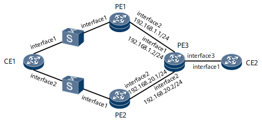
When the AC interface bound to a VPLS changes, a PE sends an LDP MAC-Withdraw message to its peer. As shown in Figure 1, an intermediary exists between CE1 and PE1, and another intermediary exists between CE1 and PE2. When CE1's GE 0/1/0 goes Down, PE1's GE 0/1/0 (AC interface) does not go Down immediately. As a result, PE1 does not immediately send an LDP MAC-Withdraw message to PE3, causing the downstream traffic from PE3 to PE1 to be lost. To prevent this problem, you can configure OAM mapping on CE1, PE1, and PE2 so that OAM monitors the links between the CE and PEs and the OAM status is associated with the PW status. When the CE1's GE 0/1/0 goes Down, a primary/secondary PW switchover is rapidly triggered.

Configuration Roadmap
The configuration roadmap is as follows:
Configure an IGP and basic MPLS functions on the backbone network.
Establish LSPs between the PEs.
Enable MPLS L2VPN on each PE.
Configure an LDP VPLS on each PE.
Configure OAM mapping.
Data Preparation
To complete the configuration, you need the following data:
Peer IP addresses
VSI names on PE1 and PE2
Names and VLAN IDs of the AC interfaces to be bound to VSIs
Procedure
- Assign an IP address to each device interface on the backbone network.
# Configure PE1.
<HUAWEI> system-view
[~HUAWEI] sysname PE1
[*HUAWEI] commit
[~PE1] interface loopback 1
[*PE1-Loopback1] ip address 1.1.1.1 32
[*PE1-Loopback1] quit
[*PE1] interface gigabitethernet 0/1/8
[*PE1-GigabitEthernet0/1/0] ip address 192.168.1.1 24
[*PE1-GigabitEthernet0/1/0] quit
[*PE1] commit
# Configure PE2.
<HUAWEI> system-view
[~HUAWEI] sysname PE2
[*HUAWEI] commit
[~PE2] interface loopback 1
[*PE2-Loopback1] ip address 2.2.2.2 32
[*PE2-Loopback1] quit
[*PE2] interface GigabitEthernet 0/1/8
[*PE2-GigabitEthernet0/1/0] 192.168.20.1 24
[*PE2-GigabitEthernet0/1/0] quit
[*PE2] commit
# Configure PE3.
<HUAWEI> system-view
[~HUAWEI] sysname PE3
[*HUAWEI] commit
[~PE3] interface loopback 1
[*PE3-Loopback1] ip address 3.3.3.3 32
[*PE3-Loopback1] quit
[*PE3] interface GigabitEthernet 0/1/0
[*PE3-GigabitEthernet0/1/0] ip address 192.168.1.2 24
[*PE3-GigabitEthernet0/1/0] quit
[*PE3] interface GigabitEthernet 0/1/8
[*PE3-GigabitEthernet0/1/8] ip address 192.168.20.2 24
[*PE3] commit
# Configure CE1.
[~CE1] vlan 10
[*CE1-vlan10] quit
[*CE1] interface GigabitEthernet 0/1/0
[*CE1-GigabitEthernet0/1/0] portswitch
[*CE1-GigabitEthernet0/1/0] port trunk allow-pass vlan 10
[*CE1-GigabitEthernet0/1/0] quit
[*CE1] interface GigabitEthernet 0/1/8
[*CE1-GigabitEthernet0/1/8] portswitch
[*CE1-GigabitEthernet0/1/8] port trunk allow-pass vlan 10
[*CE1-GigabitEthernet0/1/8] quit
[*CE1] interface vlanif 10
[*CE1-Vlanif10] ip address 10.10.1.1 24
[*CE1-Vlanif10] quit
[*CE1] commit
# Configure CE2.
<HUAWEI> system-view
[~HUAWEI] sysname CE2
[*HUAWEI] commit
[*CE2] interface GigabitEthernet 0/1/0.1
[*CE2-GigabitEthernet0/1/0.1] vlan-type dot1q 10
[*CE2-GigabitEthernet0/1/0.1] ip address 10.10.1.2 24
[*CE2-GigabitEthernet0/1/0.1] quit
[*CE2] commit
- Configure an IGP. In this example, OSPF is used.
# Configure PE1.
[~PE1] ospf 1
[*PE1-ospf-1] area 0.0.0.0
[*PE1-ospf-1-area-0.0.0.0] network 1.1.1.1 0.0.0.0
[*PE1-ospf-1-area-0.0.0.0] network 192.168.1.0 0.0.0.255
[*PE1-ospf-1-area-0.0.0.0] quit
[*PE1-ospf-1] quit
[*PE1] commit
# Configure PE2.
[~PE2] ospf 1
[*PE2-ospf-1] area 0.0.0.0
[*PE2-ospf-1-area-0.0.0.0] network 2.2.2.2 0.0.0.0
[*PE2-ospf-1-area-0.0.0.0] network 192.168.20.0 0.0.0.255
[*PE2-ospf-1-area-0.0.0.0] quit
[*PE2-ospf-1] quit
[*PE2] commit
# Configure PE3.
[~PE3] ospf 1
[*PE3-ospf-1] area 0.0.0.0
[*PE3-ospf-1-area-0.0.0.0] network 3.3.3.3 0.0.0.0
[*PE3-ospf-1-area-0.0.0.0] network 192.168.1.0 0.0.0.255
[*PE3-ospf-1-area-0.0.0.0] network 192.168.20.0 0.0.0.255
[*PE3-ospf-1-area-0.0.0.0] quit
[*PE3-ospf-1] quit
[*PE3] commit
- Configure basic MPLS functions and establish LSPs between the PEs.
# Configure PE1.
[~PE1] mpls lsr-id 1.1.1.1
[*PE1] mpls
[*PE1-mpls] quit
[*PE1] mpls ldp
[*PE1-mpls-ldp] quit
[*PE1] interface GigabitEthernet 0/1/8
[*PE1-GigabitEthernet0/1/8] mpls
[*PE1-GigabitEthernet0/1/8] mpls ldp
[*PE1-GigabitEthernet0/1/8] quit
[*PE1] commit
# Configure PE2.
[~PE2] mpls lsr-id 2.2.2.2
[*PE2] mpls
[*PE2-mpls] quit
[*PE2] mpls ldp
[*PE2-mpls-ldp] quit
[*PE2] interface GigabitEthernet 0/1/8
[*PE2-GigabitEthernet0/1/8] mpls
[*PE2-GigabitEthernet0/1/8] mpls ldp
[*PE2-GigabitEthernet0/1/8] quit
[*PE2] commit
# Configure PE3.
[~PE3] mpls lsr-id 3.3.3.3
[*PE3] mpls
[*PE3-mpls] quit
[*PE3] mpls ldp
[*PE3-mpls-ldp] quit
[*PE3] interface GigabitEthernet 0/1/0
[*PE3-GigabitEthernet0/1/0] mpls
[*PE3-GigabitEthernet0/1/0] mpls ldp
[*PE3-GigabitEthernet0/1/0] quit
[*PE3] interface GigabitEthernet 0/1/8
[*PE3-GigabitEthernet0/1/8] mpls
[*PE3-GigabitEthernet0/1/8] mpls ldp
[*PE3-GigabitEthernet0/1/8] quit
[*PE3] commit
- Enable MPLS L2VPN on each PE.
# Configure PE1.
[~PE1] mpls l2vpn
[*PE1-l2vpn] quit
[*PE1] commit
# Configure PE2.
[~PE2] mpls l2vpn
[*PE2-l2vpn] quit
[*PE2] commit
# Configure PE3.
[~PE3] mpls l2vpn
[*PE3-l2vpn] quit
[*PE3] commit
- Configure an LDP VPLS on each PE.
# Configure PE1.
[~PE1] vsi vsi1
[*PE1-vsi-vsi1] mac-withdraw enable
[*PE1-vsi-vsi1] interface-status-change mac-withdraw enable
[*PE1-vsi-vsi1] pwsignal ldp
[*PE1-vsi-vsi1-ldp] vsi-id 20
[*PE1-vsi-vsi1-ldp] peer 3.3.3.3
[*PE1-vsi-vsi1-ldp] quit
[*PE1-vsi-vsi1] quit
[*PE1] commit
# Configure PE2.
[~PE2] vsi vsi1
[*PE2-vsi-vsi1] mac-withdraw enable
[*PE2-vsi-vsi1] interface-status-change mac-withdraw enable
[*PE2-vsi-vsi1] pwsignal ldp
[*PE2-vsi-vsi1-ldp] vsi-id 20
[*PE2-vsi-vsi1-ldp] peer 3.3.3.3
[*PE2-vsi-vsi1-ldp] quit
[*PE2-vsi-vsi1] quit
[*PE2] commit
# Configure PE3.
[~PE3] vsi vsi1
[*PE3-vsi-vsi1] mac-withdraw enable
[*PE3-vsi-vsi1] interface-status-change mac-withdraw enable
[*PE3-vsi-vsi1] pwsignal ldp
[*PE3-vsi-vsi1-ldp] vsi-id 20
[*PE3-vsi-vsi1-ldp] peer 1.1.1.1
[*PE3-vsi-vsi1-ldp] peer 2.2.2.2 secondary
[*PE3-vsi-vsi1-ldp] quit
[*PE3-vsi-vsi1] quit
[*PE3] commit
- Create a sub-interface and bind it to the VSI on each PE.
# Create a sub-interface on PE1 and bind it to the VSI.
[~PE1] interface GigabitEthernet 0/1/0.1
[*PE1-GigabitEthernet0/1/0.1] vlan-type dot1q 10
[*PE1-GigabitEthernet0/1/0.1] l2 binding vsi vsi1
[*PE1-GigabitEthernet0/1/0.1] quit
[*PE1] commit
# Create a sub-interface on PE2 and bind it to the VSI.
[~PE2] interface GigabitEthernet 0/1/0.1
[*PE2-GigabitEthernet0/1/0.1] vlan-type dot1q 10
[*PE2-GigabitEthernet0/1/0.1] l2 binding vsi vsi1
[*PE2-GigabitEthernet0/1/0.1] quit
[*PE2] commit
# Create a sub-interface on PE3 and bind it to the VSI.
[~PE3] interface GigabitEthernet0/1/16.1
[*PE3-GigabitEthernet0/1/0.1] vlan-type dot1q 10
[*PE3-GigabitEthernet0/1/16.1] l2 binding vsi vsi1
[*PE3-GigabitEthernet0/1/16.1] quit
[*PE3] commit
- Configure OAM mapping.
# Configure CE1.
[~CE1] cfm enable
[*CE1] cfm trigger vlan 10 mac-renew
[*CE1] cfm md md1
[*CE1-md-md1] ma ma1
[*CE1-md-md1-ma-ma1] map vlan 10
[*CE1-md-md1-ma-ma1] mep mep-id 1 interface GigabitEthernet 0/1/0 outward
[*CE1-md-md1-ma-ma1] mep ccm-send mep-id 1 enable
[*CE1-md-md1-ma-ma1] remote-mep mep-id 2
[*CE1-md-md1-ma-ma1] remote-mep ccm-receive mep-id 2 enable
[*CE1-md-md1-ma-ma1] quit
[*CE1-md-md1] ma ma2
[*CE1-md-md1-ma-ma2] mep mep-id 3 interface GigabitEthernet 0/1/8 outward
[*CE1-md-md1-ma-ma2] mep ccm-send mep-id 3 enable
[*CE1-md-md1-ma-ma2] remote-mep mep-id 4
[*CE1-md-md1-ma-ma2] remote-mep ccm-receive mep-id 4 enable
[*CE1-md-md1-ma-ma2] quit
[*CE1-md-md1] quit
[*CE1] commit
# Configure PE1.
[~PE1] cfm enable
[*PE1] cfm md md1
[*PE1-md-md1] ma ma1
[*PE1-md-md1-ma-ma2] map vsi vsi1
[*PE1-md-md1-ma-ma1] mep mep-id 2 interface GigabitEthernet 0/1/0.1 outward
[*PE1-md-md1-ma-ma1] mep ccm-send mep-id 2 enable
[*PE1-md-md1-ma-ma1] remote-mep mep-id 1
[*PE1-md-md1-ma-ma1] remote-mep ccm-receive mep-id 1 enable
[*PE1-md-md1-ma-ma1] quit
[*PE1-md-md1] quit
[*PE2] interface GigabitEthernet 0/1/0.1
[*PE1-GigabitEthernet0/1/0.1] mpls l2vpn oam-mapping 1ag md md1 ma ma1
[*PE1-GigabitEthernet0/1/0.1] quit
[*PE1] commit
# Configure PE2.
[~PE2] cfm enable
[*PE2] cfm md md1
[*PE2-md-md1] ma ma2
[*PE2-md-md1-ma-ma2] map vsi vsi1
[*PE2-md-md1-ma-ma2] mep mep-id 4 interface GigabitEthernet 0/1/0.1 outward
[*PE2-md-md1-ma-ma2] mep ccm-send mep-id 4 enable
[*PE2-md-md1-ma-ma2] remote-mep mep-id 3
[*PE2-md-md1-ma-ma2] remote-mep ccm-receive mep-id 3 enable
[*PE2-md-md1-ma-ma2] quit
[*PE2-md-md1] quit
[*PE2] interface GigabitEthernet 0/1/0.1
[*PE2-GigabitEthernet0/1/0.1] mpls l2vpn oam-mapping 1ag md md1 ma ma2
[*PE2-GigabitEthernet0/1/0.1] quit
[*PE2] commit
- Verify the configuration.
# After completing the configurations, run the display vsi verbose command on PE1 to view the VPLS connection status. The following command output shows that the VPLS is Up.
[~PE1] display vsi verbose
 ***VSI Name               : 1
    Work Mode              : normal
    Administrator VSI      : no
    Isolate Spoken         : disable
    VSI Index              : 1
    PW Signaling           : ldp
    Member Discovery Style : -
    Bridge-domain Mode     : disable
    PW MAC Learn Style     : unqualify
    Encapsulation Type     : vlan
    MTU                    : 1500
    Diffserv Mode          : uniform
    Service Class          : -
    Color                  : -
    DomainId               : 255
    Domain Name            :
    Ignore AcState         : disable
    P2P VSI                : disable
    VSI MAC-WITHDRAW       : Interface-status-change Enable
                           : mac-withdraw Enable
    Multicast Fast Switch  : disable
    Create Time            : 0 days, 2 hours, 51 minutes, 10 seconds
    VSI State              : up
    Resource Status        : -

    VSI ID                 : 20
   *Peer Router ID         : 3.3.3.3
    Negotiation-vc-id      : 20
    primary or secondary   : primary
    ignore-standby-state   : no
    VC Label               : 32828
    Peer Type              : dynamic
    Session                : up
    Tunnel ID              : 0x0000000001004c4b42
    Broadcast Tunnel ID    : -
    Broad BackupTunnel ID  : -
    CKey                   : 1
    NKey                   : 4076863613
    Stp Enable             : 0
    PwIndex                : 1
    Control Word           : disable

    Interface Name         : GigabitEthernet0/1/0.1
    State                  : up
    AC OAM State           : up
    Access Port            : false
    Last Up Time           : 2017/03/02 07:29:29
    Total Up Time          : 0 days, 2 hours, 41 minutes, 17 seconds

  **PW Information:

   *Peer Ip Address        : 3.3.3.3
    PW State               : up
    Local VC Label         : 32828
    Remote VC Label        : 33008
    Remote Control Word    : disable
    PW Type                : label
    Local  VCCV            : alert lsp-ping
    Remote VCCV            : alert lsp-ping
    Tunnel ID              : 0x0000000001004c4b42
    Broadcast Tunnel ID    : -
    Broad BackupTunnel ID  : -
    Ckey                   : 1
    Nkey                   : 4076863613
    Main PW Token          : 0x0
    Slave PW Token         : 0x0
    Tnl Type               : ldp
    OutInterface           : -
    Backup OutInterface    : -
    Stp Enable             : 0
    Mac Flapping           : 0
    PW Last Up Time        : 2017/03/02 07:53:41
    PW Total Up Time       : 0 days, 2 hours, 17 minutes, 4 seconds
# Enable CE1 to ping CE2. The following command output shows that CE1 can ping through CE2's address (10.10.1.2).
[~CE1] ping 10.10.1.2
PING 10.10.1.2: 56  data bytes, press CTRL_C to break
    Reply from 10.10.1.2: bytes=56 Sequence=1 ttl=255 time=31 ms
    Reply from 10.10.1.2: bytes=56 Sequence=2 ttl=255 time=2 ms
    Reply from 10.10.1.2: bytes=56 Sequence=3 ttl=255 time=2 ms
    Reply from 10.10.1.2: bytes=56 Sequence=4 ttl=255 time=2 ms
    Reply from 10.10.1.2: bytes=56 Sequence=5 ttl=255 time=2 ms

  -- 10.10.1.2 ping statistics --
    5 packet(s) transmitted
    5 packet(s) received
    0.00% packet loss
    round-trip min/avg/max = 2/7/31 ms
Configuration Files
CE1 configuration file
#
sysname CE1
#
vlan batch 10
#
cfm enable
cfm trigger vlan 10 mac-renew
#
interface Vlanif10
 ip address 10.10.1.1 255.255.255.0
#
interface GigabitEthernet0/1/0
 portswitch
 undo shutdown
 port trunk allow-pass vlan 10
 #
interface GigabitEthernet0/1/8
 portswitch
 undo shutdown
 port trunk allow-pass vlan 10
#
cfm md md1
 ma ma1
  map vlan 10
  mep mep-id 1 interface GigabitEthernet0/1/0 outward
  mep ccm-send mep-id 1 enable
  remote-mep mep-id 2
  remote-mep ccm-receive mep-id 2 enable
 ma ma2
  map vlan 10
  mep mep-id 3 interface GigabitEthernet0/1/8 outward
  mep ccm-send mep-id 3 enable
  remote-mep mep-id 4
  remote-mep ccm-receive mep-id 4 enable
#
return
CE2 configuration file
#
sysname CE2
#
interface GigabitEthernet0/1/0.1
 vlan-type dot1q 10
 ip address 10.10.1.2 255.255.255.0
#
return
PE1 configuration file
#
sysname PE1
#
cfm enable
#
mpls lsr-id 1.1.1.1
#
mpls
#
mpls l2vpn
#
vsi vsi1
 mac-withdraw enable
 interface-status-change mac-withdraw enable
 pwsignal ldp
  vsi-id 20
  peer 3.3.3.3
#
mpls ldp
#
interface GigabitEthernet0/1/0
 undo shutdown
#
interface GigabitEthernet0/1/0.1
 vlan-type dot1q 10
 l2 binding vsi vsi1
 mpls l2vpn oam-mapping 1ag md md1 ma ma1
#
interface GigabitEthernet0/1/8
 undo shutdown
 ip address 192.168.1.1 255.255.255.0
 mpls
 mpls ldp
#
interface LoopBack1
 ip address 1.1.1.1 255.255.255.255
#
ospf 1
 area 0.0.0.0
  network 1.1.1.1 0.0.0.0
  network 192.168.1.0 0.0.0.255
#
cfm md md1
 ma ma1
  map vsi vsi1
  mep mep-id 2 interface GigabitEthernet0/1/0.1 outward
  mep ccm-send mep-id 2 enable
  remote-mep mep-id 1
  remote-mep ccm-receive mep-id 1 enable
#
return
PE2 configuration file
#
sysname PE2
#
cfm enable
#
mpls lsr-id 2.2.2.2
#
mpls
#
mpls l2vpn
#
vsi vsi1
 mac-withdraw enable
 interface-status-change mac-withdraw enable
 pwsignal ldp
  vsi-id 20
  peer 3.3.3.3
#
mpls ldp
#
interface GigabitEthernet0/1/0
 undo shutdown
#
interface GigabitEthernet0/1/0.1
 vlan-type dot1q 10
 l2 binding vsi vsi1
 mpls l2vpn oam-mapping 1ag md md1 ma ma2
#
interface GigabitEthernet0/1/8
 undo shutdown
 ip address 192.168.20.1 255.255.255.0
 mpls
 mpls ldp
#
interface LoopBack1
 ip address 2.2.2.2 255.255.255.255
#
ospf 1
 area 0.0.0.0
  network 2.2.2.2 0.0.0.0
  network 192.168.20.0 0.0.0.255
#
cfm md md1
 ma ma2
  map vsi vsi1
  mep mep-id 4 interface GigabitEthernet0/1/0.1 outward
  mep ccm-send mep-id 4 enable
  remote-mep mep-id 3
  remote-mep ccm-receive mep-id 3 enable
#
return
PE3 configuration file
#
sysname PE3
#
mpls lsr-id 3.3.3.3
#
mpls
#
mpls l2vpn
#
vsi vsi1
 mac-withdraw enable
 interface-status-change mac-withdraw enable
 pwsignal ldp
  vsi-id 20
  peer 1.1.1.1
  peer 2.2.2.2 secondary
#
mpls ldp
#
interface GigabitEthernet0/1/16
 undo shutdown
#
interface GigabitEthernet0/1/16.1
 vlan-type dot1q 10
 l2 binding vsi vsi1
#
interface GigabitEthernet0/1/0
 undo shutdown
 ip address 192.168.1.2 255.255.255.0
 mpls
 mpls ldp
#
interface GigabitEthernet0/1/8
 undo shutdown
 ip address 192.168.20.2 255.255.255.0
 mpls
 mpls ldp
#
interface LoopBack1
 ip address 3.3.3.3 255.255.255.255
#
ospf 1
 area 0.0.0.0
  network 3.3.3.3 0.0.0.0
  network 192.168.1.0 0.0.0.255
  network 192.168.20.0 0.0.0.255
#
return