Example for Configuring Inter-AS BGP AD VPLS Option A
Inter-AS BGP AD VPLS Option A is recommended for scenarios where few inter-AS VPLS PWs are required.
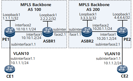
Networking Requirements
On the network shown in Figure 1, CE1 and CE2 access the MPLS backbone network through PE1 in AS100 and PE2 in AS200, respectively.
Inter-AS BGP AD VPLS Option A needs to be deployed for CE1 and CE2 to communicate.

Configuration Roadmap
The configuration roadmap is as follows:
Configure an IGP protocol for each AS on the MPLS backbone network to ensure IP connectivity within the same AS and establish an LSP between the PEs.
Establish an MP-IBGP peer relationship between the ASBR and PE in the same AS.
Configure a VSI on PE1, ASBR1, ASBR2, and PE2, and bind these VSIs to corresponding AC interfaces.
Data Preparation
To complete the configuration, you need the following data:
MPLS LSR IDs of PEs and ASBRs
CE IDs and CE ranges
IP addresses of CE interfaces connecting to PEs (no IP addresses need to be configured for PE interfaces connecting to CEs)
RDs, VPN targets, and site IDs of VSIs
Procedure
- Configure interface IP addresses.
# Configure CE1.
<HUAWEI> system-view
[~HUAWEI] sysname CE1
[*HUAWEI] commit
[*CE1] interface gigabitethernet 0/1/0.1
[*CE1-GigabitEthernet0/1/0.1] ip address 10.1.1.1 24
[*CE1-GigabitEthernet0/1/0.1] quit
[*CE1] commit
# Configure PE1.
<HUAWEI> system-view
[~HUAWEI] sysname PE1
[*HUAWEI] commit
[~PE1] interface loopback1
[*PE1-Loopback1] ip address 1.1.1.1 32
[*PE1-Loopback1] quit
[*PE1] interface gigabitethernet 0/1/8
[*PE1-GigabitEthernet0/1/8] ip address 10.10.1.1 24
[*PE1-GigabitEthernet0/1/8] quit
[*PE1] commit
# Configure ASBR1.
<HUAWEI> system-view
[~HUAWEI] sysname ASBR1
[*HUAWEI] commit
[~ASBR1] interface loopback1
[*ASBR1-Loopback1] ip address 2.2.2.2 32
[*ASBR1-Loopback1] quit
[*ASBR1] interface gigabitethernet 0/1/0
[*ASBR1-GigabitEthernet0/1/0] ip address 10.10.1.2 24
[*ASBR1-GigabitEthernet0/1/0] quit
[*ASBR1] commit
# Configure ASBR2.
<HUAWEI> system-view
[~HUAWEI] sysname ASBR2
[*HUAWEI] commit
[~ASBR2] interface loopback1
[*ASBR2-Loopback1] ip address 3.3.3.3 32
[*ASBR2-Loopback1] quit
[*ASBR2] interface gigabitethernet 0/1/8
[*ASBR2-GigabitEthernet0/1/8] ip address 10.20.1.1 24
[*ASBR2-GigabitEthernet0/1/8] quit
[*ASBR2] commit
# Configure PE2.
<HUAWEI> system-view
[~HUAWEI] sysname PE2
[*HUAWEI] commit
[~PE2] interface loopback1
[*PE2-Loopback1] ip address 4.4.4.4 32
[*PE2-Loopback1] quit
[*PE2] interface gigabitethernet 0/1/0
[*PE2-GigabitEthernet0/1/0] ip address 10.20.1.2 24
[*PE2-GigabitEthernet0/1/0] quit
[*PE2] commit
# Configure CE2.
<HUAWEI> system-view
[~HUAWEI] sysname CE2
[~HUAWEI] commit
[*CE2] interface gigabitethernet 0/1/0.1
[*CE2-GigabitEthernet0/1/0.1] ip address 10.1.1.2 24
[*CE2-GigabitEthernet0/1/0.1] quit
[*CE2] commit
- Configure an IGP on the MPLS backbone network.
# Configure PE1.
[~PE1] ospf 1
[*PE1-ospf-1] area 0.0.0.0
[*PE1-ospf-1-area-0.0.0.0] network 1.1.1.1 0.0.0.0
[*PE1-ospf-1-area-0.0.0.0] network 10.10.1.0 0.0.0.255
[*PE1-ospf-1-area-0.0.0.0] quit
[*PE1-ospf-1] quit
[*PE1] commit
# Configure ASBR1.
[~ASBR1] ospf 1
[*ASBR1-ospf-1] area 0.0.0.0
[*ASBR1-ospf-1-area-0.0.0.0] network 2.2.2.2 0.0.0.0
[*ASBR1-ospf-1-area-0.0.0.0] network 10.10.1.0 0.0.0.255
[*ASBR1-ospf-1-area-0.0.0.0] quit
[*ASBR1-ospf-1] quit
[*ASBR1] commit
# Configure ASBR2.
[~ASBR2] ospf 1
[*ASBR2-ospf-1] area 0.0.0.0
[*ASBR2-ospf-1-area-0.0.0.0] network 3.3.3.3 0.0.0.0
[*ASBR2-ospf-1-area-0.0.0.0] network 10.20.1.0 0.0.0.255
[*ASBR2-ospf-1-area-0.0.0.0] quit
[*ASBR2-ospf-1] quit
[*ASBR2] commit
# Configure PE2.
[~PE2] ospf 1
[*PE2-ospf-1] area 0.0.0.0
[*PE2-ospf-1-area-0.0.0.0] network 4.4.4.4 0.0.0.0
[*PE2-ospf-1-area-0.0.0.0] network 10.20.1.0 0.0.0.255
[*PE2-ospf-1-area-0.0.0.0] quit
[*PE2-ospf-1] quit
[*PE2] commit
- Configure basic MPLS functions and establish LSPs.
# Configure PE1.
[~PE1] mpls lsr-id 1.1.1.1
[*PE1] mpls
[*PE1-mpls] quit
[*PE1] mpls ldp
[*PE1-mpls-ldp] quit
[*PE1] inerface gigabitethernet 0/1/8
[*PE1-GigabitEthernet0/1/8] mpls
[*PE1-GigabitEthernet0/1/8] mpls ldp
[*PE1-GigabitEthernet0/1/8] quit
[*PE1] commit
# Configure ASBR1.
[~ASBR1] mpls lsr-id 2.2.2.2
[*ASBR1] mpls
[*ASBR1-mpls] quit
[*ASBR1] mpls ldp
[*ASBR1-mpls-ldp] quit
[*ASBR1] inerface gigabitethernet 0/1/0
[*ASBR1-GigabitEthernet0/1/0] mpls
[*ASBR1-GigabitEthernet0/1/0] mpls ldp
[*ASBR1-GigabitEthernet0/1/0] quit
[*ASBR1] commit
# Configure ASBR2.
[~ASBR2] mpls lsr-id 3.3.3.3
[*ASBR2] mpls
[*ASBR2-mpls] quit
[*ASBR2] mpls ldp
[*ASBR2-mpls-ldp] quit
[*ASBR2] inerface gigabitethernet 0/1/8
[*ASBR2-GigabitEthernet0/1/8] mpls
[*ASBR2-GigabitEthernet0/1/8] mpls ldp
[*ASBR2-GigabitEthernet0/1/8] quit
[*ASBR2] commit
# Configure PE2.
[~PE2] mpls lsr-id 4.4.4.4
[*PE2] mpls
[*PE2-mpls] quit
[*PE2] mpls ldp
[*PE2-mpls-ldp] quit
[*PE2] inerface gigabitethernet 0/1/0
[*PE2-GigabitEthernet0/1/0] mpls
[*PE2-GigabitEthernet0/1/0] mpls ldp
[*PE2-GigabitEthernet0/1/0] quit
[*PE2] commit
- Establish an MP-IBGP peer relationship between the ASBR and PE in the same AS.
# Configure PE1.
[~PE1] bgp 100
[*PE1-bgp] peer 2.2.2.2 as-number 100
[*PE1-bgp] peer 2.2.2.2 connect-interface loopback 1
[*PE1-bgp] l2vpn-ad-family
[*PE1-bgp-af-l2vpn-ad] peer 2.2.2.2 enable
[*PE1-bgp-af-l2vpn-ad] quit
[*PE1-bgp] quit
[*PE1] commit
# Configure ASBR1.
[~ASBR1] bgp 100
[*ASBR1-bgp] peer 1.1.1.1 as-number 100
[*ASBR1-bgp] peer 1.1.1.1 connect-interface loopback 1
[*ASBR1-bgp] l2vpn-ad-family
[*ASBR1-bgp-af-l2vpn-ad] peer 1.1.1.1 enable
[*ASBR1-bgp-af-l2vpn-ad] quit
[*ASBR1-bgp] quit
[*ASBR1] commit
# Configure ASBR2.
[~ASBR2] bgp 200
[*ASBR2-bgp] peer 4.4.4.4 as-number 200
[*ASBR2-bgp] peer 4.4.4.4 connect-interface loopback 1
[*ASBR2-bgp] l2vpn-ad-family
[*ASBR2-bgp-af-l2vpn-ad] peer 4.4.4.4 enable
[*ASBR2-bgp-af-l2vpn-ad] quit
[*ASBR2-bgp] quit
[*ASBR2] commit
# Configure PE2.
[~PE2] bgp 200
[*PE2-bgp] peer 3.3.3.3 as-number 200
[*PE2-bgp] peer 3.3.3.3 connect-interface loopback 1
[*PE2-bgp] l2vpn-ad-family
[*PE2-bgp-af-l2vpn-ad] peer 3.3.3.3 enable
[*PE2-bgp-af-l2vpn-ad] quit
[*PE2-bgp] quit
[*PE2] commit
After completing the configurations, run the display bgp l2vpn-ad peer command on each PE or ASBR. The command output shows that the MP-IBGP peer relationship status is Established. The following example uses the command output on PE1.
[~PE1] display bgp l2vpn-ad peer BGP local router ID : 10.10.1.1 Local AS number : 100 Total number of peers : 1 Peers in established state : 1 Peer V AS MsgRcvd MsgSent OutQ Up/Down State PrefRcv 2.2.2.2 4 100 97 97 0 01:18:54 Established 1 - Configure BGP AD VPLS.
# Configure PE1.
[~PE1] mpls l2vpn
[*PE1] quit
[*PE1] vsi vplsad1
[*PE1-vsi-vplsad1] bgp-ad
[*PE1-vsi-vplsad1-bgpad] vpls-id 100:1
[*PE1-vsi-vplsad1-bgpad] vpn-target 200:1 import-extcommunity
[*PE1-vsi-vplsad1-bgpad] vpn-target 200:1 export-extcommunity
[*PE1-vsi-vplsad1-bgpad] quit
[*PE1-vsi-vplsad1] quit
[*PE1] interface gigabitethernet0/1/0.1
[*PE1-GigabitEthernet0/1/0.1] vlan-type dot1q 10
[*PE1-GigabitEthernet0/1/0.1] l2 binding vsi vplsad1
[*PE1-GigabitEthernet0/1/0.1] quit
[*PE1] commit
# Configure ASBR1.
[~ASBR1] mpls l2vpn
[*ASBR1] quit
[*ASBR1] vsi vplsad1
[*ASBR1-vsi-vplsad1] bgp-ad
[*ASBR1-vsi-vplsad1-bgpad] vpls-id 100:1
[*ASBR1-vsi-vplsad1-bgpad] vpn-target 200:1 import-extcommunity
[*ASBR1-vsi-vplsad1-bgpad] vpn-target 200:1 export-extcommunity
[*ASBR1-vsi-vplsad1-bgpad] quit
[*ASBR1-vsi-vplsad1] quit
[*ASBR1] interface gigabitethernet0/1/8.1
[*ASBR1-GigabitEthernet0/1/8.1] vlan-type dot1q 10
[*ASBR1-GigabitEthernet0/1/8.1] l2 binding vsi vplsad1
[*ASBR1-GigabitEthernet0/1/8.1] quit
[*ASBR1] commit
# Configure ASBR2.
[~ASBR2] mpls l2vpn
[*ASBR2] quit
[*ASBR2] vsi vplsad1
[*ASBR2-vsi-vplsad1] bgp-ad
[*ASBR2-vsi-vplsad1-bgpad] vpls-id 100:1
[*ASBR2-vsi-vplsad1-bgpad] vpn-target 200:1 import-extcommunity
[*ASBR2-vsi-vplsad1-bgpad] vpn-target 200:1 export-extcommunity
[*ASBR2-vsi-vplsad1-bgpad] quit
[*ASBR2-vsi-vplsad1] quit
[*ASBR2] interface gigabitethernet0/1/0.1
[*ASBR2-GigabitEthernet0/1/0.1] vlan-type dot1q 10
[*ASBR2-GigabitEthernet0/1/0.1] l2 binding vsi vplsad1
[*ASBR2-GigabitEthernet0/1/0.1] quit
[*ASBR2] commit
# Configure PE2.
[*PE2] mpls l2vpn
[*PE2] quit
[*PE2] vsi vplsad1
[*PE2-vsi-vplsad1] bgp-ad
[*PE2-vsi-vplsad1-bgpad] vpls-id 100:1
[*PE2-vsi-vplsad1-bgpad] vpn-target 200:1 import-extcommunity
[*PE2-vsi-vplsad1-bgpad] vpn-target 200:1 export-extcommunity
[*PE2-vsi-vplsad1-bgpad] quit
[*PE2-vsi-vplsad1] quit
[~PE2] interface gigabitethernet0/1/8.1
[*PE2-GigabitEthernet0/1/8.1] vlan-type dot1q 10
[*PE2-GigabitEthernet0/1/8.1] l2 binding vsi vplsad1
[*PE2-GigabitEthernet0/1/8.1] quit
[*PE2] commit
- Configure CEs to allow packets from VLAN 10 to pass through.
# Configure CE1.
[~CE1] interface gigabitethernet0/1/0.1
[*CE1-GigabitEthernet0/1/0.1] vlan-type dot1q 10
[*CE1-GigabitEthernet0/1/0.1] quit
[*CE1] commit
# Configure CE2.
[~CE2] interface gigabitethernet0/1/0.1
[*CE2-GigabitEthernet0/1/0.1] vlan-type dot1q 10
[*CE2-GigabitEthernet0/1/0.1] quit
[*CE2] commit
After completing the configurations, run the display vsi command on each PE or ASBR. The command output shows that the VSI status is up. The following example uses the command output on PE1.
[~PE1] display vsi Total VSI number is 1, 1 is up, 0 is down, 0 is LDP mode, 0 is BGP mode, 1 is BGPAD mode, 0 is mixed mode, 0 is unspecified mode -------------------------------------------------------------------------- Vsi Mem PW Mac Encap Mtu Vsi Name Disc Type Learn Type Value State -------------------------------------------------------------------------- bgpad1 -- bgpad unqualify vlan 1500 up - Verify the configuration.
After the preceding configurations are complete, CE1 and CE2 can ping each other. The following example uses the command output on CE1.
[~CE1] ping 10.1.1.2
  PING 10.1.1.2: 56  data bytes, press CTRL_C to break
    Reply from 10.1.1.2: bytes=56 Sequence=1 ttl=255 time=8 ms
    Reply from 10.1.1.2: bytes=56 Sequence=2 ttl=255 time=3 ms
    Reply from 10.1.1.2: bytes=56 Sequence=3 ttl=255 time=3 ms
    Reply from 10.1.1.2: bytes=56 Sequence=4 ttl=255 time=3 ms
    Reply from 10.1.1.2: bytes=56 Sequence=5 ttl=255 time=4 ms

  --- 10.1.1.2 ping statistics ---
    5 packet(s) transmitted
    5 packet(s) received
    0.00% packet loss
    round-trip min/avg/max = 3/4/8 ms
Configuration Files
CE1 configuration file
#
sysname CE1
#
interface GigabitEthernet0/1/0
 undo shutdown
#
interface GigabitEthernet0/1/0.1
 undo shutdown
 vlan-type dot1q 10
 ip address 10.1.1.1 255.255.255.0
#
return
PE1 configuration file
#
sysname PE1
#
mpls lsr-id 1.1.1.1
#
mpls
#
mpls l2vpn
#
vsi bgpad1
 bgp-ad
  vpls-id 100:1
  vpn-target 200:1 import-extcommunity
  vpn-target 200:1 export-extcommunity
#
mpls ldp
#
interface GigabitEthernet0/1/0
 undo shutdown
#
interface GigabitEthernet0/1/0.1
 vlan-type dot1q 10
 l2 binding vsi bgpad1
#
interface GigabitEthernet0/1/8
 undo shutdown
 ip address 10.10.1.1 255.255.255.0
 mpls
 mpls ldp
#
interface LoopBack1
 ip address 1.1.1.1 255.255.255.255
#
bgp 100
 peer 2.2.2.2 as-number 100
 peer 2.2.2.2 connect-interface LoopBack1
 #
 ipv4-family unicast
  undo synchronization
  peer 2.2.2.2 enable
 #
 l2vpn-ad-family
  policy vpn-target
  peer 2.2.2.2 enable
#
ospf 1
 area 0.0.0.0
  network 1.1.1.1 0.0.0.0
  network 10.10.1.0 0.0.0.255
#
return
ASBR1 configuration file
#
sysname ASBR1
#
mpls lsr-id 2.2.2.2
#
mpls
#
mpls l2vpn
#
vsi bgpad1
 bgp-ad
  vpls-id 100:1
  vpn-target 200:1 import-extcommunity
  vpn-target 200:1 export-extcommunity
#
mpls ldp
#
interface GigabitEthernet0/1/8
 undo shutdown
#
interface GigabitEthernet0/1/8.1
 vlan-type dot1q 10
 l2 binding vsi bgpad1
#
interface GigabitEthernet0/1/0
 undo shutdown
 ip address 10.10.1.2 255.255.255.0
 mpls
 mpls ldp
#
interface LoopBack1
 ip address 2.2.2.2 255.255.255.255
#
bgp 100
 peer 1.1.1.1 as-number 100
 peer 1.1.1.1 connect-interface LoopBack1
 #
 ipv4-family unicast
  undo synchronization
  peer 1.1.1.1 enable
 #
 l2vpn-ad-family
  policy vpn-target
  peer 1.1.1.1 enable
#
ospf 1
 area 0.0.0.0
  network 2.2.2.2 0.0.0.0
  network 10.10.1.0 0.0.0.255
#
return
ASBR2 configuration file
#
sysname ASBR2
#
mpls lsr-id 3.3.3.3
#
mpls
#
mpls l2vpn
#
vsi bgpad1
 bgp-ad
  vpls-id 100:1
  vpn-target 200:1 import-extcommunity
  vpn-target 200:1 export-extcommunity
#
mpls ldp
#
interface GigabitEthernet0/1/8
 undo shutdown
 ip address 10.20.1.1 255.255.255.0
 mpls
 mpls ldp
#
interface GigabitEthernet0/1/0
 undo shutdown
#
interface GigabitEthernet0/1/0.1
 vlan-type dot1q 10
 l2 binding vsi bgpad1
#
interface LoopBack1
 ip address 3.3.3.3 255.255.255.255
#
bgp 200
 peer 3.3.3.3 as-number 200
 peer 4.4.4.4 as-number 200
 peer 4.4.4.4 connect-interface LoopBack1
 #
 ipv4-family unicast
  undo synchronization
  peer 3.3.3.3 enable
  peer 4.4.4.4 enable
 #
 l2vpn-ad-family
  policy vpn-target
  peer 4.4.4.4 enable
#
ospf 1
 area 0.0.0.0
  network 3.3.3.3 0.0.0.0
  network 10.20.1.0 0.0.0.255
#
return
PE2 configuration file
#
sysname PE2
#
mpls lsr-id 4.4.4.4
#
mpls
#
mpls l2vpn
#
vsi bgpad1
 bgp-ad
  vpls-id 100:1
  vpn-target 200:1 import-extcommunity
  vpn-target 200:1 export-extcommunity
#
mpls ldp
#
interface GigabitEthernet0/1/0
 undo shutdown
 ip address 10.20.1.2 255.255.255.0
 mpls
 mpls ldp
#
interface GigabitEthernet0/1/8
 undo shutdown
#
interface GigabitEthernet0/1/8.1
 vlan-type dot1q 10
 l2 binding vsi bgpad1
#
interface LoopBack1
 ip address 4.4.4.4 255.255.255.255
#
bgp 200
 peer 3.3.3.3 as-number 200
 peer 3.3.3.3 connect-interface LoopBack1
 #
 ipv4-family unicast
  undo synchronization
  peer 3.3.3.3 enable
 #
 l2vpn-ad-family
  policy vpn-target
  peer 3.3.3.3 enable
#
ospf 1
 area 0.0.0.0
  network 4.4.4.4 0.0.0.0
  network 10.20.1.0 0.0.0.255
#
return
CE2 configuration file
#
sysname CE2
#
interface GigabitEthernet0/1/0
 undo shutdown
#
interface GigabitEthernet0/1/0.1
 undo shutdown
 vlan-type dot1q 10
 ip address 10.1.1.2 255.255.255.0
#
return