Example for Configuring Inter-AS BGP VPLS Option C
Inter-AS BGP VPLS Option C applies to scenarios where each AS requires large numbers of inter-AS VPLS PWs. In inter-AS BGP VPLS Option C, PEs in different ASs directly exchange VPLS information, preventing ASBRs from being a significant factor in network expansion.
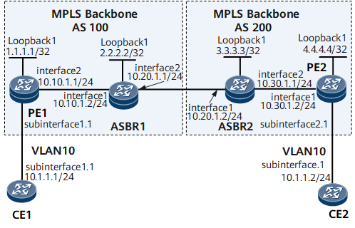
Networking Requirements
On the network shown in Figure 1, CE1 and CE2 access the backbone network through PE1 in AS100 and PE2 in AS200, respectively.
Inter-AS BGP VPLS Option C needs to be deployed for CE1 and CE2 to communicate.
Configuration Roadmap
The configuration roadmap is as follows:
Configure an IGP for each AS on the backbone network to ensure IP connectivity within the same AS.
Configure basic MPLS functions on the backbone network and establish a dynamic LSP between the PE and ASBR in the same AS. (ASBR interfaces also need to have basic MPLS functions configured.)
Establish an IBGP peer relationship between the PE and ASBR in the same AS.
Specify EBGP peers, configure routing policies, and enable label-based routing on ASBRs. Establish an MP-EBGP peer relationship between PE1 and PE2.
Configure VSIs on PEs and bind AC interfaces to these VSIs.
Data Preparation
To complete the configuration, you need the following data:
LSR IDs of the PEs and ASBRs
Name, RD, and VPN targets for each VSI
Names of the AC interfaces to be bound to VSIs
Routing policies used by ASBRs
Procedure
- Configure interface IP addresses.
# Configure CE1.
<HUAWEI> system-view
[~HUAWEI] sysname CE1
[*HUAWEI] commit
[~CE1] interface gigabitethernet 0/1/0
[*CE1-GigabitEthernet0/1/0] undo shutdown
[*CE1-GigabitEthernet0/1/0] quit
[*CE1] interface gigabitethernet 0/1/0.1
[*CE1-GigabitEthernet0/1/0.1] ip address 10.1.1.1 24
[*CE1-GigabitEthernet0/1/0.1] quit
[*CE1] commit
# Configure PE1.
<HUAWEI> system-view
[~HUAWEI] sysname PE1
[*HUAWEI] commit
[~PE1] interface loopback1
[*PE1-Loopback1] ip address 1.1.1.1 32
[*PE1-Loopback1] quit
[*PE1] interface gigabitethernet 0/1/0
[*PE1-GigabitEthernet0/1/0] undo shutdown
[*PE1-GigabitEthernet0/1/0] quit
[*PE1] interface gigabitethernet 0/1/0.1
[*PE1-GigabitEthernet0/1/0.1] quit
[*PE1] interface gigabitethernet 0/1/8
[*PE1-GigabitEthernet0/1/8] undo shutdown
[*PE1-GigabitEthernet0/1/8] ip address 10.10.1.1 24
[*PE1-GigabitEthernet0/1/8] quit
[*PE1] commit
# Configure ASBR1.
<HUAWEI> system-view
[~HUAWEI] sysname ASBR1
[*HUAWEI] commit
[~ASBR1] interface loopback1
[*ASBR1-Loopback1] ip address 2.2.2.2 32
[*ASBR1-Loopback1] quit
[*ASBR1] interface gigabitethernet 0/1/0
[*ASBR1-GigabitEthernet0/1/0] undo shutdown
[*ASBR1-GigabitEthernet0/1/0] ip address 10.10.1.2 24
[*ASBR1-GigabitEthernet0/1/0] quit
[*ASBR1] interface gigabitethernet 0/1/8
[*ASBR1-GigabitEthernet0/1/8] undo shutdown
[*ASBR1-GigabitEthernet0/1/8] ip address 10.20.1.1 24
[*ASBR1-GigabitEthernet0/1/8] quit
[*ASBR1] commit
# Configure ASBR2.
<HUAWEI> system-view
[~HUAWEI] sysname ASBR2
[*HUAWEI] commit
[~ASBR2] interface loopback1
[*ASBR2-Loopback1] ip address 3.3.3.3 32
[*ASBR2-Loopback1] quit
[*ASBR2] interface gigabitethernet 0/1/0
[*ASBR2-GigabitEthernet0/1/0] undo shutdown
[*ASBR2-GigabitEthernet0/1/0] ip address 10.20.1.2 24
[*ASBR2-GigabitEthernet0/1/0] quit
[*ASBR2] interface gigabitethernet 0/1/8
[*ASBR2-GigabitEthernet0/1/8] undo shutdown
[*ASBR2-GigabitEthernet0/1/8] ip address 10.30.1.1 24
[*ASBR2-GigabitEthernet0/1/8] quit
[*ASBR2] commit
# Configure PE2.
<HUAWEI> system-view
[~HUAWEI] sysname PE2
[*HUAWEI] commit
[~PE2] interface loopback1
[*PE2-Loopback1] ip address 4.4.4.4 32
[*PE2-Loopback1] quit
[*PE2] interface gigabitethernet 0/1/0
[*PE2-GigabitEthernet0/1/0] undo shutdown
[*PE2-GigabitEthernet0/1/0] ip address 10.30.1.1 24
[*PE2-GigabitEthernet0/1/0] quit
[*PE2] interface gigabitethernet 0/1/8
[*PE2-GigabitEthernet0/1/8] undo shutdown
[*PE2-GigabitEthernet0/1/8] quit
[*PE2] interface gigabitethernet 0/1/8.1
[*PE2-GigabitEthernet0/1/8.1] quit
[*PE2] commit
# Configure CE2.
<HUAWEI> system-view
[~HUAWEI] sysname CE2
[*HUAWEI] commit
[~CE2] interface gigabitethernet 0/1/0
[*CE2-GigabitEthernet0/1/0] undo shutdown
[*CE2-GigabitEthernet0/1/0] quit
[*CE2] interface gigabitethernet 0/1/0.1
[*CE2-GigabitEthernet0/1/0.1] ip address 10.1.1.2 24
[*CE2-GigabitEthernet0/1/0.1] quit
[*CE2] commit
- Configure an IGP on the backbone network.
# Configure PE1.
[~PE1] ospf 1
[*PE1-ospf-1] area 0.0.0.0
[*PE1-ospf-1-area-0.0.0.0] network 1.1.1.1 0.0.0.0
[*PE1-ospf-1-area-0.0.0.0] network 10.10.1.0 0.0.0.255
[*PE1-ospf-1-area-0.0.0.0] quit
[*PE1-ospf-1] quit
[*PE1] commit
# Configure ASBR1.
[~ASBR1] ospf 1
[*ASBR1-ospf-1] area 0.0.0.0
[*ASBR1-ospf-1-area-0.0.0.0] network 2.2.2.2 0.0.0.0
[*ASBR1-ospf-1-area-0.0.0.0] network 10.10.1.0 0.0.0.255
[*ASBR1-ospf-1-area-0.0.0.0] quit
[*ASBR1-ospf-1] quit
[*ASBR1] commit
# Configure ASBR2.
[*ASBR2] ospf 1
[*ASBR2-ospf-1] area 0.0.0.0
[*ASBR2-ospf-1-area-0.0.0.0] network 3.3.3.3 0.0.0.0
[*ASBR2-ospf-1-area-0.0.0.0] network 10.30.1.0 0.0.0.255
[*ASBR2-ospf-1-area-0.0.0.0] quit
[*ASBR2-ospf-1] quit
[*ASBR2] commit
# Configure PE2.
[~PE2] ospf 1
[*PE2-ospf-1] area 0.0.0.0
[*PE2-ospf-1-area-0.0.0.0] network 4.4.4.4 0.0.0.0
[*PE2-ospf-1-area-0.0.0.0] network 10.30.1.0 0.0.0.255
[*PE2-ospf-1-area-0.0.0.0] quit
[*PE2-ospf-1] quit
[*PE2] commit
- Configure basic MPLS functions and establish LSPs.
# Configure PE1.
[~PE1] mpls lsr-id 1.1.1.1
[*PE1] mpls
[*PE1-mpls] quit
[*PE1] mpls ldp
[*PE1-mpls-ldp] quit
[*PE1] inerface gigabitethernet 0/1/8
[*PE1-GigabitEthernet0/1/8] mpls
[*PE1-GigabitEthernet0/1/8] mpls ldp
[*PE1-GigabitEthernet0/1/8] quit
[*PE1] commit
# Configure ASBR1.
[*ASBR1] mpls lsr-id 2.2.2.2
[*ASBR1] mpls
[*ASBR1-mpls] quit
[*ASBR1] mpls ldp
[*ASBR1-mpls-ldp] quit
[*ASBR1] inerface gigabitethernet 0/1/0
[*ASBR1-GigabitEthernet0/1/0] mpls
[*ASBR1-GigabitEthernet0/1/0] mpls ldp
[*ASBR1-GigabitEthernet0/1/0] quit
[*ASBR1] commit
# Configure ASBR2.
[~ASBR2] mpls lsr-id 3.3.3.3
[*ASBR2] mpls
[*ASBR2-mpls] quit
[*ASBR2] mpls ldp
[*ASBR2-mpls-ldp] quit
[*ASBR2] inerface gigabitethernet 0/1/8
[*ASBR2-GigabitEthernet0/1/8] mpls
[*ASBR2-GigabitEthernet0/1/8] mpls ldp
[*ASBR2-GigabitEthernet0/1/8] quit
[*ASBR2] commit
# Configure PE2.
[~PE2] mpls lsr-id 4.4.4.4
[*PE2] mpls
[*PE2-mpls] quit
[*PE2] mpls ldp
[*PE2-mpls-ldp] quit
[*PE2] inerface gigabitethernet 0/1/0
[*PE2-GigabitEthernet0/1/0] mpls
[*PE2-GigabitEthernet0/1/0] mpls ldp
[*PE2-GigabitEthernet0/1/0] quit
[*PE2] commit
- Enable inter-AS MPLS on ASBRs.
# Configure ASBR1.
[~ASBR1] inerface gigabitethernet 0/1/8
[*ASBR1-GigabitEthernet0/1/8] mpls
[*ASBR1-GigabitEthernet0/1/8-mpls] quit
[*ASBR1] commit
# Configure ASBR2.
[~ASBR2] inerface gigabitethernet 0/1/0
[*ASBR2-GigabitEthernet0/1/0] mpls
[*ASBR2-GigabitEthernet0/1/0-mpls] quit
[*ASBR2] commit
- Establish an IBGP peer relationship between the PE and ASBR in the same AS, set up an EBGP peer relationship between ASBRs, and configure routing policies on ASBRs. These routing policies ensure that an ASBR reallocates MPLS labels to labeled IPv4 routes to be advertised to local PEs and allocates MPLS labels to routes to be advertised to the peer ASBR.
# Configure PE1.
[~PE1] bgp 100
[*PE1-bgp] peer 2.2.2.2 as-number 100
[*PE1-bgp] peer 2.2.2.2 label-route-capability
[*PE1-bgp] peer 2.2.2.2 connect-interface LoopBack 1
[*PE1-bgp] quit
[*PE1] commit
# Configure ASBR1.
[*ASBR1] route-policy policy1 permit node 1
[*ASBR1-route-policy] if-match mpls-label
[*ASBR1-route-policy] apply mpls-label
[*ASBR1-route-policy] quit
[*ASBR1] route-policy policy2 permit node 1
[*ASBR1-route-policy] apply mpls-label
[*ASBR1-route-policy] quit
[*ASBR1] bgp 100
[*ASBR1-bgp] network 1.1.1.1 255.255.255.255
[*ASBR1-bgp] peer 1.1.1.1 as-number 100
[*ASBR1-bgp] peer 1.1.1.1 route-policy policy1 export
[*ASBR1-bgp] peer 1.1.1.1 label-route-capability
[*ASBR1-bgp] peer 1.1.1.1 connect-interface loopback 1
[*ASBR1-bgp] peer 10.20.1.2 as-number 200
[*ASBR1-bgp] peer 10.20.1.2 route-policy policy2 export
[*ASBR1-bgp] peer 10.20.1.2 label-route-capability check-tunnel-reachable
[*ASBR1-bgp] peer 10.20.1.2 connect-interface gigabitethernet 0/1/8
[*ASBR1-bgp]quit
[*ASBR1]commit
# Configure ASBR2.
[*ASBR2] route-policy policy1 permit node 1
[*ASBR2-route-policy] if-match mpls-label
[*ASBR2-route-policy] apply mpls-label
[*ASBR2-route-policy] quit
[*ASBR2] route-policy policy2 permit node 1
[*ASBR2-route-policy] apply mpls-label
[*ASBR2-route-policy] quit
[*ASBR2] bgp 200
[*ASBR2-bgp] network 4.4.4.4 255.255.255.255
[*ASBR2-bgp] peer 4.4.4.4 as-number 200
[*ASBR2-bgp] peer 4.4.4.4 route-policy policy1 export
[*ASBR2-bgp] peer 4.4.4.4 label-route-capability
[*ASBR2-bgp] peer 4.4.4.4 connect-interface loopback 1
[*ASBR2-bgp] peer 10.20.1.1 as-number 100
[*ASBR2-bgp] peer 10.20.1.1 route-policy policy2 export
[*ASBR2-bgp] peer 10.20.1.1 label-route-capability check-tunnel-reachable
[*ASBR2-bgp] peer 10.20.1.1 connect-interface gigabitethernet 0/1/0
[*ASBR2-bgp] quit
[*ASBR2] commit
# Configure PE2.
[~PE2] bgp 200
[*PE2-bgp] peer 3.3.3.3 as-number 200
[*PE2-bgp] peer 3.3.3.3 label-route-capability
[*PE2-bgp] peer 3.3.3.3 connect-interface loopback 1
[*PE2-bgp] quit
[*PE2] commit
After completing the configurations, run the display bgp peer command on each ASBR. The command output shows that the status of the IBGP session between the PE and ASBR in the same AS is Established, and the status of the EBGP session between ASBRs is also Established. The following example uses the command output on ASBR1.
[~ASBR1] display bgp peer
 BGP local router ID : 2.2.2.2
 Local AS number : 100
 Total number of peers : 2                 Peers in established state : 2
 Peer            V    AS  MsgRcvd  MsgSent  OutQ  Up/Down       State  PrefRcv
 1.1.1.1         4   100      111      128     0 00:34:24 Established       0
10.20.1.2        4   200       75       89     0 00:38:40 Established       1
Run the display tunnel-info all command on each ASBR. The command output shows that a tunnel with the type being mpls local ifnet has been established. The following example uses the command output on ASBR1.
[~ASBR1] display tunnel-info all Tunnel ID Type Destination Status ----------------------------------------------------------------------------- 0x0000000001004c4b42 ldp 1.1.1.1 UP 0x000000000c00030000 mpls local ifnet 10.20.1.2 UP - Establish an MP-EBGP peer relationship between PE1 and PE2.

The capability to exchange route information with BGP peers must be configured in the L2VPN-AD address family view for PEs to exchange VPLS block information.
# Configure PE1.
[~PE1] bgp 100
[*PE1-bgp] peer 4.4.4.4 as-number 200
[*PE1-bgp] peer 4.4.4.4 ebgp-max-hop 255
[*PE1-bgp] peer 4.4.4.4 connect-interface loopback 1
[*PE1-bgp] l2vpn-ad-family
[*PE1-bgp-af-l2vpn-ad] peer 4.4.4.4 enable
[*PE1-bgp-af-l2vpn-ad] peer 4.4.4.4 signaling vpls
[*PE1-bgp-af-l2vpn-ad] quit
[*PE1-bgp] quit
[*PE1] commit
# Configure PE2.
[~PE2] bgp 200
[*PE2-bgp] peer 1.1.1.1 as-number 100
[*PE2-bgp] peer 1.1.1.1 ebgp-max-hop 255
[*PE2-bgp] peer 1.1.1.1 connect-interface loopback 1
[*PE2-bgp] l2vpn-ad-family
[*PE2-bgp-af-l2vpn-ad] peer 1.1.1.1 enable
[*PE2-bgp-af-l2vpn-ad] peer 1.1.1.1 signaling vpls
[*PE2-bgp-af-l2vpn-ad] quit
[*PE2-bgp] quit
[*PE2] commit
After completing the configurations, run the display bgp l2vpn-ad peer command on PE1 or PE2. The command output shows that the status of the MP-EBGP peer relationship between PE1 and PE2 is Established. The following example uses the command output on PE1.
[~PE1] display bgp l2vpn-ad peer
 BGP local router ID : 1.1.1.1
 Local AS number : 100
 Total number of peers : 1                 Peers in established state : 1
  Peer            V    AS  MsgRcvd  MsgSent  OutQ  Up/Down       State       PrefRcv
  4.4.4.4         4   200       74       66     0 00: 46:06      Established       1
Run the display tunnel-info all command on PE1 or PE2. The command output shows that an inter-AS LSP has been established between PE1 and PE2. The following example uses the command output on PE1.
[~PE1] display tunnel-info all Tunnel ID Type Destination Status ----------------------------------------------------------------------------- 0x0000000001004c4b42 ldp 2.2.2.2 UP 0x000000000201040000 bgp 4.4.4.4 UP - Configure VSIs on PEs and bind AC interfaces to these VSIs.
# Configure PE1.
[~PE1] mpls l2vpn
[*PE1-l2vpn] quit
[*PE1] vsi v1 auto
[*PE1-vsi-v1] pwsignal bgp
[*PE1-vsi-v1-bgp] route-distinguisher 100:1
[*PE1-vsi-v1-bgp] vpn-target 1:1 import-extcommunity
[*PE1-vsi-v1-bgp] vpn-target 1:1 export-extcommunity
[*PE1-vsi-v1-bgp] site 1 range 5 default-offset 0
[*PE1-vsi-v1-bgp] quit
[*PE1-vsi-v1] quit
[*PE1] interface gigabitethernet0/1/0.1
[*PE1-GigabitEthernet0/1/0.1] shutdown
[*PE1-GigabitEthernet0/1/0.1] vlan-type dot1q 10
[*PE1-GigabitEthernet0/1/0.1] l2 binding vsi v1
[*PE1-GigabitEthernet0/1/0.1] undo shutdown
[*PE1-GigabitEthernet0/1/0.1] quit
[*PE1] commit
# Configure PE2.
[~PE2] mpls l2vpn
[*PE2-l2vpn] quit
[*PE2] vsi v1 auto
[*PE2-vsi-v1] pwsignal bgp
[*PE2-vsi-v1-bgp] route-distinguisher 200:1
[*PE2-vsi-v1-bgp] vpn-target 1:1 import-extcommunity
[*PE2-vsi-v1-bgp] vpn-target 1:1 export-extcommunity
[*PE2-vsi-v1-bgp] site 2 range 5 default-offset 0
[*PE2-vsi-v1-bgp] quit
[*PE2-vsi-v1] quit
[*PE2] interface gigabitethernet0/1/8.1
[*PE2-GigabitEthernet0/1/8.1] shutdown
[*PE2-GigabitEthernet0/1/8.1] vlan-type dot1q 10
[*PE2-GigabitEthernet0/1/8.1] l2 binding vsi v1
[*PE2-GigabitEthernet0/1/8.1] undo shutdown
[*PE2-GigabitEthernet0/1/8.1] quit
[*PE2] commit
# Configure CE1.
[~CE1] interface gigabitethernet0/1/0.1
[*CE1-GigabitEthernet0/1/0.1] shutdown
[*CE1-GigabitEthernet0/1/0.1] vlan-type dot1q 10
[*CE1-GigabitEthernet0/1/0.1] ip address 10.1.1.1 24
[*CE1-GigabitEthernet0/1/0.1] undo shutdown
[*CE1-GigabitEthernet0/1/0.1] quit
[*CE1] commit
# Configure CE2.
[~CE2] interface gigabitethernet0/1/0.1
[*CE2-GigabitEthernet0/1/0.1] shutdown
[*CE2-GigabitEthernet0/1/0.1] vlan-type dot1q 10
[*CE2-GigabitEthernet0/1/0.1] ip address 10.1.1.2 24
[*CE2-GigabitEthernet0/1/0.1] undo shutdown
[*CE2-GigabitEthernet0/1/0.1] quit
[*CE2] commit
- Verify the configuration.
After completing the configurations, run the display vsi name v1 verbose command on PE1 or PE2. The command output shows that VSI State and PW State are both up. The PW is carried over the previously established inter-AS LSP. The following example uses the command output on PE1.
[~PE1] display vsi name v1 verbose
 ***VSI Name               : v1
    Administrator VSI      : no
    Isolate Spoken         : disable
    VSI Index              : 0
    PW Signaling           : bgp
    Member Discovery Style : auto
    PW MAC Learn Style     : unqualify
    Encapsulation Type     : vlan
    MTU                    : 1500
    Diffserv Mode          : uniform
    Service Class          : --
    Color                  : --
    DomainId               : 255
    Domain Name            :
    Ignore AcState         : disable
    Multicast Fast Swicth  : disable
    Create Time            : 0 days, 0 hours, 27 minutes, 17 seconds
    VSI State              : up
    Resource Status        : Valid

    BGP RD                 : 100:1
    SiteID/Range/Offset    : 1/5/0
    Import vpn target      : 1:1
    Export vpn target      : 1:1

    Remote Label Block     : 25600/5/0
    Local Label Block      : 25600/5/0
    Interface Name         : GigabitEthernet0/1/0.1
    State                  : up
    Last Up Time           : 2014/05/17 10:29:49
    Total Up Time          : 0 days, 0 hours, 26 minutes, 27 seconds

   **PW Information:

   *Peer Ip Address        : 4.4.4.4
    PW State               : up
    Local VC Label         : 25602
    Remote VC Label        : 25601
    PW Type                : label
    Tunnel ID              : 0x6002024
    Broadcast Tunnel ID    : 0x6002024
    Ckey                   : 0x6
    Nkey                   : 0x5
    Main PW Token          : 0x6002024
    Slave PW Token         : 0x0
    Tnl Type               : BGP
    OutInterface           : 1POS0/1/8
    Stp Enable             : 0
    Mac Flapping           : 0
    PW Last Up Time        : 2014/05/17 10:31:05
    PW Total Up Time       : 0 days, 0 hours, 25 minutes, 32 seconds
Run the display vpls connection bgp verbose command on PE1. The command output shows that VC State is up.
[~PE1] display vpls connection bgp verbose
VSI Name: v1                               Signaling: bgp
  **Remote Site ID     : 2
    VC State           : up
    RD                 : 200:1
    Encapsulation      : bgp vpls
    MTU                : 1500
    Peer Ip Address    : 4.4.4.4
    PW Type            : label
    Local VC Label     : 25602
    Remote VC Label    : 25601
    Tunnel Policy      : --
    Tunnel ID          : 0x2002001
    Remote Label Block : 25600/5/0
    Export vpn target  : 1:1
CE1 and CE2 can ping each other. The following example uses the command output on CE1.
[~CE1] ping 10.1.1.2
  PING 10.1.1.2: 56  data bytes, press CTRL_C to break
    Reply from 10.1.1.2: bytes=56 Sequence=1 ttl=255 time=90 ms
    Reply from 10.1.1.2: bytes=56 Sequence=2 ttl=255 time=77 ms
    Reply from 10.1.1.2: bytes=56 Sequence=3 ttl=255 time=34 ms
    Reply from 10.1.1.2: bytes=56 Sequence=4 ttl=255 time=46 ms
    Reply from 10.1.1.2: bytes=56 Sequence=5 ttl=255 time=94 ms
  --- 10.1.1.2 ping statistics ---
    5 packet(s) transmitted
    5 packet(s) received
    0.00% packet loss
    round-trip min/avg/max = 34/68/94 ms
Configuration Files
CE1 configuration file
#
sysname CE1
#
interface GigabitEthernet0/1/0
 undo shutdown
#
interface GigabitEthernet0/1/0.1
 undo shutdown
 vlan-type dot1q 10
 ip address 10.1.1.1 255.255.255.0
#
return
PE1 configuration file
#
sysname PE1
#
mpls lsr-id 1.1.1.1
#
mpls
#
mpls l2vpn
#
vsi v1 auto
 pwsignal bgp
  route-distinguisher 100:1
  vpn-target 1:1 import-extcommunity
  vpn-target 1:1 export-extcommunity
  site 1 range 5 default-offset 0
#
mpls ldp
#
interface GigabitEthernet0/1/0
 undo shutdown
#
interface GigabitEthernet0/1/0.1
 undo shutdown
 vlan-type dot1q 10
 l2 binding vsi v1
#
interface GigabitEthernet0/1/8
 ip address 10.10.1.1 255.255.255.0
 mpls
 mpls ldp
#
interface LoopBack1
 ip address 1.1.1.1 255.255.255.255
#
bgp 100
 peer 2.2.2.2 as-number 100
 peer 2.2.2.2 connect-interface LoopBack1
 peer 4.4.4.4 as-number 200
 peer 4.4.4.4 ebgp-max-hop 255
 peer 4.4.4.4 connect-interface LoopBack1
#
ipv4-family unicast
 undo synchronization
 peer 2.2.2.2 enable
 peer 2.2.2.2 label-route-capability
 peer 4.4.4.4 enable
#
l2vpn-ad-family
 policy vpn-target
 peer 4.4.4.4 enable
 peer 4.4.4.4 signaling vpls
#
ospf 1
 area 0.0.0.0
  network 1.1.1.1 0.0.0.0
  network 10.10.1.0 0.0.0.255
#
return
ASBR1 configuration file
#
sysname ASBR1
#
mpls lsr-id 2.2.2.2
#
mpls
#
mpls l2vpn
#
mpls ldp
#
interface GigabitEthernet0/1/0
 undo shutdown
 ip address 10.10.1.2 255.255.255.0
 mpls
 mpls ldp
#
interface GigabitEthernet0/1/8
 undo shutdown
 ip address 10.20.1.1 255.255.255.0
 mpls
#
interface LoopBack1
 ip address 2.2.2.2 255.255.255.255
#
bgp 100
 peer 1.1.1.1 as-number 100
 peer 1.1.1.1 connect-interface LoopBack1
 peer 10.20.1.2 as-number 200
 peer 10.20.1.2 connect-interface GigabitEthernet0/1/8

#
ipv4-family unicast
 undo synchronization
 network 1.1.1.1 255.255.255.255
 peer 1.1.1.1 enable
 peer 1.1.1.1 route-policy policy1 export
 peer 1.1.1.1 label-route-capability
 peer 10.20.1.2 enable
 peer 10.20.1.2 route-policy policy2 export
 peer 10.20.1.2 label-route-capability check-tunnel-reachable
#
route-policy policy1 permit node 1
 if-match mpls-label
 apply mpls-label
route-policy policy2 permit node 1
 apply mpls-label
#
ospf 1
 area 0.0.0.0
  network 2.2.2.2 0.0.0.0
  network 10.10.1.0 0.0.0.255
#
return
ASBR2 configuration file
#
sysname ASBR2
#
mpls lsr-id 3.3.3.3
#
mpls
#
mpls l2vpn
#
mpls ldp
#
interface GigabitEthernet0/1/0
 undo shutdown
 ip address 10.20.1.2 255.255.255.252
 mpls
#
interface GigabitEthernet0/1/8
 undo shutdown
 ip address 10.30.1.1 255.255.255.0
 mpls
 mpls ldp
#
interface LoopBack1
 ip address 3.3.3.3 255.255.255.255
#
bgp 200
 peer 4.4.4.4 as-number 200
 peer 4.4.4.4 connect-interface LoopBack1
 peer 10.20.1.1 as-number 100
 peer 10.20.1.1 connect-interface GigabitEthernet0/1/0
#
ipv4-family unicast
 undo synchronization
 network 4.4.4.4 255.255.255.255
 peer 4.4.4.4 enable
 peer 4.4.4.4 route-policy policy1 export
 peer 4.4.4.4 label-route-capability
 peer 10.20.1.1 enable
 peer 10.20.1.1 route-policy policy2 export
 peer 10.20.1.1 label-route-capability check-tunnel-reachable
#
route-policy policy1 permit node 1
 if-match mpls-label
 apply mpls-label
route-policy policy2 permit node 1
 apply mpls-label
#
ospf 1
 area 0.0.0.0
  network 3.3.3.3 0.0.0.0
  network 10.30.1.0 0.0.0.255
#
return
PE2 configuration file
#
sysname PE2
#
mpls lsr-id 4.4.4.4
#
mpls
#
mpls l2vpn
#
vsi v1 auto
 pwsignal bgp
  route-distinguisher 200:1
  vpn-target 1:1 import-extcommunity
  vpn-target 1:1 export-extcommunity
  site 2 range 5 default-offset 0
#
mpls ldp
#
interface GigabitEthernet0/1/8
 undo shutdown
#
interface GigabitEthernet0/1/8.1
 undo shutdown
 vlan-type dot1q 10
 l2 binding vsi v1
#
interface GigabitEthernet0/1/0
 undo shutdown
 ip address 10.30.1.2 255.255.255.0
 mpls
 isis enable 1
 mpls ldp
#
interface LoopBack1
 ip address 4.4.4.4 255.255.255.255
#
bgp 200
 peer 1.1.1.1 as-number 100
 peer 1.1.1.1 ebgp-max-hop 255
 peer 1.1.1.1 connect-interface LoopBack1
 peer 3.3.3.3 as-number 200
 peer 3.3.3.3 connect-interface LoopBack1
#
ipv4-family unicast
 undo synchronization
 peer 1.1.1.1 enable
 peer 3.3.3.3 enable
 peer 3.3.3.3 label-route-capability
#
l2vpn-ad-family
 policy vpn-target
 peer 1.1.1.1 enable
 peer 1.1.1.1 signaling vpls
#
ospf 1
 area 0.0.0.0
  network 4.4.4.4 0.0.0.0
  network 10.30.1.0 0.0.0.255
#
return
CE2 configuration file
#
sysname CE2
#
interface GigabitEthernet0/1/0
 undo shutdown
#
interface GigabitEthernet0/1/0.1
 undo shutdown
 vlan-type dot1q 10
 ip address 10.1.1.2 255.255.255.0
#
return