Example for Configuring a Dynamic VPWS SS-PW Using an LSP
This section provides an example for configuring a dynamic VPWS SS-PW using an LSP.
Networking Requirements
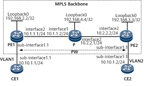
On the network shown in Figure 1, CE1 and CE2 connect to PE1 and PE2, respectively; PE1 and PE2 are connected over an MPLS backbone network.
An LSP is needed to set up a dynamic VPWS SS-PW between PE1 and PE2.

Configuration Roadmap
The configuration roadmap is as follows:
Enable an IGP on the MPLS backbone network for devices on the backbone network to communicate.
Enable basic MPLS functions on the MPLS backbone network and establish an LSP. Then, establish a remote MPLS LDP peer relationship between PEs at the two ends of the PW to be created.
Create a dynamic VPWS SS-PW between PEs.
Data Preparation
To complete the configuration, you need the following data:
L2VC IDs at the two ends of the PW (must be the same)
MPLS LSR IDs of the PEs and P
IP address of the remote peer of each PE
Procedure
- Assign IP addresses to CE interfaces that connect to PEs.
# Configure CE1.
<HUAWEI> system-view
[~HUAWEI] sysname CE1
[*HUAWEI] commit
[~CE1] interface gigabitethernet 0/1/0
[*CE1-GigabitEthernet0/1/0] undo shutdown
[*CE1-GigabitEthernet0/1/0] quit
[*CE1] interface gigabitethernet 0/1/0.1
[*CE1-GigabitEthernet0/1/0.1] vlan-type dot1q 1
[*CE1-GigabitEthernet0/1/0.1] ip address 10.10.1.1 24
[*CE1-GigabitEthernet0/1/0.1] undo shutdown
[*CE1-GigabitEthernet0/1/0.1] commit
[~CE1-GigabitEthernet0/1/0.1] quit
# Configure CE2.
<HUAWEI> system-view
[~HUAWEI] sysname CE2
[*HUAWEI] commit
[~CE2] interface gigabitethernet 0/1/0
[*CE2-GigabitEthernet0/1/0] undo shutdown
[*CE2-GigabitEthernet0/1/0] quit
[*CE2] interface gigabitethernet 0/1/0.1
[*CE2-GigabitEthernet0/1/0.1] vlan-type dot1q 2
[*CE2-GigabitEthernet0/1/0.1] ip address 10.10.1.2 24
[*CE2-GigabitEthernet0/1/0.1] undo shutdown
[*CE2-GigabitEthernet0/1/0.1] commit
[~CE2-GigabitEthernet0/1/0.1] quit
- Configure an IGP on the MPLS backbone network.
Configure an IGP (OSPF in this example) on the MPLS backbone network. For details about how to configure OSPF, see "OSPF Configuration" in NetEngine 8000 F Configuration Guide - IP Routing.
The configuration details are not provided here.
- Configure basic MPLS functions and establish an LSP and a remote LDP session.
For details about how to configure MPLS, see NetEngine 8000 F Configuration Guide - MPLS.
After completing the configurations, run the display mpls ldp session command. The command output shows that an LDP session has been established between the PEs and between each PE and the P. The status of these LDP sessions is Operational.
The following example uses the command output on PE1.
<PE1> display mpls ldp session LDP Session(s) in Public Network Codes: LAM(Label Advertisement Mode), SsnAge Unit(DDDD:HH:MM) An asterisk (*) before a session means the session is being deleted. -------------------------------------------------------------------------- PeerID Status LAM SsnRole SsnAge KASent/Rcv -------------------------------------------------------------------------- 192.168.3.3:0 Operational DU Passive 000:00:00 4/5 192.168.4.4:0 Operational DU Passive 000:00:02 10/10 -------------------------------------------------------------------------- TOTAL: 2 Session(s) Found. - Create a dynamic VPWS SS-PW.
Enable MPLS L2VPN on PE1 and PE2 and create a dynamic VPWS SS-PW between the two PEs.
# Configure PE1.
[~PE1] mpls l2vpn
[*PE1-l2vpn] quit
[*PE1] mpls ldp remote-peer 192.168.3.3
[*PE1-mpls-ldp-remote-192.168.3.3] remote-ip 192.168.3.3
[*PE1-mpls-ldp-remote-192.168.3.3] quit
[*PE1] interface gigabitethernet 0/1/0
[*PE1-GigabitEthernet0/1/0] undo shutdown
[*PE1-GigabitEthernet0/1/0] quit
[*PE1] interface gigabitethernet 0/1/0.1
[*PE1-GigabitEthernet0/1/0.1] vlan-type dot1q 1
[*PE1-GigabitEthernet0/1/0.1] mpls l2vc 192.168.3.3 100
[*PE1-GigabitEthernet0/1/0.1] undo shutdown
[*PE1-GigabitEthernet0/1/0.1] commit
[~PE1-GigabitEthernet0/1/0.1] quit
# Configure PE2.
[~PE2] mpls l2vpn
[*PE2-l2vpn] quit
[*PE2] mpls ldp remote-peer 192.168.2.2
[*PE2-mpls-ldp-remote-192.168.2.2] remote-ip 192.168.2.2
[*PE1-mpls-ldp-remote-192.168.2.2] quit
[*PE2] interface gigabitethernet 0/1/0
[*PE2-GigabitEthernet0/1/0] undo shutdown
[*PE2-GigabitEthernet0/1/0] quit
[*PE2] interface gigabitethernet0/1/0.1
[*PE2-GigabitEthernet0/1/0.1] vlan-type dot1q 2
[*PE2-GigabitEthernet0/1/0.1] mpls l2vc 192.168.2.2 100
[*PE2-GigabitEthernet0/1/0.1] undo shutdown
[*PE2-GigabitEthernet0/1/0.1] commit
[~PE2-GigabitEthernet0/1/0.1] quit
- Verify the configuration.
View VPWS SS-PW information on PEs. The command output shows that an SS-PW has been established and its VC status is Up.
The following example uses the command output on PE1.
<PE1> display mpls l2vc interface gigabitethernet 0/1/0.1
*client interface       : GigabitEthernet0/1/0.1 is up
 Administrator PW       : no
 session state          : up
 AC status              : up
 VC state               : up
 Label state            : 0
 Token state            : 0
 VC ID                  : 100
 VC type                : VLAN
 destination            : 192.168.3.3
 local group ID         : 0         remote group ID      : 0
 local VC label         : 18        remote VC label      : 18
 local AC OAM State     : up
 local PSN OAM State    : up
 local forwarding state : forwarding
 local status code      : 0x0 (forwarding)
 remote AC OAM State    : up
 remote PSN OAM state   : up
 remote forwarding state: forwarding
 remote status code     : 0x0 (forwarding)
 ignore standby state   : no
 BFD for PW             : unavailable
 VCCV State             : --
 manual fault           : not set
 active state           : active
 forwarding entry       : exist
 OAM Protocol           : --
 OAM Status             : --
 OAM Fault Type         : --

 PW APS ID              : --
 PW APS Status          : --
 TTL Value              : 1
 link state             : up
 local VC MTU           : 1500      remote VC MTU        : 1500
 local VCCV             : alert ttl lsp-ping bfd
 remote VCCV            : alert ttl lsp-ping bfd
 local control word     : disable   remote control word  : disable
 tunnel policy name     : --
 PW template name       : --
 primary or secondary   : primary
 load balance type      : flow
 Access-port            : false
 Switchover Flag        : false
 VC tunnel info         : 1 tunnels
    NO.0 TNL type       : ldp, TNL ID : 0x0000000001004c4b43
 create time            : 0 days, 0 hours, 6 minutes, 29 seconds
 up time                : 0 days, 0 hours, 5 minutes, 21 seconds
 last change time       : 0 days, 0 hours, 5 minutes, 21 seconds
 VC last up time        : 2012/12/05 02:50:41
 VC total up time       : 0 days, 0 hours, 5 minutes, 21 seconds
 CKey                   : 1
 NKey                   : 1493172332
 PW redundancy mode     : frr
 AdminPw interface      : --
 AdminPw link state     : --
 Forward state          : send inactive, receive inactive
 Diffserv Mode          : uniform
 Service Class          : --
 Color                  : --
 DomainId               : --
 Domain Name            : --
CE1 and CE2 can ping each other.
The following example uses the command output on CE1.
<CE1> ping 10.10.1.2
  PING 10.10.1.2: 56  data bytes, press CTRL_C to break
    Reply from 10.10.1.2: bytes=56 Sequence=1 ttl=255 time=6 ms
    Reply from 10.10.1.2: bytes=56 Sequence=2 ttl=255 time=2 ms
    Reply from 10.10.1.2: bytes=56 Sequence=3 ttl=255 time=2 ms
    Reply from 10.10.1.2: bytes=56 Sequence=4 ttl=255 time=3 ms
    Reply from 10.10.1.2: bytes=56 Sequence=5 ttl=255 time=2 ms

  --- 10.10.1.2 ping statistics ---
    5 packet(s) transmitted
    5 packet(s) received
    0.00% packet loss
    round-trip min/avg/max = 2/3/6 ms
Configuration Files
CE1 configuration file
#
sysname CE1
#
interface GigabitEthernet0/1/0
 undo shutdown
#
interface GigabitEthernet0/1/0.1
 vlan-type dot1q 1
 ip address 10.10.1.1 255.255.255.0
#
return
PE1 configuration file
#
sysname PE1
#
mpls lsr-id 192.168.2.2
#
mpls
#
mpls l2vpn
#
mpls ldp
#
mpls ldp remote-peer 192.168.3.3
 remote-ip 192.168.3.3
#
interface GigabitEthernet0/1/0
 undo shutdown
#
interface GigabitEthernet0/1/0.1
 vlan-type dot1q 1
 mpls l2vc 192.168.3.3 100
#
interface GigabitEthernet0/1/8
 undo shutdown
 ip address 10.1.1.1 255.255.255.0
 mpls
 mpls ldp
#
interface LoopBack0
 ip address 192.168.2.2 255.255.255.255
#
ospf 1
area 0.0.0.0
  network 192.168.2.2 0.0.0.0
  network 10.1.1.0 0.0.0.255
#
return
P configuration file
#
sysname P
#
mpls lsr-id 192.168.4.4
#
mpls
#
mpls ldp
#
interface
GigabitEthernet0/1/0
 undo shutdown
 ip address 10.1.1.2 255.255.255.0
 mpls
 mpls ldp
#
interface GigabitEthernet0/1/8
 undo shutdown
 ip address 10.2.2.1 255.255.255.0
 mpls
 mpls ldp
#
interface LoopBack0
 ip address 192.168.4.4 255.255.255.255
#
ospf 1
 area 0.0.0.0
  network 192.168.4.4 0.0.0.0
  network 10.1.1.0 0.0.0.255
  network 10.2.2.0 0.0.0.255
#
return
PE2 configuration file
#
sysname PE2
#
mpls lsr-id 192.168.3.3
#
mpls
#
mpls l2vpn
#
mpls ldp
#
mpls ldp remote-peer 192.168.2.2
 remote-ip 192.168.2.2
#
interface GigabitEthernet0/1/0
 undo shutdown
#
interface GigabitEthernet 0/1/0.1
 vlan-type dot1q 2
 mpls l2vc 192.168.2.2 100
#
interface GigabitEthernet0/1/8
 undo shutdown
 ip address 10.2.2.2 255.255.255.0
 mpls
 mpls ldp
#
interface LoopBack0
 ip address 192.168.3.3 255.255.255.255
#
ospf 1
 area 0.0.0.0
  network 192.168.3.3 0.0.0.0
  network 10.2.2.0 0.0.0.255
#
return
CE2 configuration file
#
sysname CE2
#
interface GigabitEthernet0/1/0
 undo shutdown
#
interface GigabitEthernet0/1/0.1
 vlan-type dot1q 2
 ip address 10.10.1.2 255.255.255.0
#
return