Example for Configuring a Dynamic VPWS SS-PW Using a TE Tunnel
This section provides an example for configuring a dynamic VPWS SS-PW using a TE tunnel.
Networking Requirements
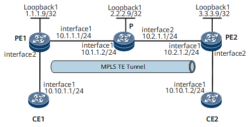
On the network shown in Figure 1, CE1 and CE2 belong to the same VPN and access the MPLS backbone network through PE1 and PE2, respectively. OSPF is used as an IGP on the MPLS backbone network.
A VPWS SS-PW is required. The dynamic signaling protocol RSVP-TE is used to establish an MPLS TE tunnel between PE1 and PE2 to transmit VPWS traffic at 2 Mbit/s. The maximum link bandwidth of the tunnel is 5 Mbit/s, and the maximum reservable bandwidth is 10 Mbit/s.
Configuration Roadmap
The configuration roadmap is as follows:
Enable an IGP on the MPLS backbone network for devices on the backbone network to communicate.
Enable basic MPLS functions on the MPLS backbone network, establish an MPLS TE tunnel, and configure a tunnel policy. For details about how to configure an MPLS TE tunnel, see "MPLS TE Configuration" in NetEngine 8000 FConfiguration Guide - MPLS.
Enable MPLS L2VPN on PEs and establish a dynamic VPWS SS-PW.
Data Preparation
To complete the configuration, you need the following data:
OSPF area enabled with TE
Tunnel policy name
Number of routes for load balancing (if load balancing is not required, the number of routes is 1)
Procedure
- Configure an IP address and OSPF on each interface of the MPLS backbone network.
For configuration details, see Configuration Files in this section.
- Configure MPLS, MPLS TE, MPLS RSVP-TE, and MPLS TE constraint shortest path first (CSPF).
On the nodes along the MPLS TE tunnel, configure MPLS, MPLS TE, and MPLS RSVP-TE both in the system view and the interface view. On the ingress of the tunnel, enable MPLS CSPF in the system view.
# Configure PE1.
[~PE1] mpls lsr-id 1.1.1.9
[*PE1] mpls
[*PE1-mpls] mpls te
[*PE1-mpls] mpls rsvp-te
[*PE1-mpls] mpls te cspf
[*PE1-mpls] quit
[*PE1] interface gigabitethernet 1/0/0
[*PE1-GigabitEthernet1/0/0] mpls
[*PE1-GigabitEthernet1/0/0] mpls te
[*PE1-GigabitEthernet1/0/0] mpls rsvp-te
[*PE1-GigabitEthernet1/0/0] commit
[~PE1-GigabitEthernet1/0/0] quit
# Configure the P.
[~P] mpls lsr-id 2.2.2.9
[*P] mpls
[*P-mpls] mpls te
[*P-mpls] mpls rsvp-te
[*P-mpls] quit
[*P] interface gigabitethernet0/1/0
[*P-GigabitEthernet0/1/0] mpls
[*P-GigabitEthernet0/1/0] mpls te
[*P-GigabitEthernet0/1/0] mpls rsvp-te
[*P-GigabitEthernet0/1/0] quit
[*P] interface gigabitethernet0/1/8
[*P-GigabitEthernet0/1/8] mpls
[*P-GigabitEthernet0/1/8] mpls te
[*P-GigabitEthernet0/1/8] mpls rsvp-te
[*P-GigabitEthernet0/1/8] commit
[~P-GigabitEthernet0/1/8] quit
# Configure PE2.
[~PE2] mpls lsr-id 3.3.3.9
[*PE2] mpls
[*PE2-mpls] mpls te
[*PE2-mpls] mpls rsvp-te
[*PE2-mpls] mpls te cspf
[*PE2-mpls] quit
[*PE2] interface gigabitethernet 0/1/0
[*PE2-GigabitEthernet0/1/0] mpls
[*PE2-GigabitEthernet0/1/0] mpls te
[*PE2-GigabitEthernet0/1/0] mpls rsvp-te
[*PE2-GigabitEthernet0/1/0] commit
[~PE2-GigabitEthernet0/1/0] quit
- Configure OSPF TE on the MPLS backbone network.
# Configure PE1.
[~PE1] ospf
[*PE1-ospf-1] opaque-capability enable
[*PE1-ospf-1] area 0.0.0.0
[*PE1-ospf-1-area-0.0.0.0] network 1.1.1.9 0.0.0.0
[*PE1-ospf-1-area-0.0.0.0] network 10.1.1.0 0.0.0.255
[*PE1-ospf-1-area-0.0.0.0] mpls-te enable
[*PE1-ospf-1-area-0.0.0.0] commit
# Configure the P.
[~P] ospf
[*P-ospf-1] opaque-capability enable
[*P-ospf-1] area 0.0.0.0
[*P-ospf-1-area-0.0.0.0] network 2.2.2.9 0.0.0.0
[*P-ospf-1-area-0.0.0.0] network 10.1.1.0 0.0.0.255
[*P-ospf-1-area-0.0.0.0] network 10.2.1.0 0.0.0.255
[*P-ospf-1-area-0.0.0.0] mpls-te enable
[*P-ospf-1-area-0.0.0.0] commit
# Configure PE2.
[~PE2] ospf
[*PE2-ospf-1] opaque-capability enable
[*PE2-ospf-1] area 0.0.0.0
[*PE2-ospf-1-area-0.0.0.0] network 3.3.3.9 0.0.0.0
[*PE2-ospf-1-area-0.0.0.0] network 10.2.1.0 0.0.0.255
[*PE2-ospf-1-area-0.0.0.0] mpls-te enable
[*PE2-ospf-1-area-0.0.0.0] commit
- Configure MPLS TE attributes for links.
Configure the maximum link bandwidth and maximum reservable link bandwidth for each interface along the tunnel.
# Configure PE1.
[~PE1] interface gigabitethernet 0/1/0
[*PE1-GigabitEthernet0/1/0] mpls te bandwidth max-reservable-bandwidth 10000
[*PE1-GigabitEthernet0/1/0] mpls te bandwidth bc0 5000
[*PE1-GigabitEthernet0/1/0] commit
[~PE1-GigabitEthernet0/1/0] quit
# Configure the P.
[~P] interface gigabitethernet0/1/0
[*P-GigabitEthernet0/1/0] mpls te bandwidth max-reservable-bandwidth 10000
[*P-GigabitEthernet0/1/0] mpls te bandwidth bc0 5000
[*P-GigabitEthernet0/1/0] quit
[*P] interface gigabitethernet0/1/8
[*P-GigabitEthernet0/1/8] mpls te bandwidth max-reservable-bandwidth 10000
[*P-GigabitEthernet0/1/8] mpls te bandwidth bc0 5000
[*P-GigabitEthernet0/1/8] commit
[~P-GigabitEthernet0/2/0] quit
# Configure PE2.
[~PE2] interface gigabitethernet
[*PE2-GigabitEthernet0/1/0] mpls te bandwidth max-reservable-bandwidth 10000
[*PE2-GigabitEthernet0/1/0] mpls te bandwidth bc0 5000
[*PE2-GigabitEthernet0/1/0] commit
[~PE2-GigabitEthernet0/1/0] quit
- Configure tunnel interfaces.
# Create tunnel interfaces on PEs, specify the tunnel protocol as MPLS TE and the signaling protocol as RSVP-TE, and specify the bandwidth.
# Configure PE1.
[~PE1] interface Tunnel 10
[*PE1-Tunnel10] ip address unnumbered interface loopback1
[*PE1-Tunnel10] tunnel-protocol mpls te
[*PE1-Tunnel10] mpls te signal-protocol rsvp-te
[*PE1-Tunnel10] destination 3.3.3.9
[*PE1-Tunnel10] mpls te tunnel-id 10
[*PE1-Tunnel10] mpls te bandwidth ct0 2000
[*PE1-Tunnel10] commit
# Configure PE2.
[~PE2] interface Tunnel 10
[*PE2-Tunnel10] ip address unnumbered interface loopback1
[*PE2-Tunnel10] tunnel-protocol mpls te
[*PE2-Tunnel10] mpls te signal-protocol rsvp-te
[*PE2-Tunnel10] destination 1.1.1.9
[*PE2-Tunnel10] mpls te tunnel-id 10
[*PE2-Tunnel10] mpls te bandwidth ct0 2000
[*PE2-Tunnel10] commit
After completing the configurations, run the display this interface command in the tunnel interface view. In the command output, Line protocol current state is UP, indicating that the MPLS TE tunnel has been established.
[~PE1-Tunnel10] display this interface Tunnel10 current state : UP (ifindex: 37) Line protocol current state : UP Last line protocol up time : 2020-07-13 01:29:54 Description: Route Port,The Maximum Transmit Unit is 1500, Current BW: 2Mbps Internet Address is unnumbered, using address of LoopBack1(1.1.1.9/32) Encapsulation is TUNNEL, loopback not set Tunnel destination 3.3.3.9 Tunnel up/down statistics 1 Tunnel ct0 bandwidth is 2000 Kbit/sec Tunnel protocol/transport MPLS/MPLS, ILM is available primary tunnel id is 0x8001, secondary tunnel id is 0x0 Current system time: 2020-07-13 01:38:44 0 seconds output rate 0 bits/sec, 0 packets/sec 0 seconds output rate 0 bits/sec, 0 packets/sec 0 packets output, 0 bytes 0 output error 0 output drop Last 300 seconds input utility rate: 0.00% Last 300 seconds output utility rate: 0.00% - Establish an LDP session.
Establish a remote session between PE1 and PE2.
# Configure PE1.
[~PE1] mpls ldp
[*PE1-mpls-ldp] quit
[*PE1] mpls ldp remote-peer 3.3.3.9
[*PE1-mpls-ldp-remote-3.3.3.9] remote-ip 3.3.3.9
[*PE1-mpls-ldp-remote-3.3.3.9] quit
[*PE1-mpls-ldp-remote-3.3.3.9] commit
# Configure PE2.
[~PE2] mpls ldp
[*PE2-mpls-ldp] quit
[*PE2] mpls ldp remote-peer 1.1.1.9
[*PE2-mpls-ldp-remote-1.1.1.9] remote-ip 1.1.1.9
[*PE2-mpls-ldp-remote-1.1.1.9] quit
[*PE2-mpls-ldp-remote-1.1.1.9] commit
After the configurations are complete, an LDP session is established between PE1 and PE2.
The following example uses the command output on PE1.
[~PE1] display mpls ldp session
 LDP Session(s) in Public Network
 Codes: LAM(Label Advertisement Mode), SsnAge Unit(DDDD:HH:MM)
 An asterisk (*) before a session means the session is being deleted.

--------------------------------------------------------------------------
 PeerID             Status      LAM  SsnRole  SsnAge       KASent/Rcv
--------------------------------------------------------------------------
 3.3.3.9:0          Operational DU   Passive  000:00:00    4/5
--------------------------------------------------------------------------
TOTAL: 1 Session(s) Found.
- Configure a tunnel policy and establish a dynamic VPWS SS-PW.
# Configure PE1.
[~PE1] tunnel-policy policy1
[*PE1-tunnel-policy-policy1] tunnel select-seq cr-lsp load-balance-number 1
[*PE1-tunnel-policy-policy1] quit
[*PE1] mpls l2vpn
[*PE1-l2vpn] quit
[*PE1] interface gigabitethernet 0/1/8
[*PE1-GigabitEthernet0/1/8] mpls l2vc 3.3.3.9 10 tunnel-policy policy1
[*PE1-GigabitEthernet0/1/8] undo shutdown
[*PE1-GigabitEthernet0/1/8] quit
[*PE1-GigabitEthernet0/1/8] commit
# Configure PE2.
[~PE2] tunnel-policy policy1
[*PE2-tunnel-policy-policy1] tunnel select-seq cr-lsp load-balance-number 1
[*PE2-tunnel-policy-policy1] quit
[*PE2] mpls l2vpn
[*PE2-l2vpn] quit
[*PE2] interface gigabitethernet 0/1/8
[*PE2-GigabitEthernet0/1/8] mpls l2vc 1.1.1.9 10 tunnel-policy policy1
[*PE2-GigabitEthernet0/1/8] undo shutdown
[*PE2-GigabitEthernet0/1/8] quit
[*PE2-GigabitEthernet0/1/8] commit
# Configure CE1.
[~CE1] interface gigabitethernet 0/1/0
[*CE1-GigabitEthernet0/1/0] ip address 10.10.1.1 24
[*CE1-GigabitEthernet0/1/0] undo shutdown
[*CE1-GigabitEthernet0/1/0] quit
[*CE1-GigabitEthernet0/1/0] commit
# Configure CE2.
[~CE2] interface gigabitethernet 0/1/0
[*CE2-GigabitEthernet0/1/0] ip address 10.10.1.2 24
[*CE2-GigabitEthernet0/1/0] undo shutdown
[*CE2-GigabitEthernet0/1/0] quit
[*CE2-GigabitEthernet0/1/0] commit

The VC IDs at the two ends of a dynamic VPWS SS-PW to be established must be the same. Otherwise, the PW cannot go Up.
No IP address is required for the PE interfaces connected to CEs.
- Verify the configuration.
Run the display mpls lsp verbose command on PE1. The command output shows that an MPLS RSVP-TE tunnel has been established between 1.1.1.9 and 3.3.3.9. The value of LSP-Index is the same as the LSP index in the MPLS forwarding table, indicating that packets sent from 1.1.1.9 to 3.3.3.9 are forwarded over the MPLS TE tunnel.
<PE1> display mpls lsp verbose
----------------------------------------------------------------------
                 LSP Information: RSVP LSP
----------------------------------------------------------------------
  No                  :  1
  VrfIndex            :
  Fec                 :  3.3.3.9/32
  Nexthop             :  10.1.1.2
  In-Label            :  NULL
  Out-Label           :  13312
  In-Interface        :  ----------
  Out-Interface       :  GigabitEthernet0/1/0
  LspIndex            :  4096
  Token               :  0x102002
  LsrType             :  Ingress
  Mpls-Mtu            :  1500
  TimeStamp           :  396sec
CE1 and CE2 can ping each other.
<CE1> ping 10.10.1.2
  PING 10.10.1.2: 56  data bytes, press CTRL_C to break
    Reply from 10.10.1.2: bytes=56 Sequence=1 ttl=255 time=125 ms
    Reply from 10.10.1.2: bytes=56 Sequence=2 ttl=255 time=125 ms
    Reply from 10.10.1.2: bytes=56 Sequence=3 ttl=255 time=94 ms
    Reply from 10.10.1.2: bytes=56 Sequence=4 ttl=255 time=125 ms
    Reply from 10.10.1.2: bytes=56 Sequence=5 ttl=255 time=125 ms
  --- 10.10.1.2 ping statistics ---
    5 packet(s) transmitted
    5 packet(s) received
    0.00% packet loss
    round-trip min/avg/max = 94/118/125 ms
Configuration Files
CE1 configuration file
#
sysname CE1
#
interface GigabitEthernet0/1/0
 undo shutdown
 ip address 10.10.1.1 255.255.255.0
#
return
PE1 configuration file
#
sysname PE1
#
mpls lsr-id 1.1.1.9
#
mpls
  mpls te
  mpls rsvp-te
  mpls te cspf
#
mpls l2vpn
#
mpls ldp
#
mpls ldp remote-peer 3.3.3.9
 remote-ip 3.3.3.9
#
interface GigabitEthernet0/1/0
 undo shutdown
 ip address 10.1.1.1 255.255.255.0
 mpls
 mpls te
 mpls te bandwidth max-reservable-bandwidth 10000
 mpls te bandwidth bc0 5000
 mpls rsvp-te
#
interface GigabitEthernet0/1/8
 undo shutdown
 mpls l2vc 3.3.3.9 10 tunnel-policy policy1
#
interface LoopBack1
 ip address 1.1.1.9 255.255.255.255
#
interface Tunnel10
 ip address unnumbered interface LoopBack1
 tunnel-protocol mpls te
 destination 3.3.3.9
 mpls te bandwidth ct0 2000
 mpls te tunnel-id 10
#
ospf 1
 opaque-capability enable
 area 0.0.0.0
  network 1.1.1.9 0.0.0.0
  network 10.1.1.0 0.0.0.255
  mpls-te enable
#
tunnel-policy  policy1
 tunnel select-seq  cr-lsp load-balance-number 1
#
return
P configuration file
#
sysname P
#
mpls lsr-id 2.2.2.9
#
mpls
  mpls te
  mpls rsvp-te
#
interface GigabitEthernet0/1/0
 undo shutdown
 ip address 10.1.1.2 255.255.255.0
 mpls
 mpls te
 mpls te bandwidth max-reservable-bandwidth 10000
 mpls te bandwidth bc0 5000
 mpls rsvp-te
#
interface GigabitEthernet0/1/8
 undo shutdown
 ip address 10.2.1.1 255.255.255.0
 mpls
 mpls te
 mpls te bandwidth max-reservable-bandwidth 10000
 mpls te bandwidth bc0 5000
 mpls rsvp-te
#
interface LoopBack1
 ip address 2.2.2.9 255.255.255.255
#
ospf 1
 opaque-capability enable
 area 0.0.0.0
  network 2.2.2.9 0.0.0.0
  network 10.1.1.0 0.0.0.255
  network 10.2.1.0 0.0.0.255
  mpls-te enable
#
return
PE2 configuration file
#
sysname PE2
#
 mpls lsr-id 3.3.3.9
#
 mpls
  mpls te
  mpls rsvp-te
  mpls te cspf
#
 mpls l2vpn
#
mpls ldp
#
mpls ldp remote-peer 1.1.1.9
 remote-ip 1.1.1.9
#
interface GigabitEthernet0/1/0
 undo shutdown
 ip address 10.2.1.2 255.255.255.0
 mpls
 mpls te
 mpls te bandwidth max-reservable-bandwidth 10000
 mpls te bandwidth bc0 5000
 mpls rsvp-te
#
interface GigabitEthernet0/1/8
 undo shutdown
 mpls l2vc 1.1.1.9 10 tunnel-policy policy1
#
interface LoopBack1
 ip address 3.3.3.9 255.255.255.255
#
interface Tunnel10
 ip address unnumbered interface LoopBack1
 tunnel-protocol mpls te
 destination 1.1.1.9
 mpls te bandwidth ct0 2000
 mpls te tunnel-id 10
#
ospf 1
 opaque-capability enable
 area 0.0.0.0
  network 3.3.3.9 0.0.0.0
  network 10.2.1.0 0.0.0.255
  mpls-te enable
#
tunnel-policy  policy1
 tunnel select-seq  cr-lsp load-balance-number 1
#
return
CE2 configuration file
#
sysname CE2
#
interface GigabitEthernet0/1/0
 undo shutdown
 ip address 10.10.1.2 255.255.255.0
#
return