Example for Configuring Dynamic VPWS Switching
On both ends of a switching PW, two dynamic PWs are configured. Dynamic PWs use the extended LDP to transmit Layer 2 information and VC labels.
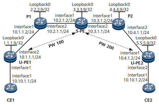
Networking Requirements
As shown in Figure 1, CE1 and CE2 connect to U-PE1 and U-PE2 respectively.
It is required to set up a dynamic PW between U-PE1 and the S-PE, between U-PE2 and the S-PE. An MS-PW is set up between U-PE1 and U-PE2. It is required to configure PW switching on the S-PE.
The MS-PW is required to be carried over an LSP.

Configuring Roadmap
The configuration roadmap is as follows:
Configure the IGP routing protocol for the backbone network, so that devices in the backbone can internetwork with each other.
Configure basic MPLS functions for the backbone, and set up LSP tunnels. Set up MPLS LDP remote peer relationship between U-PE1 and S-PE, and between U-PE2 and S-PE.
Create the PW template, and enable the CW and LSP ping functions.
Set up an MPLS L2VC connection between U-PEs.
Set up a PW switching on the switching node S-PE.
Data Preparation
To complete the configuration, you need the following data:
L2VC ID (The one on U-PE1 differs from that on U-PE2.)
MPLS LSR IDs
Address of the PE remote peer
Encapsulation type of the PW
PW template name and parameters on U-PE
Procedure
- Configure CE.
# Configure CE1.
<HUAWEI> system-view
[~HUAWEI] sysname CE1
[*HUAWEI] commit
[~CE1] interface gigabitethernet 0/1/0
[*CE1-GigabitEthernet0/1/0] ip address 10.10.1.1 24
[*CE1-GigabitEthernet0/1/0] undo shutdown
[*CE1-GigabitEthernet0/1/0] commit
[~CE1-GigabitEthernet0/1/0] quit
# Configure CE2.
<HUAWEI> system-view
[~HUAWEI] sysname CE2
[*HUAWEI] commit
[~CE2] interface gigabitethernet 0/1/0
[*CE2-GigabitEthernet0/1/0] ip address 10.10.1.2 24
[*CE2-GigabitEthernet0/1/0] undo shutdown
[*CE2-GigabitEthernet0/1/0] commit
[~CE2-GigabitEthernet0/1/0] quit
- Configure the IGP for the MPLS backbone network.
Configure the IGP for the MPLS backbone. This example uses OSPF as the IGP.
Configure IP addresses for the interfaces of U-PEs, S-PE, and Ps. While configuring OSPF, advertise the 32-bit loopback addresses of U-PE1, S-PE, and U-PE2.
# Configure U-PE1.
[~U-PE1] interface loopback 0
[*U-PE1-LoopBack0] ip address 1.1.1.9 32
[*U-PE1-LoopBack0] quit
[*U-PE1] interface gigabitethernet 0/1/8
[*U-PE1-GigabitEthernet0/1/8] ip address 10.1.1.1 24
[*U-PE1-GigabitEthernet0/1/8] undo shutdown
[*U-PE1-GigabitEthernet0/1/8] quit
[*U-PE1] ospf 1
[*U-PE1-ospf-1] area 0.0.0.0
[*U-PE1-ospf-1-area-0.0.0.0] network 10.1.1.0 0.0.0.255
[*U-PE1-ospf-1-area-0.0.0.0] network 1.1.1.9 0.0.0.0
[*U-PE1-ospf-1-area-0.0.0.0] quit
[*U-PE1-ospf-1] commit
[~U-PE1-ospf-1] quit
# Configure P1.
[~P1] interface loopback 0
[*P1-LoopBack0] ip address 2.2.2.9 32
[*P1-LoopBack0] quit
[*P1] interface gigabitethernet 1/0/0
[*P1-GigabitEthernet1/0/0] ip address 10.1.1.2 24
[*P1-GigabitEthernet1/0/0] undo shutdown
[*P1-GigabitEthernet1/0/0] quit
[*P1] interface gigabitethernet 2/0/0
[*P1-GigabitEthernet2/0/0] ip address 10.2.1.1 24
[*P1-GigabitEthernet2/0/0] undo shutdown
[*P1-GigabitEthernet2/0/0] quit
[*P1] ospf 1
[*P1-ospf-1] area 0.0.0.0
[*P1-ospf-1-area-0.0.0.0] network 10.1.1.0 0.0.0.255
[*P1-ospf-1-area-0.0.0.0] network 10.2.1.0 0.0.0.255
[*P1-ospf-1-area-0.0.0.0] network 2.2.2.9 0.0.0.0
[*P1-ospf-1-area-0.0.0.0] quit
[*P1-ospf-1] commit
[~P1-ospf-1] quit
# Configure S-PE.
[~S-PE] interface loopback 0
[*S-PE-LoopBack0] ip address 3.3.3.9 32
[*S-PE-LoopBack0] quit
[*S-PE] interface gigabitethernet 1/0/0
[*S-PE-GigabitEthernet1/0/0] ip address 10.2.1.2 24
[*S-PE-GigabitEthernet1/0/0] undo shutdown
[*S-PE-GigabitEthernet1/0/0] quit
[*S-PE] interface gigabitethernet 2/0/0
[*S-PE-GigabitEthernet2/0/0] ip address 10.3.1.1 24
[*S-PE-GigabitEthernet2/0/0] undo shutdown
[*S-PE-GigabitEthernet2/0/0] quit
[*S-PE] ospf 1
[*S-PE-ospf-1] area 0.0.0.0
[*S-PE-ospf-1-area-0.0.0.0] network 10.2.1.0 0.0.0.255
[*S-PE-ospf-1-area-0.0.0.0] network 10.3.1.0 0.0.0.255
[*S-PE-ospf-1-area-0.0.0.0] network 3.3.3.9 0.0.0.0
[*S-PE-ospf-1-area-0.0.0.0] quit
[*S-PE-ospf-1] commit
[~S-PE-ospf-1] quit
# Configure P2
[~P2] interface loopback 0
[*P2-LoopBack0] ip address 4.4.4.9 32
[*P2-LoopBack0] quit
[*P2] interface gigabitethernet 1/0/0
[*P2-GigabitEthernet1/0/0] ip address 10.3.1.2 24
[*P2-GigabitEthernet1/0/0] undo shutdown
[*P2-GigabitEthernet1/0/0] quit
[*P2] interface gigabitethernet 2/0/0
[*P2-GigabitEthernet2/0/0] ip address 10.4.1.1 24
[*P2-GigabitEthernet2/0/0] undo shutdown
[*P2-GigabitEthernet2/0/0] quit
[*P2] ospf 1
[*P2-ospf-1] area 0.0.0.0
[*P2-ospf-1-area-0.0.0.0] network 10.3.1.0 0.0.0.255
[*P2-ospf-1-area-0.0.0.0] network 10.4.1.0 0.0.0.255
[*P2-ospf-1-area-0.0.0.0] network 4.4.4.9 0.0.0.0
[*P2-ospf-1-area-0.0.0.0] quit
[*P2-ospf-1] commit
[~P2-ospf-1] quit
# Configure U-PE2
[~U-PE2] interface loopback 0
[*U-PE2-LoopBack0] ip address 5.5.5.9 32
[*U-PE2-LoopBack0] quit
[*U-PE2] interface gigabitethernet 0/1/0
[*U-PE2-GigabitEthernet0/1/0] ip address 10.4.1.2 24
[*U-PE2-GigabitEthernet0/1/0] undo shutdown
[*U-PE2-GigabitEthernet0/1/0] quit
[*U-PE2] ospf 1
[*U-PE2-ospf-1] area 0.0.0.0
[*U-PE2-ospf-1-area-0.0.0.0] network 10.4.1.0 0.0.0.255
[*U-PE2-ospf-1-area-0.0.0.0] network 5.5.5.9 0.0.0.0
[*U-PE2-ospf-1-area-0.0.0.0] quit
[*U-PE2-ospf-1] commit
[~U-PE2-ospf-1] quit
- Enable MPLS, and set up an LSP and a remote MPLS LDP session.
Configure basic MPLS functions for the backbone, set up tunnels between U-PE1 and S-PE, and between U-PE2s, and create remote LDP sessions.
# Configure U-PE1
[~U-PE1] mpls lsr-id 1.1.1.9
[*U-PE1] mpls
[*U-PE1-mpls] quit
[*U-PE1] mpls ldp
[*U-PE1-mpls-ldp] quit
[*U-PE1] interface gigabitethernet 0/1/8
[*U-PE1-GigabitEthernet0/1/8] mpls
[*U-PE1-GigabitEthernet0/1/8] mpls ldp
[*U-PE1-GigabitEthernet0/1/8] quit
[*U-PE1] mpls ldp remote-peer 3.3.3.9
[*U-PE1-mpls-ldp-remote-3.3.3.9] remote-ip 3.3.3.9
[*U-PE1-mpls-ldp-remote-3.3.3.9] commit
[~U-PE1-mpls-ldp-remote-3.3.3.9] quit
# Configure P1
[~P1] mpls lsr-id 2.2.2.9
[*P1] mpls
[*P1-mpls] quit
[*P1] mpls ldp
[*P1-mpls-ldp] quit
[*P1] interface gigabitethernet 1/0/0
[*P1-GigabitEthernet1/0/0] mpls
[*P1-GigabitEthernet1/0/0] mpls ldp
[*P1-GigabitEthernet1/0/0] quit
[*P1] interface gigabitethernet 2/0/0
[*P1-GigabitEthernet2/0/0] mpls
[*P1-GigabitEthernet2/0/0] mpls ldp
[*P1-GigabitEthernet2/0/0] commit
[~P1-GigabitEthernet2/0/0] quit
# Configure S-PE
[~S-PE] mpls lsr-id 3.3.3.9
[*S-PE] mpls
[*S-PE-mpls] quit
[*S-PE] mpls ldp
[*S-PE-mpls-ldp] quit
[*S-PE] interface gigabitethernet 1/0/0
[*S-PE-GigabitEthernet1/0/0] mpls
[*S-PE-GigabitEthernet1/0/0] mpls ldp
[*S-PE-GigabitEthernet1/0/0] quit
[*S-PE] interface gigabitethernet 2/0/0
[*S-PE-GigabitEthernet2/0/0] mpls
[*S-PE-GigabitEthernet2/0/0] mpls ldp
[*S-PE-GigabitEthernet2/0/0] quit
[*S-PE] mpls ldp remote-peer 1.1.1.9
[*S-PE-mpls-ldp-remote-1.1.1.9] remote-ip 1.1.1.9
[*S-PE-mpls-ldp-remote-1.1.1.9] quit
[*S-PE] mpls ldp remote-peer 5.5.5.9
[*S-PE-mpls-ldp-remote-5.5.5.9] remote-ip 5.5.5.9
[*S-PE-mpls-ldp-remote-5.5.5.9] commit
[~S-PE-mpls-ldp-remote-5.5.5.9] quit
# Configure P2
[~P2] mpls lsr-id 4.4.4.9
[*P2] mpls
[*P2-mpls] quit
[*P2] mpls ldp
[*P2-mpls-ldp] quit
[*P2] interface gigabitethernet 1/0/0
[*P2-GigabitEthernet1/0/0] mpls
[*P2-GigabitEthernet1/0/0] mpls ldp
[*P2-GigabitEthernet1/0/0] quit
[*P2] interface gigabitethernet 2/0/0
[*P2-GigabitEthernet2/0/0] mpls
[*P2-GigabitEthernet2/0/0] mpls ldp
[*P2-GigabitEthernet2/0/0] commit
[~P2-GigabitEthernet2/0/0] quit
# Configure U-PE2
[~U-PE2] mpls lsr-id 5.5.5.9
[*U-PE2] mpls
[*U-PE2-mpls] quit
[*U-PE2] mpls ldp
[*U-PE2-mpls-ldp] quit
[*U-PE2] interface gigabitethernet 0/1/0
[*U-PE2-GigabitEthernet0/1/0] mpls
[*U-PE2-GigabitEthernet0/1/0] mpls ldp
[*U-PE2-GigabitEthernet0/1/0] quit
[*U-PE2] mpls ldp remote-peer 3.3.3.9
[*U-PE2-mpls-ldp-remote-3.3.3.9] remote-ip 3.3.3.9
[*U-PE2-mpls-ldp-remote-3.3.3.9] commit
[~U-PE2-mpls-ldp-remote-3.3.3.9] quit
After the configuration, run the display mpls ldp session command on U-PEs, Ps, or S-PE. The command output shows that the Session State is Operational. Run the display mpls ldp peer command, and you can view how the LDP sessions and the peers have been constructed. Run the display mpls lsp command. The command output shows that LSPs have been constructed. The following example uses the command output on the S-PE.
<S-PE> display mpls ldp session
 LDP Session(s) in Public Network
 Codes: LAM(Label Advertisement Mode), SsnAge Unit(DDDD:HH:MM)
 An asterisk (*) before a session means the session is being deleted.
 ------------------------------------------------------------------------------
 PeerID             Status      LAM  SsnRole  SsnAge      KASent/Rcv
 ------------------------------------------------------------------------------
 1.1.1.9:0          Operational DU   Active   000:00:14   57/57
 2.2.2.9:0          Operational DU   Active   000:00:14   56/56
 4.4.4.9:0          Operational DU   Passive  000:00:05   22/22
 5.5.5.9:0          Operational DU   Passive  000:00:12   52/52
 ------------------------------------------------------------------------------
 TOTAL: 4 session(s) Found.
<S-PE> display mpls ldp peer
 LDP Peer Information in Public network
 An asterisk (*) before a peer means the peer is being deleted.
 ------------------------------------------------------------------------------
 PeerID                TransportAddress   DiscoverySource
 ------------------------------------------------------------------------------
 1.1.1.9:0             1.1.1.9            Remote Peer : 1.1.1.9
 2.2.2.9:0             2.2.2.9            GigabitEthernet1/0/0
 4.4.4.9:0             4.4.4.9            GigabitEthernet2/0/0
 5.5.5.9:0             5.5.5.9            Remote Peer : 5.5.5.9
 ------------------------------------------------------------------------------
 TOTAL: 4 Peer(s) Found.
<S-PE> display mpls lsp
----------------------------------------------------------------------
                 LSP Information: LDP LSP
----------------------------------------------------------------------
FEC                In/Out Label  In/Out IF                      Vrf Name
3.3.3.9/32         3/NULL        -/-
1.1.1.9/32         NULL/1024     -/GigabitEthernet1/0/0
1.1.1.9/32         1024/1024     -/GigabitEthernet1/0/0
2.2.2.9/32         NULL/3        -/GigabitEthernet1/0/0
2.2.2.9/32         1025/3        -/GigabitEthernet1/0/0
4.4.4.9/32         NULL/3        -/GigabitEthernet2/0/0
4.4.4.9/32         1027/3        -/GigabitEthernet2/0/0
5.5.5.9/32         NULL/1027     -/GigabitEthernet2/0/0
5.5.5.9/32         1026/1027     -/GigabitEthernet2/0/0
- Create and configure a PW template.
Create PW templates on U-PEs, and enable the CW and LSP ping functions.
# Configure U-PE1
[~U-PE1] mpls l2vpn
[*U-PE1-l2vpn] quit
[*U-PE1] pw-template pwt
[*U-PE1-pw-template-pwt] peer-address 3.3.3.9
[*U-PE1-pw-template-pwt] control-word
[*U-PE1-pw-template-pwt] commit
[~U-PE1-pw-template-pwt] quit
# Configure U-PE2
[~U-PE2] mpls l2vpn
[*U-PE2-l2vpn] quit
[*U-PE2] pw-template pwt
[*U-PE2-pw-template-pwt] peer-address 3.3.3.9
[*U-PE2-pw-template-pwt] control-word
[*U-PE2-pw-template-pwt] commit
[~U-PE2-pw-template-pwt] quit
- Create a VC connection.
Enable MPLS L2VPN for U-PE1, U-PE2 and the S-PE. Configure the dynamic PW on the U-PE and the dynamic PW switching is performed on the S-PE.
# Configure U-PE1.
[~U-PE1] interface gigabitethernet 0/1/0
[*U-PE1-GigabitEthernet0/1/0] mpls l2vc pw-template pwt 100
[*U-PE1-GigabitEthernet0/1/0] undo shutdown
[*U-PE1-GigabitEthernet0/1/0] commit
[*U-PE1-GigabitEthernet0/1/0] quit
# Configure S-PE.
[*S-PE] mpls l2vpn
[*S-PE-l2vpn] quit
[*S-PE] mpls switch-l2vc 1.1.1.9 100 between 5.5.5.9 200 encapsulation ethernet
[*S-PE] commit
# Configure U-PE2.
[~U-PE2] interface gigabitethernet 0/1/8
[*U-PE2-GigabitEthernet0/1/8] mpls l2vc pw-template pwt 200
[*U-PE2-GigabitEthernet0/1/8] undo shutdown
[*U-PE2-GigabitEthernet0/1/8] commit
[~U-PE2-GigabitEthernet0/1/8] quit
- Verify the configuration.
Check the connection information about PWE3.
Check the connection information about L2VPN on U-PEs and S-PE, and you can see that an L2VC has been set up, whose status is Up.
The following example uses the command output on U-PE1.
<U-PE1> display mpls l2vc interface gigabitethernet 0/1/0
*client interface       : GigabitEthernet0/1/0 is up
  session state          : up
  AC status               : up
  VC state               : up
  Label state            : 0
  Token state            : 0
  VC ID                  : 100
  VC type                : Ethernet
  destination            : 3.3.3.9
  local group ID         : 0            remote group ID      : 0
  local VC label         : 21504        remote VC label      : 21505
  local AC OAM State     : up
  local PSN State        : up
  local forwarding state : forwarding
  local status code      : 0x0
  remote AC OAM state    : up
  remote PSN state       : up
  remote forwarding state: forwarding
  remote status code      : 0x0
  ignore standby state   : no
  BFD for PW             : unavailable
  VCCV State             : up
  manual fault           : not set
  active state           : active
  forwarding entry       : exist
  link state             : up
  local VC MTU           : 4470         remote VC MTU        : 4470
  Local VCCV        : cw alert lsp-ping bfdcw alert ttl lsp-ping bfd
  Remote VCCV       : cw alert lsp-ping bfdcw alert ttl lsp-ping bfd
  local control word     : enable       remote control word  : enable
  tunnel policy name     : --
  traffic behavior name  : --
  PW template name       : pwt
  primary or secondary   : primary
  load balance type      : flow
  Access-port            : false
  Switchover Flag        : false
  VC tunnel/token info   : 1 tunnels/tokens
    NO.0  TNL type : lsp   , TNL ID : 0x2002003
    Backup TNL type      : lsp   , TNL ID : 0x0
  create time            : 0 days, 0 hours, 15 minutes, 3 seconds
  up time                : 0 days, 0 hours, 3 minutes, 15 seconds
  last change time       : 0 days, 0 hours, 3 minutes, 15 seconds
  VC last up time : 2008-07-24 12:31:31
  VC total up time: 0 days, 2 hours, 12 minutes, 51 seconds
  CKey                 : 16
  NKey                 : 15
  PW redundancy mode     : frr
  AdminPw interface      : --
  AdminPw link state     : --
  Forward state        : send inactive, receive inactive
  Diffserv Mode        : uniform
  Service Class        : --
  Color                : --
  DomainId             : --
  Domain Name          : --
View the status of the switching VC on S-PE:
<S-PE> display mpls switch-l2vc
Total Switch VC : 1, 1 up, 0 down
*Switch-l2vc type             : LDP<---->LDP
 Peer IP Address              : 5.5.5.9, 1.1.1.9
 VC ID                        : 200, 100
 VC Type                      : Ethernet
 VC State                     : up
 VC StatusCode                |PSN |OAM | FW |    |PSN |OAM | FW |
                   -Local VC :| UP | UP | UP |    | UP | UP | UP |
                   -Remote VC:| UP | UP | UP |    | UP | UP | UP |
 Session State                : up, up
 Local/Remote Label           : 21504/21504, 21505/21504
 Local/Remote MTU             : 1500/1500, 1500/1500
 Local/Remote Control Word    : Enable/Enable, Enable/Enable
 Local/Remote VCCV Capability : cw alert lsp-ping bfdcw alert ttl lsp-ping bfd/cw alert lsp-ping bfdcw alert ttl lsp-ping bfd, cw alert lsp-ping bfdcw alert ttl lsp-ping bfd/cw alert lsp-ping bfdcw alert ttl lsp-ping bfd
 Switch-l2vc tunnel info      :
                                1 tunnels for peer 5.5.5.9
                                NO.0  TNL Type : lsp   , TNL ID : 0x2002006
                                1 tunnels for peer 1.1.1.9
                                NO.0  TNL Type : lsp   , TNL ID : 0x1002000
 CKey                         : 44, 1
 NKey                         : 43, 3
 Tunnel policy                : --, --
 Create time                  : 0 days, 0 hours, 13 minutes, 1 seconds
 UP time                      : 0 days, 0 hours, 3 minutes, 58 seconds
 Last change time             : 0 days, 0 hours, 3 minutes, 58 seconds
 VC last up time : 2008-07-24 12:31:31
 VC total up time: 0 days, 2 hours, 12 minutes, 51 seconds
Check the connectivity between CEs and the information about the path between CEs.
CE1 and CE2 can ping through each other.
<CE1> ping 10.10.1.2
  PING 10.10.1.2: 56  data bytes, press CTRL_C to break
    Reply from 10.10.1.2: bytes=56 Sequence=1 ttl=255 time=180 ms
    Reply from 10.10.1.2: bytes=56 Sequence=2 ttl=255 time=120 ms
    Reply from 10.10.1.2: bytes=56 Sequence=3 ttl=255 time=160 ms
    Reply from 10.10.1.2: bytes=56 Sequence=4 ttl=255 time=160 ms
    Reply from 10.10.1.2: bytes=56 Sequence=5 ttl=255 time=130 ms
  --- 10.10.1.2 ping statistics ---
    5 packet(s) transmitted
    5 packet(s) received
    0.00% packet loss
    round-trip min/avg/max = 120/150/180 ms
Information about the path from CE1 to CE2.
[~CE1] tracert 10.10.1.2
traceroute to 10.10.1.2 (10.10.1.2), 30 hops max,press CTRL_C to break
traceroute to 10.10.1.2 (10.10.1.2), max hops: 30, packet length: 40, press CTRL_C to break
 1 10.10.1.2 250 ms  220 ms  130 ms
Configuration Files
CE1 configuration file
#
 sysname CE1
#
interface GigabitEthernet0/1/0
 undo shutdown
 ip address 10.10.1.1 255.255.255.0
#
return
U-PE1 configuration file
#
 sysname U-PE1
#
 mpls lsr-id 1.1.1.9
 mpls
#
 mpls l2vpn
#
pw-template pwt
 peer-address 3.3.3.9
 control-word
#
mpls ldp
#
 mpls ldp remote-peer 3.3.3.9
 remote-ip 3.3.3.9
#
interface GigabitEthernet0/1/0
 undo shutdown
 mpls l2vc pw-template pwt 100
#
interface GigabitEthernet0/1/8
 undo shutdown
 ip address 10.1.1.1 255.255.255.0
 mpls
mpls ldp
#
interface LoopBack0
 ip address 1.1.1.9 255.255.255.255
#
ospf 1
 area 0.0.0.0
  network 10.1.1.0 0.0.0.255
  network 1.1.1.9 0.0.0.0
#
return
P1 configuration file
#
 sysname P1
#
 mpls lsr-id 2.2.2.9
 mpls
#
mpls ldp
#
interface GigabitEthernet1/0/0
 undo shutdown
 ip address 10.1.1.2 255.255.255.0
 mpls
 mpls ldp
#
interface GigabitEthernet2/0/0
 undo shutdown
 ip address 10.2.1.1 255.255.255.0
 mpls
 mpls ldp
#
interface LoopBack0
 ip address 2.2.2.9 255.255.255.255
#
ospf 1
 area 0.0.0.0
  network 2.2.2.9 0.0.0.0
  network 10.1.1.0 0.0.0.255
  network 10.2.1.0 0.0.0.255
#
return
S-PE configuration file
#
 sysname S-PE
#
 mpls lsr-id 3.3.3.9
 mpls
#
 mpls l2vpn
#
 mpls switch-l2vc 5.5.5.9 200 between 1.1.1.9 100 encapsulation ethernet
#
mpls ldp
#
 mpls ldp remote-peer 1.1.1.9
 remote-ip 1.1.1.9
#
 mpls ldp remote-peer 5.5.5.9
 remote-ip 5.5.5.9
#
interface GigabitEthernet1/0/0
 undo shutdown
 ip address 10.2.1.2 255.255.255.0
 mpls
 mpls ldp
#
interface GigabitEthernet2/0/0
 undo shutdown
 ip address 10.3.1.1 255.255.255.0
 mpls
 mpls ldp
#
interface LoopBack0
 ip address 3.3.3.9 255.255.255.255
#
ospf 1
 area 0.0.0.0
  network 3.3.3.9 0.0.0.0
  network 10.2.1.0 0.0.0.255
  network 10.3.1.0 0.0.0.255
#
return
P2 configuration file
#
 sysname P2
#
 mpls lsr-id 4.4.4.9
 mpls
#
mpls ldp
#
interface GigabitEthernet1/0/0
 undo shutdown
 ip address 10.3.1.2 255.255.255.0
 mpls
 mpls ldp
#
interface GigabitEthernet2/0/0
 undo shutdown
 ip address 10.4.1.1 255.255.255.0
 mpls
 mpls ldp
#
interface LoopBack0
 ip address 4.4.4.9 255.255.255.255
#
ospf 1
 area 0.0.0.0
  network 4.4.4.9 0.0.0.0
  network 10.3.1.0 0.0.0.255
  network 10.4.1.0 0.0.0.255
#
return
U-PE2 configuration file
#
 sysname U-PE2
#
 mpls lsr-id 5.5.5.9
 mpls
#
 mpls l2vpn
#
pw-template pwt
 peer-address 3.3.3.9
 control-word
#
mpls ldp
#
 mpls ldp remote-peer 3.3.3.9
 remote-ip 3.3.3.9
#
interface GigabitEthernet0/1/0
 undo shutdown
 ip address 10.4.1.2 255.255.255.0
 mpls
 mpls ldp
#
interface GigabitEthernet0/1/8
 undo shutdown
 mpls l2vc pw-template pwt 200
#
interface LoopBack0
 ip address 5.5.5.9 255.255.255.255
#
ospf 1
 area 0.0.0.0
  network 5.5.5.9 0.0.0.0
  network 10.4.1.0 0.0.0.255
#
return
CE2 configuration file
#
 sysname CE2
#
interface GigabitEthernet0/1/0
 undo shutdown
 ip address 10.10.1.2 255.255.255.0
#
return