Example for Configuring BFD for VPWS PW
Using BFD to detect PW faults involves simple configurations and requires a few packet exchanges.
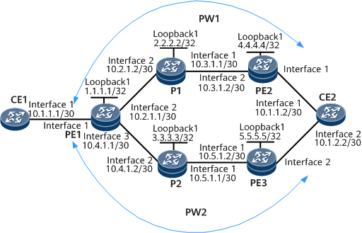
Networking Requirements
On the Multiprotocol Label Switching (MPLS) Layer 2 virtual private network (L2VPN):
PW1 is established between PE1 and PE2 and serves as the primary PW.
PW2 is established between PE1 and PE3 and serves as the secondary PW.
On the network shown in Figure 1, BFD needs to be configured to monitor the connectivity of the primary and secondary PWs, so that services can switch to the secondary PW within 50 ms if the primary PW fails.
Configuration Roadmap
The configuration roadmap is as follows:
Configure MPLS capabilities.
Establish PW1 between PE1 and PE2 and PW2 between PE1 and PE3. Configure PW1 as the primary PW and PW2 as the secondary PW on AC interfaces of PE1.
Configure BFD to monitor the connectivity of PW1 and PW2.
Data Preparation
To complete the configuration, you need the following data:
IP addresses of interfaces
VC IDs of PWs
Names and the local and remote discriminators of BFD sessions
Procedure
- Assign IP addresses to CE interfaces that connect to PEs.
# Configure CE1.
<HUAWEI> system-view
[~HUAWEI] sysname CE1
[*CE1] commit
[~CE1] interface gigabitethernet 0/1/0
[*CE1-GigabitEthernet0/1/0] ip address 10.1.1.1 30
[*CE1-GigabitEthernet0/1/0] ip address 10.1.2.1 30 sub
[*CE1-GigabitEthernet0/1/0] undo shutdown
[*CE1-GigabitEthernet0/1/0] commit
[~CE1-GigabitEthernet0/1/0] quit
# Configure CE2.
<HUAWEI> system-view
[~HUAWEI] sysname CE2
[*CE2] commit
[~CE2] interface gigabitethernet 0/1/0
[*CE2-GigabitEthernet0/1/0] ip address 10.1.1.2 30
[*CE2-GigabitEthernet0/1/0] undo shutdown
[*CE2-GigabitEthernet0/1/0] quit
[*CE2] interface gigabitethernet 0/1/1
[*CE2-GigabitEthernet0/1/1] ip address 10.1.2.2 30
[*CE2-GigabitEthernet0/1/1] undo shutdown
[*CE2-GigabitEthernet0/1/1] commit
[~CE2-GigabitEthernet0/1/1] quit
- Configure an IGP (OSPF is used as an example) on the MPLS backbone network so that PEs and Ps can communicate.
# Configure PE1.
[~PE1] interface loopback 1
[*PE1-LoopBack1] ip address 1.1.1.1 32
[*PE1-LoopBack1] quit
[*PE1] interface gigabitethernet 0/1/1
[*PE1-GigabitEthernet0/1/1] ip address 10.2.1.1 30
[*PE1-GigabitEthernet0/1/1] undo shutdown
[*PE1-GigabitEthernet0/1/1] quit
[*PE1] interface gigabitethernet 0/1/2
[*PE1-GigabitEthernet0/1/2] ip address 10.4.1.1 30
[*PE1-GigabitEthernet0/1/2] undo shutdown
[*PE1-GigabitEthernet0/1/2] quit
[*PE1] commit
[~PE1] ospf 1
[*PE1-ospf-1] area 0
[*PE1-ospf-1-area-0.0.0.0] network 1.1.1.1 0.0.0.0
[*PE1-ospf-1-area-0.0.0.0] network 10.2.1.0 0.0.0.3
[*PE1-ospf-1-area-0.0.0.0] network 10.4.1.0 0.0.0.3
[*PE1-ospf-1-area-0.0.0.0] quit
[*PE1] commit
# Configure P1.
[~P1] interface loopback 1
[*P1-LoopBack1] ip address 2.2.2.2 32
[*P1-LoopBack1] quit
[*P1] interface gigabitethernet 0/1/0
[*P1-GigabitEthernet0/1/0] ip address 10.3.1.1 30
[*P1-GigabitEthernet0/1/0] undo shutdown
[*P1-GigabitEthernet0/1/0] quit
[*P1] interface gigabitethernet 0/1/1
[*P1-GigabitEthernet0/1/1] ip address 10.2.1.2 30
[*P1-GigabitEthernet0/1/1] undo shutdown
[*P1-GigabitEthernet0/1/1] quit
[*P1] commit
[~P1] ospf 1
[*P1-ospf-1] area 0
[*P1-ospf-1-area-0.0.0.0] network 2.2.2.2 0.0.0.0
[*P1-ospf-1-area-0.0.0.0] network 10.2.1.0 0.0.0.3
[*P1-ospf-1-area-0.0.0.0] network 10.3.1.0 0.0.0.3
[*P1-ospf-1-area-0.0.0.0] quit
[*P1] commit
# Configure P2.
[~P2] interface loopback 1
[*P2-LoopBack1] ip address 3.3.3.3 32
[*P2-LoopBack1] quit
[*P2] interface gigabitethernet 0/1/0
[*P2-GigabitEthernet0/1/0] ip address 10.5.1.1 30
[*P2-GigabitEthernet0/1/0] undo shutdown
[*P2-GigabitEthernet0/1/0] quit
[*P2] interface gigabitethernet 0/1/1
[*P2-GigabitEthernet0/1/1] ip address 10.4.1.2 30
[*P2-GigabitEthernet0/1/1] undo shutdown
[*P2-GigabitEthernet0/1/1] quit
[*P2] commit
[~P2] ospf 1
[*P2-ospf-1] area 0
[*P2-ospf-1-area-0.0.0.0] network 3.3.3.3 0.0.0.0
[*P2-ospf-1-area-0.0.0.0] network 10.4.1.0 0.0.0.3
[*P2-ospf-1-area-0.0.0.0] network 10.5.1.0 0.0.0.3
[*P2-ospf-1-area-0.0.0.0] quit
[*P2] commit
# Configure PE2.
[~PE2] interface loopback 1
[*PE2-LoopBack1] ip address 4.4.4.4 32
[*PE2-LoopBack1] quit
[*PE2] interface gigabitethernet 0/1/1
[*PE2-GigabitEthernet0/1/1] ip address 10.3.1.2 30
[*PE2-GigabitEthernet0/1/1] undo shutdown
[*PE2-GigabitEthernet0/1/1] quit
[*PE2] commit
[~PE2] ospf 1
[*PE2-ospf-1] area 0
[*PE2-ospf-1-area-0.0.0.0] network 4.4.4.4 0.0.0.0
[*PE2-ospf-1-area-0.0.0.0] network 10.3.1.0 0.0.0.3
[*PE2-ospf-1-area-0.0.0.0] quit
[*PE2] commit
# Configure PE3.
[*PE3] interface loopback 1
[*PE3-LoopBack1] ip address 5.5.5.5 32
[*PE3-LoopBack1] quit
[*PE3] interface gigabitethernet0/1/0
[*PE3-GigabitEthernet0/1/0] ip address 10.5.1.2 30
[*PE3-GigabitEthernet0/1/0] undo shutdown
[*PE3-GigabitEthernet0/1/0] quit
[*PE3] commit
[~PE3] ospf 1
[*PE3-ospf-1] area 0
[*PE3-ospf-1-area-0.0.0.0] network 5.5.5.5 0.0.0.0
[*PE3-ospf-1-area-0.0.0.0] network 10.5.1.0 0.0.0.3
[*PE3-ospf-1-area-0.0.0.0] quit
[*PE3] commit
After completing the configurations, run the display ip routing-table command on each PE. The command output shows that PE1 and PE2 have learned the routes to each other's Loopback1 interface, and PE1 and PE3 have learned the routes to each other's Loopback1 interface.
The following example uses the command output on PE1.
<PE1> display ip routing-table
Route Flags: R - relay, D - download to fib, T - to vpn-instance, B - black hole route
------------------------------------------------------------------------------
Routing Table: Public
         Destinations : 15       Routes : 15
Destination/Mask    Proto  Pre  Cost     Flags NextHop         Interface
        1.1.1.1/32  Direct 0    0           D  127.0.0.1       InLoopBack0
        2.2.2.2/32  OSPF   10   2           D  10.2.1.2       GigabitEthernet0/1/1
        3.3.3.3/32  OSPF   10   2           D  10.4.1.2       GigabitEthernet0/1/2
        4.4.4.4/32  OSPF   10   3           D  10.2.1.2       GigabitEthernet0/1/1
        5.5.5.5/32  OSPF   10   3           D  10.4.1.2       GigabitEthernet0/1/2
      10.2.1.0/30  Direct 0    0           D  10.2.1.1       GigabitEthernet0/1/1
      10.2.1.1/32  Direct 0    0           D  127.0.0.1       InLoopBack0
      10.2.1.2/32  Direct 0    0           D  10.2.1.2       GigabitEthernet0/1/1
      10.3.1.0/30  OSPF   10   2           D  10.2.1.2       GigabitEthernet0/1/1
      127.0.0.0/8   Direct 0    0           D  127.0.0.1       InLoopBack0
      127.0.0.1/32  Direct 0    0           D  127.0.0.1       InLoopBack0
      10.4.1.0/30  Direct 0    0           D  10.4.1.1       GigabitEthernet0/1/2
      10.4.1.1/32  Direct 0    0           D  127.0.0.1       InLoopBack0
      10.4.1.2/32  Direct 0    0           D  10.4.1.2       GigabitEthernet0/1/2
      10.5.1.0/30  OSPF   10   2           D  10.4.1.2       GigabitEthernet0/1/2
- Configure basic MPLS functions on the MPLS backbone network.
# Enable MPLS and configure the Loopback1 address as an LSR ID on each involved device. Enable MPLS and MPLS LDP on involved interfaces connected to the MPLS backbone network.
# Configure PE1.
[~PE1] mpls lsr-id 1.1.1.1
[*PE1] mpls
[*PE1-mpls] quit
[*PE1] mpls ldp
[*PE1-mpls-ldp] quit
[*PE1] interface gigabitethernet0/1/1
[*PE1-GigabitEthernet0/1/1] mpls
[*PE1-GigabitEthernet0/1/1] mpls ldp
[*PE1-GigabitEthernet0/1/1] quit
[*PE1] interface gigabitethernet0/1/2
[*PE1-GigabitEthernet0/1/2] mpls
[*PE1-GigabitEthernet0/1/2] mpls ldp
[*PE1-GigabitEthernet0/1/2] commit
[~PE1-GigabitEthernet0/1/2] quit
# Configure P1.
[~P1] mpls lsr-id 2.2.2.2
[*P1] mpls
[*P1-mpls] quit
[*P1] mpls ldp
[*P1-mpls-ldp] quit
[*P1] interface gigabitethernet 0/1/0
[*P1-GigabitEthernet0/1/0] mpls
[*P1-GigabitEthernet0/1/0] mpls ldp
[*P1-GigabitEthernet0/1/0] quit
[*P1] interface gigabitethernet 0/1/1
[*P1-GigabitEthernet0/1/1] mpls
[*P1-GigabitEthernet0/1/1] mpls ldp
[*P1-GigabitEthernet0/1/1] commit
[~P1-GigabitEthernet0/1/1] quit
# Configure P2.
[~P2] mpls lsr-id 3.3.3.3
[*P2] mpls
[*P2-mpls] quit
[*P2] mpls ldp
[*P2-mpls-ldp] quit
[*P2] interface gigabitethernet 0/1/0
[*P1-GigabitEthernet0/1/0] mpls
[*P1-GigabitEthernet0/1/0] mpls ldp
[*P1-GigabitEthernet0/1/0] quit
[*P2] interface gigabitethernet 0/1/1
[*P1-GigabitEthernet0/1/1] mpls
[*P1-GigabitEthernet0/1/1] mpls ldp
[*P1-GigabitEthernet0/1/1] commit
[~P1-GigabitEthernet0/1/1] quit
# Configure PE2.
[~PE2] mpls lsr-id 4.4.4.4
[*PE2] mpls
[*PE2-mpls] quit
[*PE2] mpls ldp
[*PE2-mpls-ldp] quit
[*PE2] interface gigabitethernet 0/1/1
[*PE2-GigabitEthernet0/1/1] mpls
[*PE2-GigabitEthernet0/1/1] mpls ldp
[*PE2-GigabitEthernet0/1/1] commit
[~PE2-GigabitEthernet0/1/1] quit
# Configure PE3.
[~PE3] mpls lsr-id 5.5.5.5
[*PE3] mpls
[*PE3-mpls] quit
[*PE3] mpls ldp
[*PE3-mpls-ldp] quit
[*PE3] interface gigabitethernet 0/1/0
[*PE3-GigabitEthernet0/1/0] mpls
[*PE3-GigabitEthernet0/1/0] mpls ldp
[*PE3-GigabitEthernet0/1/0] commit
[~PE3-GigabitEthernet0/1/0] quit
After completing the configurations, run the display tunnel-info all command each PE. The command output shows that an MPLS LSP has been established between PE1 and PE2 and between PE1 and PE3.
The following example uses the command output on PE1.
<PE1> display tunnel-info all
Tunnel ID               Type              Destination          Status
----------------------------------------------------------------------
0x000000000300000000    ldp               2.2.2.2              UP
0x000000000300000001    ldp               --                   UP
0x000000000300000002    ldp               3.3.3.3              UP
0x000000000300000003    ldp               --                   UP
0x000000000300000004    ldp               4.4.4.4              UP
0x000000000300000005    ldp               --                   UP
0x000000000300000006    ldp               5.5.5.5              UP
0x000000000300000007    ldp               --                   UP
Run the display mpls ldp session command on each PE. The command output shows that the Status field is Operational, indicating that an LDP peer relationship has been established between this PE and its neighboring P.
The following example uses the command output on PE1.
<PE1> display mpls ldp session LDP Session(s) in Public Network Codes: LAM(Label Advertisement Mode), SsnAge Unit(DDDD:HH:MM) An asterisk (*) before a session means the session is being deleted. ------------------------------------------------------------------------------ PeerID Status LAM SsnRole SsnAge KASent/Rcv ------------------------------------------------------------------------------ 2.2.2.2:0 Operational DU Passive 000:00:03 16/16 3.3.3.3:0 Operational DU Passive 000:00:03 13/13 ------------------------------------------------------------------------------ TOTAL: 2 session(s) Found. - Establish a remote LDP session between PE1 and PE2.
# Configure a remote LDP session, and use the loopback interface address of a remote LDP peer as the remote peer address.

If two PEs are directly connected, you do not need to configure a remote LDP session between them.
# Configure PE1.
[~PE1] mpls ldp remote-peer 4.4.4.4
[*PE1-mpls-ldp-remote-4.4.4.4] remote-ip 4.4.4.4
[*PE1-mpls-ldp-remote-4.4.4.4] quit
[*PE1] mpls ldp remote-peer 5.5.5.5
[*PE1-mpls-ldp-remote-5.5.5.5] remote-ip 5.5.5.5
[*PE1-mpls-ldp-remote-5.5.5.5] commit
[~PE1-mpls-ldp-remote-5.5.5.5] quit
# Configure PE2.
[~PE2] mpls ldp remote-peer 1.1.1.1
[*PE2-mpls-ldp-remote-1.1.1.1] remote-ip 1.1.1.1
[*PE2-mpls-ldp-remote-1.1.1.1] commit
[~PE2-mpls-ldp-remote-1.1.1.1] quit
# Configure PE3.
[~PE3] mpls ldp remote-peer 1.1.1.1
[*PE3-mpls-ldp-remote-1.1.1.1] remote-ip 1.1.1.1
[*PE3-mpls-ldp-remote-1.1.1.1] commit
[~PE3-mpls-ldp-remote-1.1.1.1] quit
After completing the configurations, run the display mpls ldp session command on each PE. The command output shows that the Status field is Operational, indicating that a remote LDP peer relationship has been established.
The following example uses the command output on PE1.
<PE1> display mpls ldp session LDP Session(s) in Public Network Codes: LAM(Label Advertisement Mode), SsnAge Unit(DDDD:HH:MM) An asterisk (*) before a session means the session is being deleted. ------------------------------------------------------------------------------ PeerID Status LAM SsnRole SsnAge KASent/Rcv ------------------------------------------------------------------------------ 2.2.2.2:0 Operational DU Passive 000:00:06 27/27 3.3.3.3:0 Operational DU Passive 000:00:05 24/24 4.4.4.4:0 Operational DU Passive 000:00:00 3/3 5.5.5.5:0 Operational DU Passive 000:00:00 2/2 ------------------------------------------------------------------------------ TOTAL: 4 session(s) Found. - Configure PWs on PEs using PW templates.
# Configure PE1.
[~PE1] mpls l2vpn
[*PE1-l2vpn] quit
[*PE1] pw-template 1to2
[*PE1-pw-template-1to2] peer-address 4.4.4.4
[*PE1-pw-template-1to2] control-word
[*PE1-pw-template-1to2] quit
[*PE1] pw-template 1to3
[*PE1-pw-template-1to3] peer-address 5.5.5.5
[*PE1-pw-template-1to3] control-word
[*PE1-pw-template-1to3] quit
[*PE1] interface gigabitethernet0/1/0
[*PE1-GigabitEthernet0/1/0] mpls l2vc pw-template 1to2 100
[*PE1-GigabitEthernet0/1/0] mpls l2vc pw-template 1to3 200 secondary
[*PE1-GigabitEthernet0/1/0] undo shutdown
[*PE1-GigabitEthernet0/1/0] commit
[~PE1-GigabitEthernet0/1/0] quit
# Configure PE2.
[~PE2] mpls l2vpn
[*PE2-l2vpn] quit
[*PE2] pw-template 2to1
[*PE2-pw-template-2to1] peer 1.1.1.1
[*PE2-pw-template-2to1] control-word
[*PE2-pw-template-2to1] quit
[*PE2] interface gigabitethernet 0/1/0
[*PE2-GigabitEthernet0/1/0] mpls l2vc pw-template 2to1 100
[*PE2-GigabitEthernet0/1/0] undo shutdown
[*PE2-GigabitEthernet0/1/0] commit
[~PE2-GigabitEthernet0/1/0] quit
# Configure PE3.
[~PE3] mpls l2vpn
[*PE3-l2vpn] quit
[*PE3] pw-template 3to1
[*PE3-pw-template-3to1] peer 1.1.1.1
[*PE3-pw-template-3to1] control-word
[*PE3-pw-template-3to1] quit
[*PE3] interface gigabitethernet 0/1/1
[*PE3-GigabitEthernet0/1/1] mpls l2vc pw-template 3to1 200
[*PE3-GigabitEthernet0/1/1] undo shutdown
[*PE3-GigabitEthernet0/1/1] commit
[~PE3-GigabitEthernet0/1/1] quit
After completing the configurations, run the display pw-template command on each PE. The command output shows PW template configurations.
The following example uses the command output on PE1.
<PE1> display pw-template
 Total PW template number : 2

  PW Template Name : 1to2
  PeerIP           : 4.4.4.4
  Tnl Policy Name  : --
  CtrlWord         : Enable
  MTU              : 1500
  Seq-Number       : Disable
  TDM Encapsulation Number: 32
  Jitter-Buffer           : 20
  Jitter-Buffer-Cep       : 1125   Payload-Compression DBA : UNEQ
  Idle-Code               : ff
  Rtp-Header              : Disable
  VCCV Capability  : cw alert lsp-ping bfd
  Behavior Name    : --
  Total PW         : 1, Static PW : 0, LDP PW : 1

  PW Template Name : 1to3
  PeerIP           : 5.5.5.5
  Tnl Policy Name  : --
  CtrlWord         : Enable
  MTU              : 1500
  Seq-Number       : Disable
  TDM Encapsulation Number: 32
  Jitter-Buffer           : 20
  Jitter-Buffer-Cep       : 1125   Payload-Compression DBA : UNEQ
  Idle-Code               : ff
  Rtp-Header              : Disable
  VCCV Capability  : cw alert lsp-ping bfd
  Behavior Name    : --
  Total PW         : 1, Static PW : 0, LDP PW : 1
After completing the configurations, run the display mpls l2vc interface command on each PE. The command output shows that PWs have been established and are in the Active state, and that BFD for PW is not configured for the primary and secondary PWs.
The following example uses the command output on PE1.
<PE1> display mpls l2vc interface gigabitethernet 0/1/0
*client interface       : GigabitEthernet0/1/0 is up
  session state          : up
  AC status               : up
  VC state               : up
  VC ID                  : 100
  VC type                : PPP
  destination            : 4.4.4.4
  local group ID         : 0            remote group ID      : 0
  local VC label         : 21504        remote VC label      : 21504
  local AC OAM State     : up
  local PSN State        : up
  local forwarding state : forwarding
  local status code      : 0x0
  remote AC OAM state    : up
  remote PSN state       : up
  remote forwarding state: forwarding
  remote statuscode      : 0x0
  BFD for PW             : unavailable
  manual fault           : not set
  active state           : active
  forwarding entry       : exist
  link state             : up
  local VC MTU           : 4470         remote VC MTU        : 4470
  Local VCCV        : cw alert lsp-ping bfd
  Remote VCCV       : cw alert lsp-ping bfd
  local control word     : enable       remote control word  : enable
  tunnel policy name     : --
  traffic behavior name  : --
  PW template name       : 1to2
  primary or secondary   : primary
  VC tunnel/token info   : 1 tunnels/tokens
    NO.0  TNL type : lsp   , TNL ID : 0x1002004
  create time            : 0 days, 1 hours, 22 minutes, 22 seconds
  up time                : 0 days, 1 hours, 21 minutes, 14 seconds
  last change time       : 0 days, 1 hours, 21 minutes, 14 seconds
  VC last up time : 2008-07-24 12:31:31
  VC total up time: 0 days, 2 hours, 12 minutes, 51 seconds
  CKey                 : 16
  NKey                 : 15
 *client interface       : GigabitEthernet0/1/0 is up
  session state          : up
  AC status               : up
  VC state               : up
  VC ID                  : 200
  VC type                : PPP
  destination            : 5.5.5.5
  local group ID         : 0            remote group ID      : 0
  local VC label         : 21505        remote VC label      : 21504
  local AC OAM state     : up
  local PSN state        : up
  local forwarding state : forwarding
  local status code      : 0x0
  remote AC OAM state    : up
  remote PSN state       : up
  remote forwarding state: forwarding
  remote statuscode      : 0x0
  BFD for PW             : unavailable
  manual fault           : not set
  active state           : inactive
  forwarding entry       : existent
  link state             : up
  local VC MTU           : 4470         remote VC MTU        : 4470
  Local VCCV        : cw alert lsp-ping bfd
  Remote VCCV       : cw alert lsp-ping bfd
  local control word     : enable       remote control word : enable
  tunnel policy          : --
  traffic behavior       : --
  PW template name       : 1to3
  primary or secondary   : secondary
  VC tunnel/token info   : 1 tunnels/tokens
    NO.0  TNL type : lsp   , TNL ID : 0x1002006
  create time            : 0 days, 1 hours, 22 minutes, 9 seconds
  up time                : 0 days, 1 hours, 20 minutes, 22 seconds
  last change time       : 0 days, 1 hours, 20 minutes, 22 seconds
  VC last up time : 2008-07-24 12:31:31
  VC total up time: 0 days, 2 hours, 12 minutes, 51 seconds
  CKey                 : 17
  NKey                 : 18
 reroute policy          : delay 30 s, resume 10 s
 reason of last reroute  : --
 time of last reroute    : -- days, -- hours, -- minutes, -- seconds
 delay timer ID          : --           residual time :--
 resume timer ID         : --           residual time :--
- Configure BFD for VPWS PW on PEs.
Currently, static BFD and dynamic BFD are supported. For the same VPWS PW, the static BFD session and dynamic BFD session are mutually exclusive. That is, only a single type of BFD session can be configured.
In this example, the configuration static BFD for VPWS PW is displayed in the configuration file.
- Configure static BFD.
For a BFD session, the local discriminator on one end must be the same as the remote discriminator on the other end.
# Configure PE1.
[~PE1] bfd
[*PE1-bfd] quit
[*PE1] bfd 1to2 bind pw interface gigabitethernet 0/1/0
[*PE1-bfd-lsp-session-1to2] discriminator local 12
[*PE1-bfd-lsp-session-1to2] discriminator remote 21
[*PE1-bfd-lsp-session-1to2] commit
[~PE1-bfd-lsp-session-1to2] quit
[*PE1] bfd 1to3 bind pw interface gigabitethernet 0/1/0 secondary
[*PE1-bfd-lsp-session-1to3] discriminator local 13
[*PE1-bfd-lsp-session-1to3] discriminator remote 31
[*PE1-bfd-lsp-session-1to3] commit
[~PE1-bfd-lsp-session-1to3] quit
# Configure PE2.
[~PE2] bfd
[*PE2-bfd] quit
[*PE2] bfd 2to1 bind pw interface gigabitethernet 0/1/0
[*PE2-bfd-lsp-session-2to1] discriminator local 21
[*PE2-bfd-lsp-session-2to1] discriminator remote 12
[*PE2-bfd-lsp-session-2to1] commit
[~PE2-bfd-lsp-session-2to1] quit
# Configure PE3.
[~PE3] bfd
[*PE3-bfd] quit
[*PE3] bfd 3to1 bind pw interface gigabitethernet 0/1/1
[*PE3-bfd-lsp-session-3to1] discriminator local 31
[*PE3-bfd-lsp-session-3to1] discriminator remote 13
[*PE3-bfd-lsp-session-3to1] commit
[~PE3-bfd-lsp-session-3to1] quit
After the configuration is complete, BFD sessions can be created between PE1 and PE2, and between PE1 and PE3. Run the display bfd session all command. The command output shows that the BFD state field is up.
The following example uses the command output on PE1.
<PE1> display bfd session all
(w): State in WTR
(*): State is invalid
--------------------------------------------------------------------------------
Local  Remote PeerIpAddr                     State     Type       InterfaceName
--------------------------------------------------------------------------------
12     21     --.--.--.--                     Up        S_PW(M)    GigabitEthernet0/1/0
13     31     --.--.--.--                     Up        S_PW(S)    GigabitEthernet0/1/0
--------------------------------------------------------------------------------
     Total UP/DOWN Session Number : 2/0
- Configure dynamic BFD.
# Configure PE1.
[~PE1] bfd
[*PE1-bfd] quit
[*PE1] pw-template 1to2
[*PE1-pw-template-1to2] control-word
[*PE1-pw-template-1to2] bfd-detect min-rx-interval 100 min-tx-interval 100 detect-multiplier 4
[*PE1-pw-template-1to2] quit
[*PE1] pw-template 1to3
[*PE1-pw-template-1to3] control-word
[*PE1-pw-template-1to3] bfd-detect min-rx-interval 100 min-tx-interval 100 detect-multiplier 4
[*PE1-pw-template-1to3] quit
[*PE1] interface gigabitethernet 0/1/0
[*PE1-GigabitEthernet0/1/0] mpls l2vpn pw bfd min-rx-interval 100 min-tx-interval 100 detect-multiplier 4
[*PE1-GigabitEthernet0/1/0] mpls l2vpn pw bfd min-rx-interval 100 min-tx-interval 100 detect-multiplier 4 secondary
[*PE1-GigabitEthernet0/1/0] commit
[*PE1-GigabitEthernet0/1/0] quit
# Configure PE2.
[~PE2] bfd
[*PE2-bfd] quit
[*PE2] pw-template 2to1
[*PE2-pw-template-2to1] control-word
[*PE2-pw-template-2to1] bfd-detect min-rx-interval 100 min-tx-interval 100 detect-multiplier 4
[*PE2-pw-template-2to1] quit
[*PE2] interface gigabitethernet 0/1/0
[*PE2-GigabitEthernet0/1/0] mpls l2vpn pw bfd min-rx-interval 100 min-tx-interval 100 detect-multiplier 4 track-interface
[*PE2-GigabitEthernet0/1/0] commit
[*PE2-GigabitEthernet0/1/0] quit
# Configure PE3.
[~PE3] bfd
[*PE3-bfd] quit
[*PE3] pw-template 3to1
[*PE3-pw-template-3to1] control-word
[*PE3-pw-template-3to1] bfd-detect min-rx-interval 100 min-tx-interval 100 detect-multiplier 4
[*PE3-pw-template-3to1] quit
[*PE3] interface gigabitethernet 0/1/1
[*PE3-GigabitEthernet0/1/1] mpls l2vpn pw bfd min-rx-interval 100 min-tx-interval 100 detect-multiplier 4 track-interface
[*PE3-GigabitEthernet0/1/1] commit
[*PE3-GigabitEthernet0/1/1] quit
After the configuration is complete, BFD sessions can be created between PE1 and PE2, and between PE1 and PE3. Run the display bfd session all command. The command output shows that the BFD state field is up.
The following example uses the command output on PE1.
<PE1> display bfd session all
(w): State in WTR
(*): State is invalid
--------------------------------------------------------------------------------
Local  Remote PeerIpAddr                     State     Type       InterfaceName
--------------------------------------------------------------------------------
12     21     --.--.--.--                     Up        D_PW(M)    GigabitEthernet0/1/0
13     31     --.--.--.--                     Up        D_PW(S)    GigabitEthernet0/1/0
--------------------------------------------------------------------------------
     Total UP/DOWN Session Number : 2/0
- Configure static BFD.
- Verify the configuration.
Verify the configuration of static BFD for VPWS PW. The procedure for verifying dynamic BFD for VPWS PW is similar to that for verifying static BFD for VPWS PW.
When the primary PW is working properly, CE1 can use the primary address to ping CE2's 10.1.1.2. Because the secondary PW does not work, CE1 cannot use the secondary address to ping CE2's 10.1.2.2.
<CE1> ping 10.1.1.2
  PING 10.1.1.2: 56  data bytes, press CTRL_C to break
    Reply from 10.1.1.2: bytes=56 Sequence=1 ttl=255 time=140 ms
    Reply from 10.1.1.2: bytes=56 Sequence=2 ttl=255 time=90 ms
    Reply from 10.1.1.2: bytes=56 Sequence=3 ttl=255 time=120 ms
    Reply from 10.1.1.2: bytes=56 Sequence=4 ttl=255 time=120 ms
    Reply from 10.1.1.2: bytes=56 Sequence=5 ttl=255 time=130 ms
  --- 10.1.1.2 ping statistics ---
    5 packet(s) transmitted
    5 packet(s) received
    0.00% packet loss
    round-trip min/avg/max = 90/120/140 ms
<CE1> ping 10.1.2.2
  PING 10.1.2.2: 56  data bytes, press CTRL_C to break
    Request time out
    Request time out
    Request time out
    Request time out
    Request time out
  --- 10.1.2.2 ping statistics ---
    5 packet(s) transmitted
    0 packet(s) received
    100.00% packet loss
# Run the display mpls l2vc interface command on each PE. The command output shows that the BFD for PW field is available, and the BFD state field is up for both the primary and secondary PWs.
<PE1> display mpls l2vc interface gigabitethernet 0/1/0
*client interface       : GigabitEthernet0/1/0 is up
  session state          : up
  AC status               : up
  VC state               : up
  VC ID                  : 100
  VC type                : Ethernet
  destination            : 4.4.4.4
  local group ID         : 0            remote group ID      : 0
  local VC label         : 21504        remote VC label      : 21504
  local AC OAM State     : up
  local PSN State        : up
  local forwarding state : forwarding
  local status code      : 0x0
  remote AC OAM state    : up
  remote PSN state       : up
  remote forwarding state: forwarding
  remote statuscode      : 0x0
  BFD for PW             : available
    BFD sessionIndex     : 256          BFD state : up
  manual fault           : not set
  active state           : active
  forwarding entry       : exist
  link state             : up
  local VC MTU           : 4470         remote VC MTU        : 4470
  Local VCCV        : cw alert lsp-ping bfd
  Remote VCCV       : cw alert lsp-ping bfd
  local control word     : enable       remote control word  : enable
  tunnel policy name     : --
  traffic behavior name  : --
  PW template name       : 1to2
  primary or secondary   : primary
  VC tunnel/token info   : 1 tunnels/tokens
    NO.0  TNL type : lsp   , TNL ID : 0x1002004
  create time            : 0 days, 1 hours, 17 minutes, 55 seconds
  up time                : 0 days, 1 hours, 16 minutes, 47 seconds
  last change time       : 0 days, 1 hours, 16 minutes, 47 seconds
  VC last up time : 2008-07-24 12:31:31
  VC total up time: 0 days, 2 hours, 12 minutes, 51 seconds
  CKey                 : 16
  NKey                 : 15
 *client interface       : GigabitEthernet0/1/0 is up
  session state          : up
  AC status               : up
  VC state               : up
  VC ID                  : 200
  VC type                : Ethernet
  destination            : 5.5.5.5
  local group ID         : 0            remote group ID      : 0
  local VC label         : 21505        remote VC label      : 21504
  local AC OAM state     : up
  local PSN state        : up
  local forwarding state : forwarding
  local status code      : 0x0
  remote AC OAM state    : up
  remote PSN state       : up
  remote forwarding state: forwarding
  remote statuscode      : 0x0
  BFD for PW             : available
    BFD sessionIndex     : 257          BFD state : up
  manual fault           : not set
  active state           : inactive
  forwarding entry       : existent
  link state             : up
  local VC MTU           : 4470         remote VC MTU        : 4470
  Local VCCV        : cw alert lsp-ping bfd
  Remote VCCV       : cw alert lsp-ping bfd
  local control word     : enable       remote control word : enable
  tunnel policy name     : --
  traffic behavior name  : --
  PW template name       : 1to3
  primary or secondary   : secondary
  VC tunnel/token info   : 1 tunnels/tokens
    NO.0  TNL type : lsp   , TNL ID : 0x1002006
  create time            : 0 days, 1 hours, 17 minutes, 42 seconds
  up time                : 0 days, 1 hours, 15 minutes, 55 seconds
  last change time       : 0 days, 1 hours, 15 minutes, 55 seconds
  VC last up time : 2008-07-24 12:31:31
  VC total up time: 0 days, 2 hours, 12 minutes, 51 seconds
  CKey                 : 17
  NKey                 : 18
 reroute policy          : delay 30 s, resume 10 s
 reason of last reroute  : --
 time of last reroute    : -- days, -- hours, -- minutes, -- seconds
 delay timer ID          : --           residual time :--
 resume timer ID         : --           residual time :--
Run the shutdown command on GE 0/1/1 of PE1 to simulate a fault on the primary PW. Then, CE1 cannot use the primary address to ping CE2's 10.1.1.2. After the secondary PW takes over services, CE1 can use the secondary IP address to successfully ping CE2's 10.1.1.2.
<CE1> ping 10.1.1.2
  PING 10.1.1.2: 56  data bytes, press CTRL_C to break
    Request time out
    Request time out
    Request time out
    Request time out
    Request time out
  --- 10.1.1.2 ping statistics ---
    5 packet(s) transmitted
    0 packet(s) received
    100.00% packet loss
<CE1> ping 10.1.2.2
  PING 10.1.2.2: 56  data bytes, press CTRL_C to break
    Reply from 10.1.2.2: bytes=56 Sequence=1 ttl=255 time=140 ms
    Reply from 10.1.2.2: bytes=56 Sequence=2 ttl=255 time=160 ms
    Reply from 10.1.2.2: bytes=56 Sequence=3 ttl=255 time=160 ms
    Reply from 10.1.2.2: bytes=56 Sequence=4 ttl=255 time=160 ms
    Reply from 10.1.2.2: bytes=56 Sequence=5 ttl=255 time=160 ms
  --- 10.1.2.2 ping statistics ---
    5 packet(s) transmitted
    5 packet(s) received
    0.00% packet loss
    round-trip min/avg/max = 140/156/160 ms
# Run the display mpls l2vc interface command on each PE. The VC state field of the primary PW is down and the BFD for PW field is unavailable. The VC state field of the secondary PW is up, the BFD for PW field is available, and the BFD state field is up.
<PE1> display mpls l2vc interface gigabitethernet 0/1/0
 *client interface       : GigabitEthernet0/1/0 is up
  session state          : down
  AC status               : up
  VC state               : down
  VC ID                  : 100
  VC type                : PPP
  destination            : 4.4.4.4
  local group ID         : 0            remote group ID      : 0
  local VC label         : 21504        remote VC label      : 0
  local AC OAM State     : up
  local PSN State        : up
  local forwarding state : not forwarding
  local status code      : 0x0
  BFD for PW             : unavailable
  manual fault           : not set
  active state           : inactive
  forwarding entry       : not exist
  link state             : down
  local VC MTU           : 4470         remote VC MTU        : 4470
  Local VCCV        : cw alert lsp-ping bfd
  Remote VCCV       : none
  local control word     : enable       remote control word  : none
  tunnel policy name     : --
  traffic behavior name  : --
  PW template name       : 1to2
  primary or secondary   : primary
  VC tunnel/token info   : 0 tunnels/tokens
  create time            : 0 days, 0 hours, 30 minutes, 58 seconds
  up time                : 0 days, 0 hours, 0 minutes, 0 seconds
  last change time       : 0 days, 0 hours, 6 minutes, 46 seconds
  VC last up time : 2008-07-24 12:31:31
  VC total up time: 0 days, 2 hours, 12 minutes, 51 seconds
  CKey                 : 16
  NKey                 : 15
 *client interface       : GigabitEthernet0/1/0 is up
  session state          : up
  AC status               : up
  VC state               : up
  VC ID                  : 200
  VC type                : PPP
  destination            : 5.5.5.5
  local group ID         : 0            remote group ID      : 0
  local VC label         : 21505        remote VC label      : 21504
  local AC OAM state     : up
  local PSN state        : up
  local forwarding state : forwarding
  local status code      : 0x0
  remote AC OAM state    : up
  remote PSN state       : up
  remote forwarding state: forwarding
  remote statuscode      : 0x0
  BFD for PW             : available
    BFD sessionIndex     : 257          BFD state : up
  manual fault           : not set
  active state           : active
  forwarding entry       : existent
  link state             : up
  local VC MTU           : 4470         remote VC MTU        : 4470
  Local VCCV        : cw alert lsp-ping bfd
  Remote VCCV       : cw alert lsp-ping bfd
  local control word     : enable       remote control word : enable
  tunnel policy name     : --
  traffic behavior name  : --
  PW template name       : 1to3
  primary or secondary   : secondary
  VC tunnel/token info   : 1 tunnels/tokens
    NO.0  TNL type : lsp   , TNL ID : 0x1002008
  create time            : 0 days, 0 hours, 30 minutes, 58 seconds
  up time                : 0 days, 0 hours, 25 minutes, 12 seconds
  last change time       : 0 days, 0 hours, 25 minutes, 12 seconds
  VC last up time : 2008-07-24 12:31:31
  VC total up time: 0 days, 2 hours, 12 minutes, 51 seconds
  CKey                 : 17
  NKey                 : 18
 reroute policy          : delay 30 s, resume 10 s
 reason of last reroute  : --
 time of last reroute    : -- days, -- hours, -- minutes, -- seconds
 delay timer ID          : --           residual time :--
 resume timer ID         : --           residual time :--
Configuration Files
CE1 configuration file
#
sysname CE1
#
interface GigabitEthernet0/1/0
 undo shutdown
 ip address 10.1.1.1 255.255.255.252
 ip address 10.1.2.1 255.255.255.252 sub
#
return
PE1 configuration file
#
sysname PE1
#
 bfd
#
 mpls lsr-id 1.1.1.1
 mpls
#
 mpls l2vpn
#
pw-template 1to2
 peer-address 4.4.4.4
 control-word
#
pw-template 1to3
 peer-address 5.5.5.5
 control-word
#
mpls ldp
#
 mpls ldp remote-peer 4.4.4.4
 remote-ip 4.4.4.4
#
 mpls ldp remote-peer 5.5.5.5
 remote-ip 5.5.5.5
#
interface GigabitEthernet0/1/0
 undo shutdown
 mpls l2vc pw-template 1to2 100
 mpls l2vc pw-template 1to3 200 secondary
#
interface GigabitEthernet0/1/1
 undo shutdown
 ip address 10.2.1.1 255.255.255.252
 mpls
 mpls ldp
#
interface GigabitEthernet0/1/2
 undo shutdown
 ip address 10.4.1.1 255.255.255.252
 mpls
 mpls ldp
#
interface LoopBack1
 ip address 1.1.1.1 255.255.255.255
#
ospf 1
 area 0.0.0.0
  network 1.1.1.1 0.0.0.0
  network 10.2.1.0 0.0.0.3
  network 10.4.1.0 0.0.0.3
#
bfd 1to2 bind pw interface GigabitEthernet0/1/0
 discriminator local 12
 discriminator remote 21
 commit
#
bfd 1to3 bind pw interface GigabitEthernet0/1/0 secondary
 discriminator local 13
 discriminator remote 31
 commit
#
return
P1 configuration file
#
sysname P1
#
 mpls lsr-id 2.2.2.2
 mpls
#
mpls ldp
#
interface GigabitEthernet0/1/0
 undo shutdown
 ip address 10.3.1.1 255.255.255.252
 mpls
 mpls ldp
#
interface GigabitEthernet0/1/1
 undo shutdown
 ip address 10.2.1.2 255.255.255.252
 mpls
 mpls ldp
#
interface LoopBack1
 ip address 2.2.2.2 255.255.255.255
#
ospf 1
 area 0.0.0.0
  network 2.2.2.2 0.0.0.0
  network 10.2.1.0 0.0.0.3
  network 10.3.1.0 0.0.0.3
#
return
P2 configuration file
#
sysname P2
#
 mpls lsr-id 3.3.3.3
 mpls
#
mpls ldp
#
interface GigabitEthernet0/1/0
 undo shutdown
 ip address 10.5.1.1 255.255.255.252
 mpls
 mpls ldp
#
interface GigabitEthernet0/1/1
 undo shutdown
 ip address 10.4.1.2 255.255.255.252
 mpls
 mpls ldp
#
interface LoopBack1
 ip address 3.3.3.3 255.255.255.255
#
ospf 1
 area 0.0.0.0
  network 3.3.3.3 0.0.0.0
  network 10.4.1.0 0.0.0.3
  network 10.5.1.0 0.0.0.3
#
return
PE2 configuration file
#
sysname PE2
#
 bfd
#
 mpls lsr-id 4.4.4.4
 mpls
#
 mpls l2vpn
#
pw-template 2to1
 peer-address 1.1.1.1
 control-word
#
mpls ldp
#
 mpls ldp remote-peer 1.1.1.1
 remote-ip 1.1.1.1
#
interface GigabitEthernet0/1/0
 undo shutdown
 mpls l2vc pw-template 2to1 100
#
interface GigabitEthernet0/1/1
 undo shutdown
 ip address 10.3.1.2 255.255.255.252
 mpls
 mpls ldp
#
interface LoopBack1
 ip address 4.4.4.4 255.255.255.255
#
ospf 1
 area 0.0.0.0
  network 4.4.4.4 0.0.0.0
  network 10.3.1.0 0.0.0.3
#
bfd 2to1 bind pw interface GigabitEthernet0/1/0
 discriminator local 21
 discriminator remote 12
 commit
#
return
PE3 configuration file
#
sysname PE3
#
 bfd
#
 mpls lsr-id 5.5.5.5
 mpls
#
 mpls l2vpn
#
pw-template 3to1
 peer-address 1.1.1.1
 control-word
#
mpls ldp
#
 mpls ldp remote-peer 1.1.1.1
 remote-ip 1.1.1.1
#
interface GigabitEthernet0/1/0
 undo shutdown
 ip address 10.5.1.2 255.255.255.252
 mpls
 mpls ldp
#
interface GigabitEthernet0/1/1
 undo shutdown
 mpls l2vc pw-template 3to1 200
#
interface LoopBack1
 ip address 5.5.5.5 255.255.255.255
#
ospf 1
 area 0.0.0.0
  network 5.5.5.5 0.0.0.0
  network 10.5.1.0 0.0.0.3
#
bfd 3to1 bind pw interface GigabitEthernet0/1/1
 discriminator local 31
 discriminator remote 13
 commit
#
return
CE2 configuration file
#
sysname CE2
#
interface GigabitEthernet0/1/0
 undo shutdown
 ip address 10.1.1.2 255.255.255.252
#
interface GigabitEthernet0/1/1
 undo shutdown
 ip address 10.1.2.2 255.255.255.252
#
return