Example for Configuring Remote CCC Connections
Remote CCC connections allow a local CE and a remote CE that connect to different PEs to communicate. Static CR-LSP must be configured to transmit packets between the two PEs and be mapped to remote CCC connections.
Networking Requirements
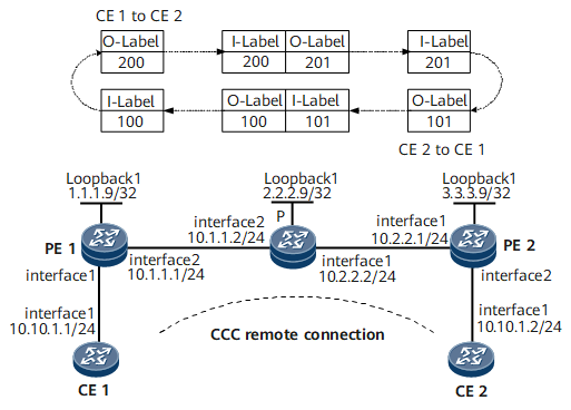
In this networking, CE1 and CE2 connect to different PEs. To allow the two CEs to communicate, create a remote CCC connection; configure two static CR-LSPs on the P to transmit packets in both directions.

Configuration Roadmap
The configuration roadmap is as follows:
Configure bidirectional static CR-LSPs to be used for the CCC connection only.
Enable MPLS L2VPN on the PEs only.
Configure two connections, one from CE1 to CE2, and the other from CE2 to CE1.
Data Preparation
To complete the configuration, you need the in-labels and out-labels of the remote CCC connections. Pay attention to the mapping between the in-labels and out-labels on the PEs and P. For details, see Figure 1.
Procedure
- Configure CEs.
# Configure CE1.
<HUAWEI> system-view
[~HUAWEI] sysname CE1
[*CE1] interface gigabitethernet 0/1/0
[*CE1-GigabitEthernet0/1/0] ip address 10.10.1.1 24
[*CE1-GigabitEthernet0/1/0] undo shutdown
[*CE1-GigabitEthernet0/1/0] quit
[*CE1] commit
# Configure CE2.
<HUAWEI> system-view
[~HUAWEI] sysname CE2
[*CE2] interface gigabitethernet 0/1/0
[*CE2-GigabitEthernet0/1/0] ip address 10.10.1.2 24
[*CE2-GigabitEthernet0/1/0] undo shutdown
[*CE2-GigabitEthernet0/1/0] quit
[*CE2] commit
- Assign an IP address to each interface on devices on the MPLS backbone network.
# Configure PE1.
<HUAWEI> system-view
[~HUAWEI] sysname PE1
[*PE1] interface loopback 1
[*PE1-LoopBack1] ip address 1.1.1.9 32
[*PE1-LoopBack1] quit
[*PE1] interface gigabitethernet 0/1/8
[*PE1-GigabitEthernet0/1/8] ip address 10.1.1.1 24
[*PE1-GigabitEthernet0/1/8] undo shutdown
[*PE1-GigabitEthernet0/1/8] quit
[*PE1] commit
# Configure P.
<HUAWEI> system-view
[~HUAWEI] sysname P
[*P] interface loopback 1
[*P-LoopBack1] ip address 2.2.2.9 32
[*P-LoopBack1] quit
[*P] interface gigabitethernet 0/1/0
[*P-GigabitEthernet0/1/0] ip address 10.2.2.2 24
[*P-GigabitEthernet0/1/0] undo shutdown
[*P-GigabitEthernet0/1/0] quit
[*P] interface gigabitethernet 0/1/8
[*P-GigabitEthernet0/1/8] ip address 10.1.1.2 24
[*P-GigabitEthernet0/1/8] undo shutdown
[*P-GigabitEthernet0/1/8] quit
[*P] commit
# Configure PE2.
<HUAWEI> system-view
[~HUAWEI] sysname PE2
[*PE2] interface loopback 1
[*PE2-LoopBack1] ip address 3.3.3.9 32
[*PE2-LoopBack1] quit
[PE2] interface gigabitethernet 0/1/0
[*PE2-GigabitEthernet0/1/0] ip address 10.2.2.1 24
[*PE2-GigabitEthernet0/1/0] undo shutdown
[*PE2-GigabitEthernet0/1/0] quit
[*PE2] commit
- Configure basic MPLS TE functions on an MPLS backbone network.
# Configure PE1.
[~PE1] mpls lsr-id 1.1.1.9
[*PE1] mpls
[*PE1-mpls] mpls te
[*PE1-mpls] quit
[*PE1] interface gigabitethernet 0/1/8
[*PE1-GigabitEthernet0/1/8] mpls
[*PE1-GigabitEthernet0/1/8] mpls te
[*PE1-GigabitEthernet0/1/8] quit
[*PE1] commit
# Configure P.
[~P] mpls lsr-id 2.2.2.9
[*P] mpls
[*P-mpls] mpls te
[*P-mpls] quit
[*P] interface gigabitethernet 0/1/0
[*P-GigabitEthernet0/1/0] mpls
[*P-GigabitEthernet0/1/0] mpls te
[*P-GigabitEthernet0/1/0] quit
[*P] interface gigabitethernet 0/1/8
[*P-GigabitEthernet0/1/8] mpls
[*P-GigabitEthernet0/1/8] mpls te
[*P-GigabitEthernet0/1/8] quit
[*P] commit
# Configure PE2.
[~PE2] mpls lsr-id 3.3.3.9
[*PE2] mpls
[*PE2-mpls] mpls te
[*PE2-mpls] quit
[*PE2] interface gigabitethernet 0/1/0
[*PE2-GigabitEthernet0/1/0] mpls
[*PE2-GigabitEthernet0/1/0] mpls te
[*PE2-GigabitEthernet0/1/0] quit
[*PE2] commit
- Configure static CR-LSPs on the P.
# Configure one static CR-LSP for transmitting PE1-PE2 packets and another one for transmitting PE2-PE1 packets.
[~P] static-cr-lsp transit PE1-PE2 incoming-interface gigabitethernet 0/1/8 in-label 200 nexthop 10.2.2.1 out-label 201
[*P] static-cr-lsp transit PE2-PE1 incoming-interface gigabitethernet 0/1/0 in-label 101 nexthop 10.1.1.1 out-label 100
[*P] commit
- Create remote CCC connections on the PEs.
# Configure PE1: enable MPLS L2VPN globally; create a CE1-CE2 remote CCC connection, with the inbound interface connecting to CE1, the outbound interface connecting to the P, in-label 100, and out-label 200.
[~PE1] mpls l2vpn
[*PE1-l2vpn] quit
[*PE1] interface gigabitethernet 0/1/0
[*PE1-GigabitEthernet0/1/0] undo shutdown
[*PE1-GigabitEthernet0/1/0] quit
[*PE1] ccc CE1-CE2 interface gigabitethernet 0/1/0 in-label 100 out-label 200 nexthop 10.1.1.2
# Configure PE2: enable MPLS L2VPN globally; create a CE2-CE1 remote CCC connection, with the inbound interface connecting to CE2, the outbound interface connecting to the P, in-label 201, and out-label 101.
[~PE2] mpls l2vpn
[*PE2-l2vpn] quit
[*PE2] interface gigabitethernet 0/1/8
[*PE2-GigabitEthernet0/1/8] undo shutdown
[*PE2-GigabitEthernet0/1/8] quit
[*PE2] ccc CE2-CE1 interface gigabitethernet 0/1/8 in-label 201 out-label 101 nexthop 10.2.2.2
[*PE2] commit
- Verify the configuration.
After the configuration is complete, check CCC information on the PEs. The command outputs show that a remote CCC connection has been established on PE1 and PE2 and both connections are in the Up state.
<~PE1> display vll ccc
total  ccc vc : 1
local  ccc vc : 0,  0 up
remote ccc vc : 1,  1 up

name: CE1-CE2, type: remote, state: up,
intf: GigabitEthernet0/1/0 (up), in-label: 100 , out-label: 200 , nexthop : 10.1.1.2
VC last up time : 2008-07-24 12:31:31
VC total up time: 0 days, 2 hours, 12 minutes, 51 seconds
<~PE2> display vll ccc
total  ccc vc : 1
local  ccc vc : 0,  0 up
remote ccc vc : 1,  1 up

name: CE2-CE1, type: remote, state: up,
intf: GigabitEthernet0/1/8 (up), in-label: 201 , out-label: 101 , nexthop : 10.2.2.2
VC last up time : 2008-07-24 12:31:31
VC total up time: 0 days, 2 hours, 12 minutes, 51 seconds
Run the display l2vpn ccc-interface vc-type ccc command on the PEs. The command output shows that the VC type is CCC and the VC status is Up. The following example uses the command output on PE1:
<~PE1> display l2vpn ccc-interface vc-type ccc
Total ccc-interface of CCC : 1
up (1), down (0)
Interface                     Encap Type               State     VC Type
GigabitEthernet0/1/0               ethernet                    up        ccc
Run the display mpls lsp command on the P. The command output shows the label and interface information of the two static CR-LSPs that have been established.
<~P> display mpls lsp
----------------------------------------------------------------------
                 LSP Information: STATIC LSP
----------------------------------------------------------------------
FEC                In/Out Label  In/Out IF                      Vrf Name
-/-                200/201       GE0/1/8/GE0/1/0
-/-                101/100       GE0/1/0/GE0/1/8
Run the ping command on the CEs. CE1 and CE2 can ping each other. The following example uses the command output on CE1:
<~CE1> ping 10.10.1.2
  PING 10.10.1.2: 56  data bytes, press CTRL_C to break
    Reply from 10.10.1.2: bytes=56 Sequence=1 ttl=255 time=58 ms
    Reply from 10.10.1.2: bytes=56 Sequence=2 ttl=255 time=67 ms
    Reply from 10.10.1.2: bytes=56 Sequence=3 ttl=255 time=52 ms
    Reply from 10.10.1.2: bytes=56 Sequence=4 ttl=255 time=69 ms
    Reply from 10.10.1.2: bytes=56 Sequence=5 ttl=255 time=92 ms
  --- 10.10.1.2 ping statistics ---
    5 packet(s) transmitted
    5 packet(s) received
    0.00% packet loss
    round-trip min/avg/max = 52/67/92 ms
Configuration Files
CE1 configuration file
#
sysname CE1
#
interface GigabitEthernet0/1/0
 undo shutdown
 ip address 10.10.1.1 255.255.255.0
#
return
PE1 configuration file
#
sysname PE1
#
mpls lsr-id 1.1.1.9
#
mpls
 mpls te
#
mpls l2vpn
#
interface GigabitEthernet0/1/0
 undo shutdown
#
interface GigabitEthernet0/1/8
 undo shutdown
 ip address 10.1.1.1 255.255.255.0
 mpls
 mpls te
#
interface LoopBack1
 ip address 1.1.1.9 255.255.255.255
#
ccc CE1-CE2 interface GigabitEthernet0/1/0 in-label 100 out-label 200 nexthop 10.1.1.2
#
return
P configuration file
#
sysname P
#
mpls lsr-id 2.2.2.9
#
mpls
 mpls te
#
interface GigabitEthernet0/1/0
 undo shutdown
 ip address 10.2.2.2 255.255.255.0
 mpls
 mpls te
#
interface GigabitEthernet0/1/8
 undo shutdown
 ip address 10.1.1.2 255.255.255.0
 mpls
 mpls te
#
interface LoopBack1
 ip address 2.2.2.9 255.255.255.255
#
static-cr-lsp transit PE1-PE2 incoming-interface GigabitEthernet0/1/8 in-label 200 nexthop 10.2.2.1 out-label 201
static-cr-lsp transit PE2-PE1 incoming-interface GigabitEthernet0/1/0 in-label 101 nexthop 10.1.1.1 out-label 100
#
return
PE2 configuration file
#
sysname PE2
#
mpls lsr-id 3.3.3.9
#
mpls
 mpls te
#
mpls l2vpn
#
interface GigabitEthernet0/1/0
 undo shutdown
 ip address 10.2.2.1 255.255.255.0
 mpls
 mpls te
#
interface GigabitEthernet0/1/8
 undo shutdown
#
interface LoopBack1
 ip address 3.3.3.9 255.255.255.255
#
ccc CE2-CE1 interface GigabitEthernet0/1/8 in-label 201 out-label 101 nexthop 10.2.2.2
#
return
CE2 configuration file
#
sysname CE2
#
interface GigabitEthernet0/1/0
 undo shutdown
 ip address 10.10.1.2 255.255.255.0
#
return