Example for Configuring Mutual Protection Between a CCC VC and an LDP VC (Single-Homing 2PE Scenario)
This section provides an example for configuring mutual protection between a CCC VC and an LDP VC. Specifying the master/backup status of PEs allows for mutual protection between a CCC VC and an LDP VC.
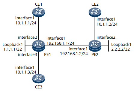
Networking Requirements
If CE1 fails or an AC fault occurs on CE1, CE3 cannot be authenticated. To resolve this problem, you can deploy CE2 as a backup for CE1. Under normal circumstances, CE3 accesses CE1 for authentication. If CE1 fails or an AC fault occurs on CE1, CE3 accesses CE2 for authentication to prevent a service interruption.

- Interfaces 1 through 3 in this example represent GE 0/1/0, GE0/1/2 and GE 0/1/1, respectively.
Configuration Roadmap
The configuration roadmap is as follows:
Configure a routing protocol on the backbone network to achieve connectivity between devices.
Configure basic MPLS functions on PEs.
Configure a CCC that allows CE1 and CE2 to communicate and a protection PW for the CCC on PE1.
Data Preparation
- Peer IP addresses and VLAN IDs
- Basic MPLS capabilities of peers
- CCC VC and LDP VC services on the peers
Procedure
- Configure CEs.
# Configure CE1.
<HUAWEI> system-view
[~HUAWEI] sysname CE1
[*CE1] interface gigabitethernet0/1/0.100
[*CE1-GigabitEthernet0/1/0.100] undo shutdown
[*CE1-GigabitEthernet0/1/0.100] vlan-type dot1q 100
[*CE1-GigabitEthernet0/1/0.100] ip address 10.1.1.1 255.255.255.0
[*CE1-GigabitEthernet0/1/0.100] quit
[*CE1] commit
# Configure CE2.
<HUAWEI> system-view
[~HUAWEI] sysname CE2
[*CE2] interface gigabitethernet0/1/0.100
[*CE2-GigabitEthernet0/1/0.100] undo shutdown
[*CE2-GigabitEthernet0/1/0.100] vlan-type dot1q 100
[*CE2-GigabitEthernet0/1/0.100] ip address 10.1.1.2 255.255.255.0
[*CE2-GigabitEthernet0/1/0.100] quit
[*CE2] commit
# Configure CE3.
<HUAWEI> system-view
[~HUAWEI] sysname CE3
[*CE3] interface gigabitethernet0/1/0.100
[*CE3-GigabitEthernet0/1/0.100] undo shutdown
[*CE3-GigabitEthernet0/1/0.100] vlan-type dot1q 100
[*CE3-GigabitEthernet0/1/0.100] ip address 10.1.1.3 255.255.255.0
[*CE3-GigabitEthernet0/1/0.100] quit
[*CE3] commit
- Assign an IP address to each interface on devices on the MPLS backbone network.
# Configure PE1.
<HUAWEI> system-view
[~HUAWEI] sysname PE1
[*PE1] interface loopback 1
[*PE1-LoopBack1] ip address 1.1.1.1 32
[*PE1-LoopBack1] quit
[*PE1] interface gigabitethernet0/1/0
[*PE1-GigabitEthernet0/1/0] undo shutdown
[*PE1-GigabitEthernet0/1/0] ip address 192.168.1.1 24
[*PE1-GigabitEthernet0/1/0] quit
[*PE1] commit
# Configure PE2.
<HUAWEI> system-view
[~HUAWEI] sysname PE2
[*PE2] interface loopback 1
[*PE2-LoopBack1] ip address 2.2.2.2 32
[*PE2-LoopBack1] quit
[*PE2] interface gigabitethernet0/1/0
[*PE2-GigabitEthernet0/1/0] undo shutdown
[*PE2-GigabitEthernet0/1/0] ip address 192.168.1.2 24
[*PE2-GigabitEthernet0/1/0] quit
[*PE2] commit
- Configure basic MPLS functions and establish LSPs between the PEs.
# Configure PE1.
[~PE1] mpls lsr-id 1.1.1.1
[*PE1] mpls
[*PE1-mpls] quit
[*PE1] mpls ldp
[*PE1-mpls-ldp] quit
[*PE1] interface gigabitethernet0/1/0
[*PE1-GigabitEthernet0/1/0] mpls
[*PE1-GigabitEthernet0/1/0] mpls ldp
[*PE1-GigabitEthernet0/1/0] quit
[*PE1] commit
# Configure PE2.
[~PE2] mpls lsr-id 2.2.2.2
[*PE2] mpls
[*PE2-mpls] quit
[*PE2] mpls ldp
[*PE2-mpls-ldp] quit
[*PE2] interface gigabitethernet0/1/0
[*PE2-GigabitEthernet0/1/0] mpls
[*PE2-GigabitEthernet0/1/0] mpls ldp
[*PE2-GigabitEthernet0/1/0] quit
[*PE2] commit
- Configure an IGP. In this example, OSPF is used.
# Configure PE1.
[~PE1] ospf 1
[*PE1-ospf-1] area 0.0.0.0
[*PE1-ospf-1-area-0.0.0.0] network 1.1.1.1 0.0.0.0
[*PE1-ospf-1-area-0.0.0.0] network 192.168.1.1 0.0.0.255
[*PE1-ospf-1-area-0.0.0.0] quit
[*PE1-ospf-1] quit
[*PE1] commit
# Configure PE2.
[~PE2] ospf 1
[*PE2-ospf-1] area 0.0.0.0
[*PE2-ospf-1-area-0.0.0.0] network 2.2.2.2 0.0.0.0
[*PE2-ospf-1-area-0.0.0.0] network 192.168.1.2 0.0.0.255
[*PE2-ospf-1-area-0.0.0.0] quit
[*PE2-ospf-1] quit
[*PE2] commit
- Enable MPLS L2VPN on each PE.
# Configure PE1.
[~PE1] mpls l2vpn
[*PE1-l2vpn] quit
[*PE1] commit
# Configure PE2.
[~PE2] mpls l2vpn
[*PE2-l2vpn] quit
[*PE2] commit
- Create a CCC VC and LDP VCs on the PEs.
# Configure PE1.
[~PE1] interface gigabitethernet0/1/2.100
[*PE1-GigabitEthernet0/1/2.100] vlan-type dot1q 100
[*PE1-GigabitEthernet0/1/2.100] mpls ccc out-interface gigabitethernet0/1/1.100
[*PE1-GigabitEthernet0/1/2.100] mpls l2vc 2.2.2.2 100 secondary
[*PE1-GigabitEthernet0/1/2.100] mpls l2vpn redundancy master
[*PE1-GigabitEthernet0/1/2.100] quit
[*PE1] interface gigabitethernet 0/1/1.100
[*PE1-GigabitEthernet0/1/1.100] vlan-type dot1q 100
[*PE1-GigabitEthernet0/1/1.100] mpls ccc out-interface gigabitethernet0/1/2.100
[*PE1-GigabitEthernet0/1/1.100] quit
[*PE1] commit
# Configure PE2.
[~PE2] interface gigabitethernet 0/1/1.100
[*PE2-GigabitEthernet0/1/1.100] vlan-type dot1q 100
[*PE2-GigabitEthernet0/1/1.100] mpls l2vc 1.1.1.1 100
[*PE2-GigabitEthernet0/1/1.100] quit
[*PE2] commit
- Verify the configuration.
After the configuration is complete, check CCC VC and LDP VC information on the PE1. The command outputs show that CCC VC and LDP VC connection has been established on PE1 and both connections are in the Up state.
<PE1> display mpls l2vpn vpws
Pri : Primary            Sec : Secondary            Byp : Bypass
PWb : PW-bypass          ACb : AC-bypass
Access Circuit                Virtual Circuit               States Active   Role
GE0/1/2.100                    GE0/1/1.100                 Up     Active   Pri
                               2.2.2.2:2                   Up     Inactive Sec
GE0/1/1.100                    GE0/1/2.100                 Up     Active   Pri
Configuration Files
CE1 configuration file
#
sysname CE1
#
interface GigabitEthernet0/1/0.100
 undo shutdown
 ip address 10.1.1.1 255.255.255.0
  vlan-type dot1q 100
#
return
CE2 configuration file
#
sysname CE2
#
interface GigabitEthernet0/1/0.100
 undo shutdown
 ip address 10.1.1.2 255.255.255.0
  vlan-type dot1q 100
#
return
CE3 configuration file
#
sysname CE3
#
interface GigabitEthernet0/1/0.100
 undo shutdown
 ip address 10.1.1.3 255.255.255.0
  vlan-type dot1q 100
#
return
PE1 configuration file
#
sysname PE1
#
mpls lsr-id 1.1.1.1
#
mpls
mpls ldp
#
mpls l2vpn
#
interface GigabitEthernet0/1/2.100
 undo shutdown
 vlan-type dot1q 100
 mpls ccc out-interface GigabitEthernet0/1/1.100
 mpls l2vc 2.2.2.2 100 secondary
 mpls l2vpn redundancy master
#
interface GigabitEthernet0/1/1.100
 vlan-type dot1q 100
 mpls ccc out-interface GigabitEthernet0/1/2.100
#
interface GigabitEthernet0/1/0
 undo shutdown
 ip address 192.168.1.1 255.255.255.0
 mpls
 mpls ldp
#
interface LoopBack1
 ip address 1.1.1.1 255.255.255.255
#
ospf 1
 area 0.0.0.0
  network 1.1.1.1 0.0.0.0
  network 192.168.1.1 0.0.0.255
#
return
PE2 configuration file
#
sysname PE2
#
mpls lsr-id 2.2.2.2
#
mpls
mpls ldp
#
mpls l2vpn
#
interface GigabitEthernet0/1/0
 undo shutdown
 ip address 192.168.1.2 255.255.255.0
 mpls
 mpls ldp
#
#interface GigabitEthernet0/1/1.100
 undo shutdown
 vlan-type dot1q 100
 mpls l2vc 1.1.1.1 100
#
interface LoopBack1
 ip address 2.2.2.2 255.255.255.255
#
ospf 1
 area 0.0.0.0
  network 2.2.2.2 0.0.0.0
  network 192.168.1.2 0.0.0.255
#
return