Example for Configuring E-PW APS for Static SS-PWs
In an E-PW APS scenario, MPLS OAM is used to detect the status of static SS-PWs.
Networking Requirements

This chapter applies only to the NetEngine 8000 F1A.
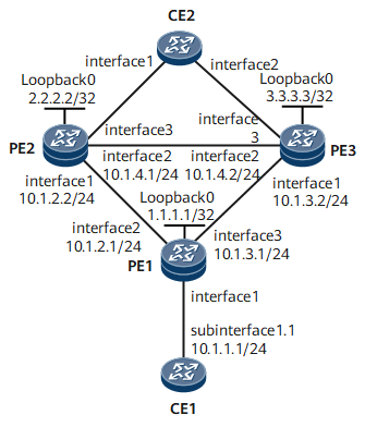
On the public network shown in Figure 1, three PEs belong to the same IGP domain, and static bidirectional co-routed LSPs must be deployed. In addition, CE1 and CE2 need to reliably communicate through the three PEs on the public network.
To meet this requirement, use E-PW APS for static PWs to ensure service reliability. As the three PEs belong to the same IGP domain, the PWs can be SS-PWs.
Configuration Roadmap
The configuration roadmap is as follows:
Configure interface IP addresses and a routing protocol.
Configure MPLS and public network tunnels.
In this example, static bidirectional co-routed LSPs are used between PE1 and PE2, between PE1 and PE3, and between PE2 and PE3. The specific configurations include:
Configure basic MPLS functions and enable MPLS TE.
Configure MPLS TE tunnel interfaces.
Configure the ingress and egress for each static bidirectional co-routed LSP.
Configure reverse tunnel binding on PE2 and PE3.
Configure a PW protection group (static PWs are used in this example), which includes:
Configure a primary PW between PE1 and PE2.
Configure a secondary PW between PE1 and PE3.
Configure a bypass PW between PE2 and PE3.
Configure E-PW APS, which includes:
Configure a PW APS instance on PE1.
Configure an E-PW APS instance on PE2 and PE3.
Bind PWs to PW APS instances.
Configure MPLS OAM to detect PW status.
Configure CEs to access the L2VPN through VLANs on the AC side.
Data Preparation
To complete the configuration, you need the following data:
PEs' interface numbers, IP addresses and OSPF process IDs
PEs' LSR IDs, tunnel interface numbers and IP addresses, incoming and outgoing tunnel labels, next hop address or outbound interface on the ingress of each static bidirectional co-routed LSP, and inbound interface on the egress of each static bidirectional co-routed LSP
Destination IP addresses, VC IDs, and VC types of L2VCs and transmit/receive labels of static PWs
APS instance numbers and the roles, local numbers, and remote numbers of the E-PW APS instances on PEs (the E-PW APS instance role is slave on PE2 and master on PE1).
Procedure
- Configure interface IP addresses and a routing protocol.
Configure the IP address and mask for each interface.
In this example, OSPF is used as the IGP for PE1, PE2, and PE3 to communicate at the network layer. The configuration details are not provided here.
- Configure MPLS and public network tunnels.
In this example, static bidirectional co-routed LSPs are used between PE1, PE2, and PE3.
- Configure the ingress and egress for each static bidirectional co-routed LSP.
A static bidirectional co-routed LSP can go up on the ingress only when the LSP name is the same as the tunnel interface name on the ingress. Note that the first letter of the tunnel interface name must be uppercase. The transit nodes and egress do not have this restriction.
# Configure PE1 as the ingress for the static bidirectional co-routed LSP from PE1 to PE2 and that from PE1 to PE3.
[~PE1] bidirectional static-cr-lsp ingress Tunnel10
[*PE1-bi-static-ingress-Tunnel10] forward outgoing-interface GigabitEthernet0/1/1 nexthop 10.1.2.2 out-label 20
[*PE1-bi-static-ingress-Tunnel10] backward in-label 30 lsrid 2.2.2.2 tunnel-id 100
[*PE1] bidirectional static-cr-lsp ingress Tunnel11
[*PE1-bi-static-ingress-Tunnel11] forward outgoing-interface GigabitEthernet0/1/2 nexthop 10.1.3.2 out-label 40
[*PE1-bi-static-ingress-Tunnel11] backward in-label 50 lsrid 3.3.3.3 tunnel-id 200
[*PE1-bi-static-ingress-Tunnel11] quit
[*PE1] commit
# Configure PE2 as the egress of the static bidirectional co-routed LSP from PE2 to PE1 and as the ingress of the static bidirectional co-routed LSP from PE2 to PE3.
[~PE2] bidirectional static-cr-lsp egress Tunnel10
[*PE2-bi-static-egress-Tunnel10] forward outgoing-interface GigabitEthernet0/1/0 in-label 20 lsrid 1.1.1.1 tunnel-id 100
[*PE2-bi-static-egress-Tunnel10] backward nexthop 10.1.2.1 out-label 30
[*PE2] bidirectional static-cr-lsp ingress Tunnel12
[*PE2-bi-static-ingress-Tunnel12] forward outgoing-interface GigabitEthernet0/1/1 nexthop 10.1.4.2 out-label 60
[*PE2-bi-static-ingress-Tunnel12] backward in-label 70 lsrid 3.3.3.3 tunnel-id 300
[*PE2-bi-static-ingress-Tunnel12] quit
[*PE2] commit
# Configure PE3 as the egress for the static bidirectional co-routed LSP from PE1 to PE3 and that from PE2 to PE3.
[~PE3] bidirectional static-cr-lsp egress Tunnel11
[*PE3-bi-static-egress-Tunnel11] forward outgoing-interface GigabitEthernet0/1/0 in-label 40 lsrid 1.1.1.1 tunnel-id 200
[*PE3-bi-static-egress-Tunnel11] backward nexthop 10.1.2.1 out-label 30
[*PE3-bi-static-egress-Tunnel11] quit
[*PE3] bidirectional static-cr-lsp egress Tunnel12
[*PE3-bi-static-egress-Tunnel12] forward outgoing-interface GigabitEthernet0/1/1 in-label 60 lsrid 2.2.2.2 tunnel-id 300
[*PE3-bi-static-egress-Tunnel12] backward nexthop 10.1.4.1 out-label 70
[*PE3-bi-static-egress-Tunnel12] quit
[*PE3] commit
- Configure the ingress and egress for each static bidirectional co-routed LSP.
- Configure a PW protection group.
Static PWs are used in this example.
When configuring a static PW, you must specify the VC ID. Otherwise, the PW cannot be bound to a PW APS instance.
# Configure the primary and secondary PWs on PE1.
[~PE1] mpls l2vpn
[*PE1-l2vpn] quit
[*PE1] tunnel-policy 1
[*PE1-tunnel-policy-1] tunnel binding destination 2.2.2.2 te Tunnel10
[*PE1-tunnel-policy-1] tunnel binding destination 3.3.3.3 te Tunnel11
[*PE1-tunnel-policy-1] quit
[*PE1] interface gigabitethernet 0/1/0
[*PE1-GigabitEthernet0/1/0] undo shutdown
[*PE1-GigabitEthernet0/1/0] quit
[*PE1] interface gigabitethernet 0/1/0.1
[*PE1-GigabitEthernet0/1/0.1] vlan-type dot1q 10
[*PE1-GigabitEthernet0/1/0.1] mpls static-l2vc destination 2.2.2.2 1 transmit-vpn-label 100 receive-vpn-label 200 tunnel-policy 1
[*PE1-GigabitEthernet0/1/0.1] mpls static-l2vc destination 3.3.3.3 2 transmit-vpn-label 300 receive-vpn-label 400 tunnel-policy 1 secondary
[*PE1-GigabitEthernet0/1/0.1] quit
[*PE1] commit
# Configure the primary and bypass PWs on PE2.
[~PE2] mpls l2vpn
[*PE2-l2vpn] quit
[*PE2] tunnel-policy 1
[*PE2-tunnel-policy-1] tunnel binding destination 1.1.1.1 te Tunnel10
[*PE2-tunnel-policy-1] tunnel binding destination 3.3.3.3 te Tunnel12
[*PE2-tunnel-policy-1] quit
[*PE2] interface eth-trunk 10
[*PE2-Eth-Trunk10] quit
[*PE2] interface eth-trunk 10.1
[*PE2-Eth-Trunk10.1] vlan-type dot1q 10
[*PE2-Eth-Trunk10.1] mpls static-l2vc destination 1.1.1.1 1 transmit-vpn-label 200 receive-vpn-label 100 tunnel-policy 1
[*PE2-Eth-Trunk10.1] mpls static-l2vc destination 3.3.3.3 3 transmit-vpn-label 500 receive-vpn-label 600 tunnel-policy 1 bypass
[*PE2-Eth-Trunk10.1] quit
[*PE2] commit
# Configure the primary and bypass PWs on PE3.
[~PE3] mpls l2vpn
[*PE3-l2vpn] quit
[*PE3] tunnel-policy 1
[*PE3-tunnel-policy-1] tunnel binding destination 1.1.1.1 te Tunnel11
[*PE3-tunnel-policy-1] tunnel binding destination 2.2.2.2 te Tunnel12
[*PE3-tunnel-policy-1] quit
[*PE3] interface eth-trunk 10
[*PE3-Eth-Trunk10] quit
[*PE3] interface eth-trunk 10.1
[*PE3-Eth-Trunk10.1] vlan-type dot1q 10
[*PE3-Eth-Trunk10.1] mpls static-l2vc destination 1.1.1.1 2 transmit-vpn-label 400 receive-vpn-label 300 tunnel-policy 1
[*PE3-Eth-Trunk10.1] mpls static-l2vc destination 2.2.2.2 3 transmit-vpn-label 600 receive-vpn-label 500 tunnel-policy 1 bypass
[*PE3-Eth-Trunk10.1] quit
[*PE3] commit
- Configure E-PW APS.
- Configure MPLS OAM to detect PW status.
# Configure PE1.
[~PE1] mpls
[*PE1-mpls] mpls oam
[*PE1-mpls] quit
[*PE1] mpls-oam
[*PE1-mpls-oam] mpls oam l2vc peer-ip 2.2.2.2 vc-id 1 vc-type vlan type cv
[*PE1-mpls-oam] mpls oam l2vc peer-ip 3.3.3.3 vc-id 2 vc-type vlan type cv
[*PE1-mpls-oam] mpls oam l2vc enable send peer-ip 2.2.2.2 vc-id 1 vc-type vlan
[*PE1-mpls-oam] mpls oam l2vc enable receive peer-ip 3.3.3.3 vc-id 2 vc-type vlan
[*PE1-mpls-oam] mpls oam l2vc enable receive peer-ip 2.2.2.2 vc-id 1 vc-type vlan
[*PE1-mpls-oam] mpls oam l2vc enable send peer-ip 3.3.3.3 vc-id 2 vc-type vlan
[*PE1-mpls-oam] quit
[*PE1] commit
# Configure PE2.
[~PE2] mpls
[*PE2-mpls] mpls oam
[*PE2-mpls] quit
[*PE2] mpls-oam
[*PE2-mpls-oam] mpls oam l2vc peer-ip 1.1.1.1 vc-id 1 vc-type vlan type cv
[*PE2-mpls-oam] mpls oam l2vc peer-ip 3.3.3.3 vc-id 3 vc-type vlan type cv
[*PE2-mpls-oam] mpls oam l2vc enable receive peer-ip 1.1.1.1 vc-id 1 vc-type vlan
[*PE2-mpls-oam] mpls oam l2vc enable send peer-ip 1.1.1.1 vc-id 1 vc-type vlan
[*PE2-mpls-oam] mpls oam l2vc enable receive peer-ip 3.3.3.3 vc-id 3 vc-type vlan
[*PE2-mpls-oam] mpls oam l2vc enable send peer-ip 3.3.3.3 vc-id 3 vc-type vlan
[*PE2-mpls-oam] quit
[*PE2] commit
# Configure PE3.
[~PE3] mpls
[*PE3-mpls] mpls oam
[*PE3-mpls] quit
[*PE3] mpls-oam
[*PE3-mpls-oam] mpls oam l2vc peer-ip 1.1.1.1 vc-id 2 vc-type vlan type cv
[*PE3-mpls-oam] mpls oam l2vc peer-ip 2.2.2.2 vc-id 3 vc-type vlan type cv
[*PE3-mpls-oam] mpls oam l2vc enable receive apeer-ip 1.1.1.1 vc-id 2 vc-type vlan
[*PE3-mpls-oam] mpls oam l2vc enable send peer-ip 1.1.1.1 vc-id 2 vc-type vlan
[*PE3-mpls-oam] mpls oam l2vc enable receive peer-ip 2.2.2.2 vc-id 3 vc-type vlan
[*PE3-mpls-oam] mpls oam l2vc enable send peer-ip 2.2.2.2 vc-id 3 vc-type vlan
[*PE3-mpls-oam] quit
[*PE3] commit
Check MPLS OAM information on PE1.
[~PE1] display mpls oam l2vc all -------------------------------------------------------------------------------- Total Oam Num: 2 Total Start Oam Num: 2 Total Defect Oam Num: 0 -------------------------------------------------------------------------------- No. Peer IP VC Type VC ID Status -------------------------------------------------------------------------------- 1 2.2.2.2 vlan 1 Start/Non-defect 2 3.3.3.3 vlan 2 Start/Non-defect - Configure dual-homing protection on the AC side.
- Verify the configuration.
Ping the IP address of the VLANIF interface on CE2 from CE1.
# Configure CE2.
[~CE2]interface Vlanif 10
[*CE2-Vlanif100/1/0] ip address 10.1.1.2 24
[*CE2-Vlanif100/1/0] quit
[*CE2] commit
# Perform the ping operation.
[~CE1] ping 10.1.1.2
PING 10.1.1.2: 56  data bytes, press CTRL_C to break
    Reply from 10.1.1.2: bytes=56 Sequence=1 ttl=255 time=40 ms
    Reply from 10.1.1.2: bytes=56 Sequence=2 ttl=255 time=30 ms
    Reply from 10.1.1.2: bytes=56 Sequence=3 ttl=255 time=40 ms
    Reply from 10.1.1.2: bytes=56 Sequence=4 ttl=255 time=1 ms
    Reply from 10.1.1.2: bytes=56 Sequence=5 ttl=255 time=1 ms

  --- 10.1.1.2 ping statistics ---
    5 packet(s) transmitted
    5 packet(s) received
    0.00% packet loss
    round-trip min/avg/max = 1/22/40 ms
Configuration Files
CE1 configuration file
#
sysname CE1
#
interface GigabitEthernet0/1/0
 undo shutdown
#
interface GigabitEthernet0/1/0.1
 vlan-type dot1q 10
 ip address 10.1.1.1 255.255.255.0
#
return
PE1 configuration file
#
sysname PE1
#
mpls lsr-id 1.1.1.1
mpls
 mpls te
#
mpls l2vpn
#
pw-aps 1
#
bidirectional static-cr-lsp ingress Tunnel10
 forward outgoing-interface GigabitEthernet0/1/1 nexthop 10.1.2.2 out-label 20
 backward in-label 30 lsrid 2.2.2.2 tunnel-id 100
#
bidirectional static-cr-lsp ingress Tunnel11
 forward outgoing-interface GigabitEthernet0/1/2 nexthop 10.1.3.2 out-label 40
 backward in-label 50 lsrid 3.3.3.3 tunnel-id 200
#
mpls ldp
#
mpls ldp remote-peer 2.2.2.2
 remote-ip 2.2.2.2
#
mpls ldp remote-peer 3.3.3.3
 remote-ip 3.3.3.3
#
interface GigabitEthernet0/1/0
 undo shutdown
#
interface GigabitEthernet0/1/0.1
 vlan-type dot1q 10
 mpls static-l2vc destination 2.2.2.2 1 transmit-vpn-label 100 receive-vpn-label
 200 tunnel-policy 1
 mpls static-l2vc destination 3.3.3.3 2 transmit-vpn-label 300 receive-vpn-label
 400 tunnel-policy 1 secondary
 mpls l2vpn pw-aps 1 admin
#
interface GigabitEthernet0/1/1
 undo shutdown
 ip address 10.1.2.1 255.255.255.0
 mpls
 mpls te
#
interface GigabitEthernet0/1/2
 undo shutdown
 ip address 10.1.3.1 255.255.255.0
 mpls
 mpls te
#
interface LoopBack0
 ip address 1.1.1.1 255.255.255.255
#
interface Tunnel10
 ip address unnumbered interface LoopBack0
 tunnel-protocol mpls te
 destination 2.2.2.2
 mpls te signal-protocol cr-static
 mpls te tunnel-id 100
 mpls te bidirectional
 mpls te reserved-for-binding
#
interface Tunnel11
 ip address unnumbered interface LoopBack0
 tunnel-protocol mpls te
 destination 3.3.3.3
 mpls te signal-protocol cr-static
 mpls te tunnel-id 200
 mpls te bidirectional
 mpls te reserved-for-binding
#
ospf 1
 area 0.0.0.0
  network 10.1.2.0 0.0.0.255
  network 1.1.1.1 0.0.0.0
  network 10.1.3.0 0.0.0.255
#
tunnel-policy policy1
 tunnel binding destination 2.2.2.2 te Tunnel10
 tunnel binding destination 3.3.3.3 te Tunnel11
#
mpls-oam
 mpls oam l2vc peer-ip 2.2.2.2 vc-id 1 vc-type vlan type cv
 mpls oam l2vc peer-ip 3.3.3.3 vc-id 2 vc-type vlan type cv
 mpls oam l2vc enable receive peer-ip 2.2.2.2 vc-id 1 vc-type vlan
 mpls oam l2vc enable send peer-ip 2.2.2.2 vc-id 1 vc-type vlan
 mpls oam l2vc enable receive peer-ip 3.3.3.3 vc-id 2 vc-type vlan
 mpls oam l2vc enable send peer-ip 3.3.3.3 vc-id 2 vc-type vlan
#
return
PE2 configuration file
#
sysname PE2
#
lacp e-trunk system-id 00e0-fc00-0000
lacp e-trunk priority 100
#
mpls lsr-id 2.2.2.2
mpls
 mpls te
#
mpls l2vpn
#
pw-aps 2
 role slave
 remote-aps 3
#
bidirectional static-cr-lsp egress Tunnel10
 forward nexthop 10.1.4.2 out-label 60
 backward in-label 70
#
bidirectional static-cr-lsp egress Tunnel10
 forward outgoing-interface GigabitEthernet0/1/1 nexthop 10.1.4.2 out-label 60
 backward in-label 70 lsrid 3.3.3.3 tunnel-id 300
#
mpls ldp
#
mpls ldp remote-peer 1.1.1.1
 remote-ip 1.1.1.1
#
mpls ldp remote-peer 3.3.3.3
 remote-ip 3.3.3.3
#
e-trunk 10
 priority 10
 peer-address 3.3.3.3 source-address 2.2.2.2
#
interface Eth-Trunk10
 mode lacp-static
 e-trunk 10
#
interface Eth-Trunk10.1
 vlan-type dot1q 10
 mpls static-l2vc destination 1.1.1.1 1 transmit-vpn-label 200 receive-vpn-label
 100 tunnel-policy 1
 mpls static-l2vc destination 3.3.3.3 3 transmit-vpn-label 500 receive-vpn-label
 600 tunnel-policy 1 bypass
 mpls l2vpn pw-aps 2 admin
#
interface GigabitEthernet0/1/0
 undo shutdown
 ip address 10.1.2.2 255.255.255.0
 mpls
 mpls te
#
interface GigabitEthernet0/1/1
 undo shutdown
 ip address 10.1.4.1 255.255.255.0
 mpls
 mpls te
#
interface GigabitEthernet0/1/2
 undo shutdown
 eth-trunk 10
#
interface LoopBack0
 ip address 2.2.2.2 255.255.255.255
#
interface Tunnel10
 ip address unnumbered interface LoopBack0
 tunnel-protocol mpls te
 destination 1.1.1.1
 mpls te signal-protocol cr-static
 mpls te tunnel-id 100
 mpls te passive-tunnel
 mpls te binding bidirectional static-cr-lsp egress Tunnel10
 mpls te reserved-for-binding
#
interface Tunnel12
 ip address unnumbered interface LoopBack0
 tunnel-protocol mpls te
 destination 3.3.3.3
 mpls te signal-protocol cr-static
 mpls te tunnel-id 300
 mpls te bidirectional
 mpls te reserved-for-binding
#
ospf 1
 area 0.0.0.0
  network 2.2.2.2 0.0.0.0
  network 10.1.4.0 0.0.0.255
  network 10.1.2.0 0.0.0.255
#
tunnel-policy policy1
 tunnel binding destination 1.1.1.1 te Tunnel10
 tunnel binding destination 3.3.3.3 te Tunnel12
#
mpls-oam
 mpls oam l2vc peer-ip 1.1.1.1 vc-id 1 vc-type vlan type cv
 mpls oam l2vc peer-ip 3.3.3.3 vc-id 3 vc-type vlan type cv
 mpls oam l2vc enable receive peer-ip 1.1.1.1 vc-id 1 vc-type vlan
 mpls oam l2vc enable send peer-ip 1.1.1.1 vc-id 1 vc-type vlan
 mpls oam l2vc enable receive peer-ip 3.3.3.3 vc-id 3 vc-type vlan
 mpls oam l2vc enable send peer-ip 3.3.3.3 vc-id 3 vc-type vlan
#
return
PE3 configuration file
#
sysname PE3
#
lacp e-trunk system-id 00e0-fc00-0000
lacp e-trunk priority 100
#
mpls lsr-id 3.3.3.3
mpls
 mpls te
#
mpls l2vpn
#
pw-aps 3
 role master
 remote-aps 2
#
bidirectional static-cr-lsp egress Tunnel11
 forward outgoing-interface GigabitEthernet0/1/0 in-label 40 lsrid 1.1.1.1 tunnel-id 200
 backward nexthop 10.1.2.1 out-label 30
#
bidirectional static-cr-lsp egress Tunnel12
 forward outgoing-interface GigabitEthernet0/1/1 in-label 60 lsrid 2.2.2.2 tunnel-id 300
 backward nexthop 10.1.4.1 out-label 70
#
mpls ldp
#
mpls ldp remote-peer 1.1.1.1
 remote-ip 1.1.1.1
#
mpls ldp remote-peer 2.2.2.2
 remote-ip 2.2.2.2
#
e-trunk 10
 priority 20
 peer-address 2.2.2.2 source-address 3.3.3.3
#
interface Eth-Trunk10
 mode lacp-static
 e-trunk 10
#
interface Eth-Trunk10.1
 vlan-type dot1q 10
 mpls static-l2vc destination 1.1.1.1 2 transmit-vpn-label 400 receive-vpn-label
 300 tunnel-policy 1
 mpls static-l2vc destination 2.2.2.2 3 transmit-vpn-label 600 receive-vpn-label
 500 tunnel-policy 1 bypass
 mpls l2vpn pw-aps 3 admin
#
interface GigabitEthernet0/1/0
 undo shutdown
 ip address 10.1.3.2 255.255.255.0
 mpls
 mpls te
#
interface GigabitEthernet0/1/1
 undo shutdown
 ip address 10.1.4.2 255.255.255.0
 mpls
 mpls te
#
interface GigabitEthernet0/1/2
 undo shutdown
 eth-trunk 10
#
interface LoopBack0
 ip address 3.3.3.3 255.255.255.255
#
interface Tunnel11
 ip address unnumbered interface LoopBack0
 tunnel-protocol mpls te
 destination 1.1.1.1
 mpls te signal-protocol cr-static
 mpls te tunnel-id 200
 mpls te passive-tunnel
 mpls te binding bidirectional static-cr-lsp egress Tunnel11
 mpls te reserved-for-binding
#
interface Tunnel12
 ip address unnumbered interface LoopBack0
 tunnel-protocol mpls te
 destination 2.2.2.2
 mpls te signal-protocol cr-static
 mpls te tunnel-id 300
 mpls te passive-tunnel
 mpls te binding bidirectional static-cr-lsp egress Tunnel12
 mpls te reserved-for-binding
#
ospf 1
 area 0.0.0.0
  network 3.3.3.3 0.0.0.0
  network 10.1.3.0 0.0.0.255
  network 10.1.4.0 0.0.0.255
#
static-cr-lsp egress 1to2 incoming-interface GigabitEthernet0/1/1 in-label 20
#
tunnel-policy policy1
 tunnel binding destination 1.1.1.1 te Tunnel11
 tunnel binding destination 2.2.2.2 te Tunnel12
#
mpls-oam
 mpls oam l2vc peer-ip 1.1.1.1 vc-id 2 vc-type vlan type cv
 mpls oam l2vc peer-ip 2.2.2.2 vc-id 3 vc-type vlan type cv
 mpls oam l2vc enable receive peer-ip 1.1.1.1 vc-id 2 vc-type vlan
 mpls oam l2vc enable send peer-ip 1.1.1.1 vc-id 2 vc-type vlan
 mpls oam l2vc enable receive peer-ip 2.2.2.2 vc-id 3 vc-type vlan
 mpls oam l2vc enable send peer-ip 2.2.2.2 vc-id 3 vc-type vlan
#
return
CE2 configuration file
#
sysname CE2
#
interface Vlanif100/1/0
 ip address 10.1.1.2 255.255.255.0
#
interface Eth-Trunk10
 portswitch
 port trunk allow-pass vlan 10
 mode lacp-static
 trunkport gigabitethernet 0/1/0 to 0/1/1
#
interface GigabitEthernet0/1/0
 undo shutdown
 eth-trunk 10
#
interface GigabitEthernet0/1/1
 undo shutdown
 eth-trunk 10
#
return