Example for Configuring Static PW FRR
In static PW FRR scenarios with static MS-PWs, configuring dynamic BFD for PW helps facilitate traffic switching between primary and secondary PWs.
Networking Requirements
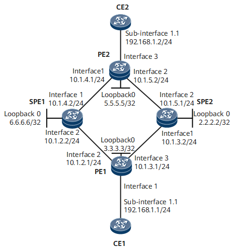
On the public network shown in Figure 1, dynamically associated bidirectional LSPs need to be established between PEs. CE1 and CE2 need to reliably communicate through the PEs and SPEs.
PW redundancy needs to be deployed on PE1 and PE2. For a pair of primary and secondary PWs that share the same source and destination and traverse dynamically associated bidirectional LSPs, you can configure static PW FRR to enhance network reliability. Because the PEs and SPEs belong to different IGP domains, multi-segment pseudo wires (MS-PWs) are required.
Configuration Roadmap
The configuration roadmap is as follows:
Assign an IP address to each interface and configure a routing protocol.
Configure basic MPLS functions and public network tunnels.
Configure a PW protection group, which includes:
Configure VPN-tunnel binding.
Configure a pair of primary and secondary static PWs on PE1 and PE2 and PW switching on SPE1 and SPE2.
Configure BFD for PW.
Configure a revertive switching policy.
Data Preparation
To complete the configuration, you need the following data:
Interface numbers and IP addresses of CE1, CE2, PE1, PE2, SPE1, and SPE2 (see Figure 1)
- OSPF process IDs (1) of PE1, PE2, SPE1, and SPE2
LSR IDs of PE1, PE2, SPE1, and SPE2
Local and remote IP addresses, VC IDs, and VC types of PWs
Procedure
- Assign an IP address to each interface. For configuration details, see Configuration Files in this section.
- Configure a routing protocol on each PE and SPE. For configuration details, see Configuration Files in this section.
- Configure basic MPLS functions and public network tunnels.
- Configure a static PW protection group.
- Configure static PWs.

In static PW FRR scenarios, if you do not configure the primary and secondary PWs to both receive packets, severe packet loss or service interruption may occur after a traffic switchover.
# Configure the primary and secondary static PWs on PE1.
[~PE1] mpls l2vpn
[*PE1-l2vpn] quit
[*PE1] interface GigabitEthernet0/1/0.1
[*PE1-GigabitEthernet0/1/0.1] vlan-type dot1q 1
[*PE1-GigabitEthernet0/1/0.1] mpls static-l2vc destination 6.6.6.6 1 transmit-vpn-label 1001 receive-vpn-label 1001 tunnel-policy bind control-word
[*PE1-GigabitEthernet0/1/0.1] mpls static-l2vc destination 2.2.2.2 3 transmit-vpn-label 1003 receive-vpn-label 1003 tunnel-policy bind control-word secondary
[*PE1-GigabitEthernet0/1/0.1] mpls l2vpn stream-dual-receiving
[*PE1-GigabitEthernet0/1/0.1] quit
[*PE1] commit
# Configure the primary and secondary static PWs on PE2.
[~PE2] mpls l2vpn
[*PE2-l2vpn] quit
[*PE2] interface GigabitEthernet0/1/2.1
[*PE2-GigabitEthernet0/1/2.1] vlan-type dot1q 1
[*PE2-GigabitEthernet0/1/2.1] mpls static-l2vc destination 6.6.6.6 2 transmit-vpn-label 1002 receive-vpn-label 1002 tunnel-policy bind control-word
[*PE2-GigabitEthernet0/1/2.1] mpls static-l2vc destination 2.2.2.2 4 transmit-vpn-label 1004 receive-vpn-label 1004 tunnel-policy bind control-word secondary
[*PE2-GigabitEthernet0/1/2.1] mpls l2vpn stream-dual-receiving
[*PE2-GigabitEthernet0/1/2.1] quit
[*PE2] commit
# Configure PW switching on SPE1.
[~SPE1] mpls l2vpn
[*SPE1-l2vpn] quit
[*SPE1] mpls switch-l2vc 3.3.3.3 1 trans 1001 recv 1001 tunnel-policy bind between 5.5.5.5 2 trans 1002 recv 1002 tunnel-policy bind encapsulation vlan control-word
[*SPE1] commit
# Configure PW switching on SPE2.
[~SPE2] mpls l2vpn
[*SPE2-l2vpn] quit
[*SPE2] mpls switch-l2vc 3.3.3.3 3 trans 1003 recv 1003 tunnel-policy bind between 5.5.5.5 4 trans 1004 recv 1004 tunnel-policy bind encapsulation vlan control-word
[*SPE2] commit
- Configure static PWs.
- Configure BFD for PW.
# Configure PE1.
[~PE1] bfd
[*PE1-bfd] quit
[*PE1] interface GigabitEthernet0/1/0.1
[*PE1-GigabitEthernet0/1/0.1] mpls l2vpn pw bfd remote-vcid 2
[*PE1-GigabitEthernet0/1/0.1] mpls l2vpn pw bfd remote-vcid 4 secondary
[*PE1-GigabitEthernet0/1/0.1] quit
[*PE1] commit
# Configure PE2.
[~PE2] bfd
[*PE2-bfd] quit
[*PE2] interface GigabitEthernet0/1/2.1
[*PE2-GigabitEthernet0/1/2.1] mpls l2vpn pw bfd remote-vcid 1
[*PE2-GigabitEthernet0/1/2.1] mpls l2vpn pw bfd remote-vcid 3 secondary
[*PE2-GigabitEthernet0/1/2.1] quit
[*PE2] commit
- Configure a revertive switching policy.
# Configure PE1.
[~PE1] interface GigabitEthernet0/1/0.1
[*PE1-GigabitEthernet0/1/0.1] mpls l2vpn reroute delay 40
[*PE1-GigabitEthernet0/1/0.1] quit
[*PE1] commit
# Configure PE2.
[~PE2] interface GigabitEthernet0/1/2.1
[*PE2-GigabitEthernet0/1/2.1] mpls l2vpn reroute delay 40
[*PE2-GigabitEthernet0/1/2.1] quit
[*PE2] commit
- Verify the configuration.
After the configurations are complete, the PW status on each PE and SPE is Up. The following example uses the command output on PE1.
[~PE1] display mpls static-l2vc interface gigabitethernet0/1/0.1
 *Client Interface     : GigabitEthernet0/1/0.1 is up
  AC Status            : up
  VC State             : up
  VC ID                : 1
  VC Type              : VLAN
  Destination          : 6.6.6.6
  Transmit VC Label    : 1001
  Receive VC Label     : 1001
  Label Status         : 0
  Token Status         : 0
  Control Word         : Enable
  VCCV Capabilty       : cw alert ttl lsp-ping bfd
  active state         : active
  OAM Protocol         : --
  OAM Status           : --
  OAM Fault Type       : --
  PW APS ID            : --
  PW APS Status        : --
  TTL Value            : 1
  Link State           : up
  Tunnel Policy        : bind
  PW Template Name     : --
  Main or Secondary    : Main
  load balance type    : flow
  Access-port          : false
  VC tunnel info       : 1 tunnels
  NO.0  TNL Type       : te    , TNL ID : 0x000000000300000001
  Create time          : 0 days, 0 hours, 41 minutes, 49 seconds
  UP time              : 0 days, 0 hours, 40 minutes, 12 seconds
  Last change time     : 0 days, 0 hours, 40 minutes, 12 seconds
  VC last up time      : 2015/08/04 07:35:02
  VC total up time     : 0 days, 0 hours, 40 minutes, 12 seconds
  CKey                 : 1
  NKey                 : 3506438260
  Dynamic BFD for PW   : enable
  Detect Multipier     : 3
  Min Transit Interval : 10
  Min Receive Interval : 10
  Dynamic BFD Session  : built
  BFD for PW           : available
    BFD sessionIndex   : --             BFD state : up

 *Client Interface     : GigabitEthernet0/1/0.1 is up
  AC Status            : up
  VC State             : up
  VC ID                : 3
  VC Type              : VLAN
  Destination          : 2.2.2.2
  Transmit VC Label    : 1003
  Receive VC Label     : 1003
  Label Status         : 0
  Token Status         : 0
  Control Word         : Enable
  VCCV Capabilty       : cw alert ttl lsp-ping bfd
  active state         : inactive
  OAM Protocol         : --
  OAM Status           : --
  OAM Fault Type       : --
  PW APS ID            : --
  PW APS Status        : --
  TTL Value            : 1
  Link State           : up
  Tunnel Policy        : bind
  PW Template Name     : --
  Main or Secondary    : Secondary
  load balance type    : flow
  Access-port          : false
  VC tunnel info       : 1 tunnels
  NO.0  TNL Type       : te    , TNL ID : 0x000000000300000002
  Create time          : 0 days, 0 hours, 41 minutes, 49 seconds
  UP time              : 0 days, 0 hours, 40 minutes, 31 seconds
  Last change time     : 0 days, 0 hours, 40 minutes, 31 seconds
  VC last up time      : 2015/08/04 07:34:43
  VC total up time     : 0 days, 0 hours, 40 minutes, 31 seconds
  CKey                 : 2
  NKey                 : 3506438259
  Dynamic BFD for PW   : enable
  Detect Multipier     : 3
  Min Transit Interval : 10
  Min Receive Interval : 10
  Dynamic BFD Session  : built
  BFD for PW           : available
    BFD sessionIndex   : --             BFD state : up

 Reroute policy        : delay 40 seconds
 Reason of last reroute: --
 Time of last reroute  : -- days, -- hours, -- minutes, -- seconds
 Delay timer ID        : --           Residual time :--
CE1 and CE2 can ping each other. The following example uses the command output on CE1.
[~CE1] ping 192.168.1.2
  PING 192.168.1.2: 56  data bytes, press CTRL_C to break
    Reply from 192.168.1.2: bytes=56 Sequence=1 ttl=255 time=55 ms
    Reply from 192.168.1.2: bytes=56 Sequence=2 ttl=255 time=1 ms
    Reply from 192.168.1.2: bytes=56 Sequence=3 ttl=255 time=1 ms
    Reply from 192.168.1.2: bytes=56 Sequence=4 ttl=255 time=1 ms
    Reply from 192.168.1.2: bytes=56 Sequence=5 ttl=255 time=1 ms

  --- 192.168.1.2 ping statistics ---
    5 packet(s) transmitted
    5 packet(s) received
    0.00% packet loss
    round-trip min/avg/max = 1/11/55 ms
Configuration Files
CE1 configuration file
#
sysname CE1
#
interface GigabitEthernet0/1/0
 undo shutdown
#
interface GigabitEthernet0/1/0.1
 vlan-type dot1q 1
 ip address 192.168.1.1 255.255.255.0
#
return
PE1 configuration file
#
sysname PE1
#
bfd
#
mpls lsr-id 3.3.3.3
#
mpls
 mpls te
 mpls rsvp-te
 mpls rsvp-te hello
 mpls te cspf
#
mpls l2vpn
#
explicit-path PE1toSPE1
 next hop 10.1.2.2
 next hop 6.6.6.6
#
explicit-path PE1toSPE2
 next hop 10.1.3.2
 next hop 2.2.2.2
#
interface GigabitEthernet0/1/0
 undo shutdown
#
interface GigabitEthernet0/1/0.1
 vlan-type dot1q 1
 mpls static-l2vc destination 6.6.6.6 1 transmit-vpn-label 1001 receive-vpn-label 1001 tunnel-policy bind control-word
 mpls l2vpn pw bfd remote-vcid 2
 mpls static-l2vc destination 2.2.2.2 3 transmit-vpn-label 1003 receive-vpn-label 1003 tunnel-policy bind control-word secondary
 mpls l2vpn pw bfd remote-vcid 4 secondary
 mpls l2vpn reroute delay 40
 mpls l2vpn stream-dual-receiving
#
interface GigabitEthernet0/1/1
 undo shutdown
 ip address 10.1.2.1 255.255.255.0
 mpls
 mpls te
 mpls rsvp-te
 mpls rsvp-te hello
#
interface GigabitEthernet0/1/2
 undo shutdown
 ip address 10.1.3.1 255.255.255.0
 mpls
 mpls te
 mpls rsvp-te
 mpls rsvp-te hello
 #
interface LoopBack0
 ip address 3.3.3.3 255.255.255.255
#
interface Tunnel11
 ip address unnumbered interface LoopBack0
 tunnel-protocol mpls te
 destination 6.6.6.6
 mpls te reserved-for-binding
 mpls te tunnel-id 1
 mpls te path explicit-path PE1toSPE1
#
interface Tunnel13
 ip address unnumbered interface LoopBack0
 tunnel-protocol mpls te
 destination 2.2.2.2
 mpls te reserved-for-binding
 mpls te tunnel-id 3
 mpls te path explicit-path PE1toSPE2
#
ospf 1
 opaque-capability enable
 graceful-restart
 area 0.0.0.0
  network 3.3.3.3 0.0.0.0
  network 10.1.2.0 0.0.0.255
  network 10.1.3.0 0.0.0.255
  mpls-te enable
#
tunnel-policy bind
 tunnel binding destination 2.2.2.2 te Tunnel13
 tunnel binding destination 6.6.6.6 te Tunnel11
#
return
SPE1 configuration file
#
sysname SPE1
#
mpls lsr-id 6.6.6.6
#
mpls
 mpls te
 mpls rsvp-te
 mpls rsvp-te hello
 mpls te cspf
#
mpls l2vpn
#
mpls switch-l2vc 3.3.3.3 1 trans 1001 recv 1001 tunnel-policy bind between 5.5.5.5 2 trans 1002 recv 1002 tunnel-policy bind encapsulation vlan control-word
#
explicit-path SPE1toPE1
 next hop 10.1.2.1
 next hop 3.3.3.3
#
explicit-path SPE1toPE2
 next hop 10.1.4.1
 next hop 5.5.5.5
#
interface GigabitEthernet0/1/0
 undo shutdown
 ip address 10.1.4.2 255.255.255.0
 mpls
 mpls te
 mpls rsvp-te
 mpls rsvp-te hello
#
interface GigabitEthernet0/1/1
 undo shutdown
 ip address 10.1.2.2 255.255.255.0
 mpls
 mpls te
 mpls rsvp-te
 mpls rsvp-te hello
#
interface LoopBack0
 ip address 6.6.6.6 255.255.255.255
#
interface Tunnel11
 ip address unnumbered interface LoopBack0
 tunnel-protocol mpls te
 destination 3.3.3.3
 mpls te reserved-for-binding
 mpls te tunnel-id 1
 mpls te path explicit-path SPE1toPE1
#
interface Tunnel12
 ip address unnumbered interface LoopBack0
 tunnel-protocol mpls te
 destination 5.5.5.5
 mpls te reserved-for-binding
 mpls te tunnel-id 2
 mpls te path explicit-path SPE1toPE2
#
ospf 1
 opaque-capability enable
 graceful-restart
 area 0.0.0.0
  network 6.6.6.6 0.0.0.0
  network 10.1.2.0 0.0.0.255
  network 10.1.4.0 0.0.0.255
  mpls-te enable
#
tunnel-policy bind
 tunnel binding destination 3.3.3.3 te Tunnel11
 tunnel binding destination 5.5.5.5 te Tunnel12
#
return
SPE2 configuration file
#
sysname SPE2
#
mpls lsr-id 2.2.2.2
#
mpls
 mpls te
 mpls rsvp-te
 mpls rsvp-te hello
 mpls te cspf
#
mpls l2vpn
#
mpls switch-l2vc 3.3.3.3 3 trans 1003 recv 1003 tunnel-policy bind between 5.5.5.5 4 trans 1004 recv 1004 tunnel-policy bind encapsulation vlan control-word
#
explicit-path SPE2toPE1
 next hop 10.1.3.1
 next hop 3.3.3.3
#
explicit-path SPE2toPE2
 next hop 10.1.5.2
 next hop 5.5.5.5
#
interface GigabitEthernet0/1/0
 undo shutdown
 ip address 10.1.3.2 255.255.255.0
 mpls
 mpls te
 mpls rsvp-te
 mpls rsvp-te hello
#
interface GigabitEthernet0/1/1
 undo shutdown
 ip address 10.1.5.1 255.255.255.0
 mpls
 mpls te
 mpls rsvp-te
 mpls rsvp-te hello
#
interface LoopBack0
 ip address 2.2.2.2 255.255.255.255
#
interface Tunnel13
 ip address unnumbered interface LoopBack0
 tunnel-protocol mpls te
 destination 3.3.3.3
 mpls te reserved-for-binding
 mpls te tunnel-id 3
 mpls te path explicit-path SPE2toPE1
#
interface Tunnel14
 ip address unnumbered interface LoopBack0
 tunnel-protocol mpls te
 destination 5.5.5.5
 mpls te reserved-for-binding
 mpls te tunnel-id 4
 mpls te path explicit-path SPE2toPE2
#
ospf 1
 opaque-capability enable
 graceful-restart
 area 0.0.0.0
  network 2.2.2.2 0.0.0.0
  network 10.1.3.0 0.0.0.255
  network 10.1.5.0 0.0.0.255
  mpls-te enable
#
tunnel-policy bind
 tunnel binding destination 3.3.3.3 te Tunnel13
 tunnel binding destination 5.5.5.5 te Tunnel14
#
return
PE2 configuration file
#
sysname PE2
#
bfd
#
mpls lsr-id 5.5.5.5
#
mpls
 mpls te
 mpls rsvp-te
 mpls rsvp-te hello
 mpls te cspf
#
mpls l2vpn
#
explicit-path PE2toSPE1
 next hop 10.1.4.2
 next hop 6.6.6.6
#
explicit-path PE2toSPE2
 next hop 10.1.5.1
 next hop 2.2.2.2
#
interface GigabitEthernet0/1/0
 undo shutdown
 ip address 10.1.4.1 255.255.255.0
 mpls
 mpls te
 mpls rsvp-te
 mpls rsvp-te hello
#
interface GigabitEthernet0/1/1
 undo shutdown
 ip address 10.1.5.2 255.255.255.0
 mpls
 mpls te
 mpls rsvp-te
 mpls rsvp-te hello
#
interface GigabitEthernet0/1/2
 undo shutdown
#
interface GigabitEthernet0/1/2.1
 vlan-type dot1q 1
 mpls static-l2vc destination 6.6.6.6 2 transmit-vpn-label 1002 receive-vpn-label 1002 tunnel-policy bind control-word
 mpls l2vpn pw bfd remote-vcid 1
 mpls static-l2vc destination 2.2.2.2 4 transmit-vpn-label 1004 receive-vpn-label 1004 tunnel-policy bind control-word secondary
 mpls l2vpn pw bfd remote-vcid 3 secondary
 mpls l2vpn reroute delay 40
 mpls l2vpn stream-dual-receiving
#
interface LoopBack0
 ip address 5.5.5.5 255.255.255.255
#
interface Tunnel12
 ip address unnumbered interface LoopBack0
 tunnel-protocol mpls te
 destination 6.6.6.6
 mpls te reserved-for-binding
 mpls te tunnel-id 2
 mpls te path explicit-path PE2toSPE1
#
interface Tunnel14
 ip address unnumbered interface LoopBack0
 tunnel-protocol mpls te
 destination 2.2.2.2
 mpls te reserved-for-binding
 mpls te tunnel-id 4
 mpls te path explicit-path PE2toSPE2
#
ospf 1
 opaque-capability enable
 graceful-restart
 area 0.0.0.0
  network 5.5.5.5 0.0.0.0
  network 10.1.4.0 0.0.0.255
  network 10.1.5.0 0.0.0.255
  mpls-te enable
#
tunnel-policy bind
 tunnel binding destination 2.2.2.2 te Tunnel14
 tunnel binding destination 6.6.6.6 te Tunnel12
#
return
CE2 configuration file
#
sysname CE2
#
interface GigabitEthernet0/1/0
 undo shutdown
#
interface GigabitEthernet0/1/0.1
 vlan-type dot1q 1
 ip address 192.168.1.2 255.255.255.0
#
return