Example for Configuring Inter-AS LDP VPWS Option A
Inter-AS LDP VPWS Option A can be easily deployed and is recommended for scenarios where few inter-AS PWs are required.
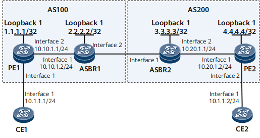
Networking Requirements
On the network shown in Figure 1, CE1 and CE2 access the MPLS backbone network through PE1 in AS100 and PE2 in AS200, respectively.
Inter-AS LDP VPWS Option A needs to be deployed for CE1 and CE2 to communicate.

Configuration Roadmap
The configuration roadmap is as follows:
Configure an IGP for each AS on the MPLS backbone network to ensure IP connectivity within the same AS.
Configure basic MPLS functions on the MPLS backbone network and establish a dynamic LSP between the PE and ASBR in the same AS. If the PE and ASBR are not directly connected, you also need to establish a remote MPLS LDP session between them.
Establish an LDP VPWS PW between the PE and ASBR in the same AS.
Data Preparation
To complete the configuration, you need the following data:
Peer IP addresses
Data for configuring the IGP
MPLS LSR IDs of PEs and ASBRs
L2VC IDs
Procedure
- Configure interface IP addresses.
# Configure CE1.
<HUAWEI> system-view
[~HUAWEI] sysname CE1
[*HUAWEI] commit
[~CE1] interface gigabitethernet 0/1/0
[*CE1-GigabitEthernet0/1/0] undo shutdown
[*CE1-GigabitEthernet0/1/0] ip address 10.1.1.1 24
[*CE1-GigabitEthernet0/1/0] quit
[*CE1] commit
# Configure PE1.
<HUAWEI> system-view
[~HUAWEI] sysname PE1
[*HUAWEI] commit
[~PE1] interface loopback1
[*PE1-Loopback1] ip address 1.1.1.1 32
[*PE1-Loopback1] quit
[*PE1] interface gigabitethernet 0/1/8
[*PE1-GigabitEthernet0/1/8] undo shutdown
[*PE1-GigabitEthernet0/1/8] ip address 10.10.1.1 24
[*PE1-GigabitEthernet0/1/8] quit
[*PE1] commit
# Configure ASBR1.
<HUAWEI> system-view
[~HUAWEI] sysname ASBR1
[*HUAWEI] commit
[~ASBR1] interface loopback1
[*ASBR1-Loopback1] ip address 2.2.2.2 32
[*ASBR1-Loopback1] quit
[*ASBR1] interface gigabitethernet 0/1/0
[*ASBR1-GigabitEthernet0/1/0] undo shutdown
[*ASBR1-GigabitEthernet0/1/0] ip address 10.10.1.2 24
[*ASBR1-GigabitEthernet0/1/0] quit
[*ASBR1] commit
# Configure ASBR2.
<HUAWEI> system-view
[~HUAWEI] sysname ASBR2
[*HUAWEI] commit
[~ASBR2] interface loopback1
[*ASBR2-Loopback1] ip address 3.3.3.3 32
[*ASBR2-Loopback1] quit
[*ASBR2] interface gigabitethernet 0/1/8
[*ASBR2-GigabitEthernet0/1/8] undo shutdown
[*ASBR2-GigabitEthernet0/1/8] ip address 10.20.1.1 24
[*ASBR2-GigabitEthernet0/1/8] quit
[*ASBR2] commit
# Configure PE2.
<HUAWEI> system-view
[~HUAWEI] sysname PE2
[*HUAWEI] commit
[~PE2] interface loopback1
[*PE2-Loopback1] ip address 4.4.4.4 32
[*PE2-Loopback1] quit
[*PE2] interface gigabitethernet 0/1/0
[*PE2-GigabitEthernet0/1/0] undo shutdown
[*PE2-GigabitEthernet0/1/0] ip address 10.20.1.2 24
[*PE2-GigabitEthernet0/1/0] quit
[*PE2] interface gigabitethernet 0/1/8
[*PE2-GigabitEthernet0/1/8] undo shutdown
[*PE2-GigabitEthernet0/1/8] quit
[*PE2] interface gigabitethernet 0/1/8.1
[*PE2-GigabitEthernet0/1/8.1] quit
[*PE2] commit
# Configure CE2.
<HUAWEI> system-view
[~HUAWEI] sysname CE2
[*HUAWEI] commit
[~CE2] interface gigabitethernet 0/1/0
[*CE2-GigabitEthernet0/1/0] undo shutdown
[*CE2-GigabitEthernet0/1/0] ip address 10.1.1.2 24
[*CE2-GigabitEthernet0/1/0] quit
[*CE2] commit
- Configure an IGP on the MPLS backbone network.
# Configure PE1.
[~PE1] ospf 1
[*PE1-ospf-1] area 0.0.0.0
[*PE1-ospf-1-area-0.0.0.0] network 1.1.1.1 0.0.0.0
[*PE1-ospf-1-area-0.0.0.0] network 10.10.1.0 0.0.0.255
[*PE1-ospf-1-area-0.0.0.0] quit
[*PE1-ospf-1] quit
[*PE1] commit
# Configure ASBR1.
[~ASBR1] ospf 1
[*ASBR1-ospf-1] area 0.0.0.0
[*ASBR1-ospf-1-area-0.0.0.0] network 2.2.2.2 0.0.0.0
[*ASBR1-ospf-1-area-0.0.0.0] network 10.10.1.0 0.0.0.255
[*ASBR1-ospf-1-area-0.0.0.0] quit
[*ASBR1-ospf-1] quit
[*ASBR1] commit
# Configure ASBR2.
[~ASBR2] ospf 1
[*ASBR2-ospf-1] area 0.0.0.0
[*ASBR2-ospf-1-area-0.0.0.0] network 3.3.3.3 0.0.0.0
[*ASBR2-ospf-1-area-0.0.0.0] network 10.20.1.0 0.0.0.255
[*ASBR2-ospf-1-area-0.0.0.0] quit
[*ASBR2-ospf-1] quit
[*ASBR2] commit
# Configure PE2.
[~PE2] ospf 1
[*PE2-ospf-1] area 0.0.0.0
[*PE2-ospf-1-area-0.0.0.0] network 4.4.4.4 0.0.0.0
[*PE2-ospf-1-area-0.0.0.0] network 10.20.1.0 0.0.0.255
[*PE2-ospf-1-area-0.0.0.0] quit
[*PE2-ospf-1] quit
[*PE2] commit
- Enable MPLS and establish LSPs.
# Configure PE1.
[~PE1] mpls lsr-id 1.1.1.1
[*PE1] mpls
[*PE1-mpls] quit
[*PE1] mpls ldp
[*PE1-mpls-ldp] quit
[*PE1] inerface gigabitethernet 0/1/8
[*PE1-GigabitEthernet0/1/8] mpls
[*PE1-GigabitEthernet0/1/8] mpls ldp
[*PE1-GigabitEthernet0/1/8] quit
[*PE1] commit
# Configure ASBR1.
[~ASBR1] mpls lsr-id 2.2.2.2
[*ASBR1] mpls
[*ASBR1-mpls] quit
[*ASBR1] mpls ldp
[*ASBR1-mpls-ldp] quit
[*ASBR1] inerface gigabitethernet 0/1/0
[*ASBR1-GigabitEthernet0/1/0] mpls
[*ASBR1-GigabitEthernet0/1/0] mpls ldp
[*ASBR1-GigabitEthernet0/1/0] quit
[*ASBR1] commit
# Configure ASBR2.
[~ASBR2] mpls lsr-id 3.3.3.3
[*ASBR2] mpls
[*ASBR2-mpls] quit
[*ASBR2] mpls ldp
[*ASBR2-mpls-ldp] quit
[*ASBR2] inerface gigabitethernet 0/1/8
[*ASBR2-GigabitEthernet0/1/8] mpls
[*ASBR2-GigabitEthernet0/1/8] mpls ldp
[*ASBR2-GigabitEthernet0/1/8] quit
[*ASBR2] commit
# Configure PE2.
[~PE2] mpls lsr-id 4.4.4.4
[*PE2] mpls
[*PE2-mpls] quit
[*PE2] mpls ldp
[*PE2-mpls-ldp] quit
[*PE2] inerface gigabitethernet 0/1/0
[*PE2-GigabitEthernet0/1/0] mpls
[*PE2-GigabitEthernet0/1/0] mpls ldp
[*PE2-GigabitEthernet0/1/0] quit
[*PE2] commit
- Configure an LDP VPWS PW between PE1 and PE2.
# Configure PE1.
[~PE1] mpls l2vpn
[*PE1-l2vpn] quit
[*PE1] interface gigabitethernet 0/1/0
[*PE1-GigabitEthernet0/1/0] mpls l2vc 2.2.2.2 100
[*PE1-GigabitEthernet0/1/0] undo shutdown
[*PE1-GigabitEthernet0/1/0] quit
[*PE1] commit
# Configure ASBR1.
[~ASBR1] mpls l2vpn
[*ASBR1-l2vpn] quit
[*ASBR1] interface gigabitethernet 0/1/8
[*ASBR1-GigabitEthernet0/1/8] mpls l2vc 1.1.1.1 100
[*ASBR1-GigabitEthernet0/1/8] undo shutdown
[*ASBR1-GigabitEthernet0/1/8] quit
[*ASBR1] commit
# Configure ASBR2.
[~ASBR2] mpls l2vpn
[*ASBR2-l2vpn] quit
[*ASBR2] interface gigabitethernet 0/1/0
[*ASBR2-GigabitEthernet0/1/0] mpls l2vc 4.4.4.4 100
[*ASBR2-GigabitEthernet0/1/0] undo shutdown
[*ASBR2-GigabitEthernet0/1/0] quit
[*ASBR2] commit
# Configure PE2.
[~PE2] mpls l2vpn
[*PE2-l2vpn] quit
[*PE2] interface gigabitethernet 0/1/8
[*PE2-GigabitEthernet0/1/8] mpls l2vc 3.3.3.3 100
[*PE2-GigabitEthernet0/1/8] undo shutdown
[*PE2-GigabitEthernet0/1/8] quit
[*PE2] commit
- Verify the configuration.
After completing the configurations, run the display mpls l2vc command on PE1 or PE2. The command output shows that a PW has been established and VC state is up. The following example uses the command output on PE1.
<~PE1> display mpls l2vc interface gigabitethernet 0/1/0
*client interface       : GigabitEthernet0/1/0 is up
 Administrator PW             : no
 session state                : up
 AC status                    : up
 VC state                     : up
 Label state                  : 0
 Token state                  : 0
 VC ID                        : 100
 VC type                      : VLAN
 destination                  : 2.2.2.2
 local group ID               : 0         remote group ID      : 0
 local VC label               : 18        remote VC label      : 18
 local AC OAM State           : up
 local PSN OAM State          : up
 local forwarding state       : forwarding
 local status code            : 0x0 (forwarding)
 remote AC OAM State          : up
 remote PSN OAM state         : up
 remote forwarding state      : forwarding
 remote status code           : 0x0 (forwarding)
 ignore standby state         : no
 Dynamic BFD for PW           : enable
 Detect Multipier             : 3
 Min Transit Interval         : 1000
 Min Receive Interval         : 1000
 Dynamic BFD Session          : built
 BFD for PW                   : available
   BFD sessionIndex           : --  BFD state : up
 VCCV State                   : --
 manual fault                 : not set
 active state                 : active
 forwarding entry             : exist
 OAM Protocol                 : --
 OAM Status                   : --
 OAM Fault Type               : --
 PW APS ID                    : --
 PW APS Status                : --
 TTL Value                    : 1
 link state                   : up
 local VC MTU                 : 1500      remote VC MTU        : 1500
 local VCCV                   : alert ttl lsp-ping bfd
 remote VCCV                  : alert ttl lsp-ping bfd
 local control word           : disable   remote control word  : disable
 tunnel policy name           : --
 PW template name             : --
 primary or secondary         : primary
 load balance type            : flow
 Access-port                  : false
 Switchover Flag              : false
 VC tunnel info               : 1 tunnels
    NO.0 TNL type             : ldp, TNL ID : 0x0000000001004c4b43
 create time                  : 0 days, 1 hours, 2 minutes, 56 seconds
 up time                      : 0 days, 1 hours, 1 minutes, 48 seconds
 last change time             : 0 days, 1 hours, 1 minutes, 48 seconds
 VC last up time              : 2012/12/05 02:50:41
 VC total up time             : 0 days, 1 hours, 1 minutes, 48 seconds
 CKey                         : 1
 NKey                         : 1493172332
 L2VPN QoS CIR value          : 3888
 L2VPN QoS PIR value          : 3888
 L2VPN QoS qos-profile name   : --
 PW redundancy mode           : frr
 AdminPw interface            : --
 AdminPw link state           : --
 Forward state                : send inactive, receive inactive
 Diffserv Mode                : uniform
 Service Class                : --
 Color                        : --
 DomainId                     : --
 Domain Name                  : --
CE1 and CE2 can ping each other. The following example uses the command output on CE1.
[~CE1] ping 10.1.1.2
  PING 10.1.1.2: 56  data bytes, press CTRL_C to break
    Reply from 10.1.1.2: bytes=56 Sequence=1 ttl=255 time=430 ms
    Reply from 10.1.1.2: bytes=56 Sequence=2 ttl=255 time=220 ms
    Reply from 10.1.1.2: bytes=56 Sequence=3 ttl=255 time=190 ms
    Reply from 10.1.1.2: bytes=56 Sequence=4 ttl=255 time=190 ms
    Reply from 10.1.1.2: bytes=56 Sequence=5 ttl=255 time=190 ms

  --- 10.1.1.2 ping statistics ---
    5 packet(s) transmitted
    5 packet(s) received
    0.00% packet loss
    round-trip min/avg/max = 190/244/430 ms
Configuration Files
CE1 configuration file
#
sysname CE1
#
interface GigabitEthernet0/1/0
 undo shutdown
 ip address 10.1.1.1 255.255.255.0
#
return
PE1 configuration file
#
sysname PE1
#
mpls lsr-id 1.1.1.1
mpls
#
mpls l2vpn
#
mpls ldp
#
interface GigabitEthernet0/1/0
 undo shutdown
 mpls l2vc 2.2.2.2 100
#
interface GigabitEthernet0/1/8
 undo shutdown
 ip address 10.10.1.1 255.255.255.0
 mpls
 mpls ldp
#
interface LoopBack1
 ip address 1.1.1.1 255.255.255.255
#
ospf 1
 area 0.0.0.0
  network 1.1.1.1 0.0.0.0
  network 10.10.1.0 0.0.0.255
#
return
ASBR1 configuration file
#
sysname ASBR1
#
mpls lsr-id 2.2.2.2
mpls
#
mpls l2vpn
#
mpls ldp
#
interface GigabitEthernet0/1/0
 undo shutdown
 ip address 10.10.1.2 255.255.255.0
 mpls
 mpls ldp
#
interface GigabitEthernet0/1/8
 undo shutdown
 mpls l2vc 1.1.1.1 100
#
interface LoopBack1
 ip address 2.2.2.2 255.255.255.255
#
ospf 1
 area 0.0.0.0
  network 2.2.2.2 0.0.0.0
  network 10.10.1.0 0.0.0.255
#
return
ASBR2 configuration file
#
sysname ASBR2
#
mpls lsr-id 3.3.3.3
mpls
#
mpls l2vpn
#
mpls ldp
#
interface GigabitEthernet0/1/0
 undo shutdown
 mpls l2vc 4.4.4.4 100
#
interface GigabitEthernet0/1/8
 undo shutdown
 ip address 10.20.1.1 255.255.255.0
 mpls
 mpls ldp
#
interface LoopBack1
 ip address 3.3.3.3 255.255.255.255
#
ospf 1
 area 0.0.0.0
  network 3.3.3.3 0.0.0.0
  network 10.20.1.0 0.0.0.255
#
return
PE2 configuration file
#
sysname PE2
#
mpls lsr-id 4.4.4.4
mpls
#
mpls l2vpn
#
mpls ldp
#
interface GigabitEthernet0/1/0
 undo shutdown
 ip address 10.20.1.2 255.255.255.0
 mpls
 mpls ldp
#
interface GigabitEthernet0/1/8
 undo shutdown
 mpls l2vc 3.3.3.3 100
#
interface LoopBack1
 ip address 4.4.4.4 255.255.255.255
#
ospf 1
 area 0.0.0.0
  network 4.4.4.4 0.0.0.0
  network 10.20.1.0 0.0.0.255
#
return
CE2 configuration file
#
sysname CE2
#
interface GigabitEthernet0/1/0
 undo shutdown
 ip address 10.1.1.2 255.255.255.0
#
return