Example for Configuring SVC VPWS
An SVC VPWS is a static VPWS, which requires no signaling protocol, but configured VC labels to transmit L2VPN information.
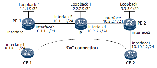
Networking Requirements
Figure 1 shows SVC L2VPN is established between CE1 and CE2. The SVC connection is created on PE and the VC label is assigned.
Configuration Roadmap
The configuration roadmap is as follows:
Enable MPLS and the MPLS L2VPN.
Create the L2VC connection between PEs and configure the VC label information manually.
Data Preparation
To complete the configuration, you need the label value of the static L2VC connection.

The outer label of PE1 is the same as the inner label of PE2; the inner label of PE1 is the same as the outer label of PE2.
Procedure
- Configure interface addresses for CE, PE and P as shown in Figure 1.
The specific configuration procedures are not mentioned here.
- Configure IGP on MPLS backbone network. (OSPF is used in this instance.)
During the OSPF configuration, the 32-bit loopback interface addresses, functioning as LSR IDs for PE1, P and PE2 needs to be advertised.
The specific configuration procedures are omitted here.
- Configure MPLS basic capability and LDP on MPLS backbone network, using the LDP LSP tunnel.
# Configure PE1.
[~PE1] mpls lsr-id 1.1.1.9
[*PE1] mpls
[*PE1-mpls] quit
[*PE1] mpls ldp
[*PE1-mpls-ldp] quit
[*PE1] mpls ldp remote-peer 3.3.3.9
[*PE1-mpls-ldp-remote-3.3.3.9] remote-ip 3.3.3.9
[*PE1-mpls-ldp-remote-3.3.3.9] quit
[*PE1] interface gigabitethernet 0/1/8
[*PE1-GigabitEthernet0/1/8] mpls
[*PE1-GigabitEthernet0/1/8] mpls ldp
[*PE1-GigabitEthernet0/1/8] quit
[*PE1] commit
# Configure P.
[~P] mpls lsr-id 2.2.2.9
[*P] mpls
[*P-mpls] quit
[*P] mpls ldp
[*P-mpls-ldp] quit
[*P] interface gigabitethernet 0/1/0
[*P-GigabitEthernet0/1/0] mpls
[*P-GigabitEthernet0/1/0] mpls ldp
[*P-GigabitEthernet0/1/0] quit
[*P] interface gigabitethernet0/1/8
[*P-GigabitEthernet0/1/8] mpls
[*P-GigabitEthernet0/1/8] mpls ldp
[*P-GigabitEthernet0/1/8] quit
[*P] commit
# Configure PE2.
[~PE2] mpls lsr-id 3.3.3.9
[*PE2] mpls
[*PE2-mpls] quit
[*PE2] mpls ldp
[*PE2-mpls-ldp] quit
[*PE2] interface gigabitethernet 0/1/0
[*PE2-GigabitEthernet0/1/0] mpls
[*PE2-GigabitEthernet0/1/0] mpls ldp
[*PE2-GigabitEthernet0/1/0] quit
[*PE2] commit
After the configuration, LDP sessions are set up between PE1, P, and PE2. Run the display mpls ldp session command, and you can view that the status of the LDP session is Operational.
The following example uses the command output on PE1.
<PE1> display mpls ldp session LDP Session(s) in Public Network Codes: LAM(Label Advertisement Mode), SsnAge Unit(DDDD:HH:MM) An asterisk (*) before a session means the session is being deleted. ------------------------------------------------------------------------------ PeerID Status LAM SsnRole SsnAge KASent/Rcv ------------------------------------------------------------------------------ 2.2.2.9:0 Operational DU Passive 000:02:22 572/572 3.3.3.9:0 Operational DU Passive 000:02:21 566/566 ------------------------------------------------------------------------------ TOTAL: 2 session(s) Found. - Enable MPLS L2VPN on PE and creating a static VC connection.
# On PE1, create a static VC on GE 0/1/0 that connects CE1.
[~PE1] mpls l2vpn
[*PE1-l2vpn] quit
[*PE1] interface gigabitethernet 0/1/0
[*PE1-GigabitEthernet0/1/0] mpls static-l2vc destination 3.3.3.9 transmit-vpn-label 100 receive-vpn-label 200
[*PE1-GigabitEthernet0/1/0] undo shutdown
[*PE1-GigabitEthernet0/1/0] quit
[*PE1] commit
# On PE2, create a static VC on GE 0/1/8 that connects CE2.
[~PE2] mpls l2vpn
[*PE2-l2vpn] quit
[*PE2] mpls ldp remote-peer 1.1.1.9
[*PE2-mpls-ldp-remote-1.1.1.9] remote-ip 1.1.1.9
[*PE2-mpls-ldp-remote-1.1.1.9] quit
[*PE2] interface gigabitethernet 0/1/8
[*PE2-GigabitEthernet0/1/8] mpls static-l2vc destination 1.1.1.9 transmit-vpn-label 200 receive-vpn-label 100
[*PE2-GigabitEthernet0/1/8] undo shutdown
[*PE2-GigabitEthernet0/1/8] quit
[*PE2] commit
- Verify the configuration.
Check information about the SVC L2VPN connection on PEs. You can find that a static L2VC is set up.
The following example uses the command output on PE1.
<PE1> display mpls static-l2vc interface gigabitethernet 0/1/0
 *Client Interface   : GigabitEthernet0/1/0 is up
  AC Status          : up
  VC State           : up
  VC ID              : 0
  VC Type            : Ethernet
  Destination        : 3.3.3.9
  Transmit VC Label  : 100
  Receive VC Label   : 200
  Label Status       : 0
  Token Status       : 0
  Control Word       : Disable
  VCCV Capability    : alert lsp-ping bfd
  active state       : active
  OAM Protocol       : --
  OAM Status         : --
  OAM Fault Type     : --
  PW APS ID          : --
  PW APS Status      : --
  TTL Value          : 1
  Link State         : up
  Tunnel Policy      : --
  PW Template Name   : --
  Traffic Behavior   : --
  Main or Secondary  : Main
  VC tunnel/token info : 1 tunnels/tokens
  NO.0  TNL Type : lsp   , TNL ID : 0x2002002
  Create time          : 0 days, 0 hours, 8 minutes, 2 seconds
  UP time              : 0 days, 0 hours, 6 minutes, 12 seconds
  Last change time     : 0 days, 0 hours, 6 minutes, 12 seconds
  VC last up time : 2008-07-24 12:31:31
  VC total up time: 0 days, 2 hours, 12 minutes, 51 seconds
  CKey                 : 17
  NKey                 : 18
Run the display l2vpn ccc-interface vc-type static-vc up command, and you can find that the VC type is SVC and the status is Up. The following example uses the command output on PE1.
<PE1> display l2vpn ccc-interface vc-type static-vc up
Total ccc-interface of SVC VC: 1
up (1), down (0)
Interface                     Encap Type               State     VC Type
GigabitEthernet0/1/0                      ethernet                      up          static-vc
CE1 and CE2 can successfully ping each other.
<CE1> ping 10.10.1.2
  PING 10.10.1.2: 56  data bytes, press CTRL_C to break
    Reply from 10.10.1.2: bytes=56 Sequence=1 ttl=255 time=46 ms
    Reply from 10.10.1.2: bytes=56 Sequence=2 ttl=255 time=91 ms
    Reply from 10.10.1.2: bytes=56 Sequence=3 ttl=255 time=74 ms
    Reply from 10.10.1.2: bytes=56 Sequence=4 ttl=255 time=88 ms
    Reply from 10.10.1.2: bytes=56 Sequence=5 ttl=255 time=82 ms
  --- 10.10.1.2 ping statistics ---
    5 packet(s) transmitted
    5 packet(s) received
    0.00% packet loss
    round-trip min/avg/max = 46/76/91 ms
Configuration Files
CE1 configuration file
#
 sysname CE1
#
interface GigabitEthernet0/1/0
 undo shutdown
 ip address 10.10.1.1 255.255.255.0
#
return
PE1 configuration file
#
 sysname PE1
#
 mpls lsr-id 1.1.1.9
 mpls
#
 mpls l2vpn
#
mpls ldp
#
mpls ldp remote-peer 3.3.3.9
 remote-ip 3.3.3.9
#
interface GigabitEthernet0/1/0
 undo shutdown
 mpls static-l2vc destination 3.3.3.9 transmit-vpn-label 100 receive-vpn-label 200
#
interface GigabitEthernet0/1/8
 undo shutdown
 ip address 10.1.1.1 255.255.255.0
 mpls
 mpls ldp
#
interface LoopBack1
 ip address 1.1.1.9 255.255.255.255
#
ospf 1
 area 0.0.0.0
  network 1.1.1.9 0.0.0.0
  network 10.1.1.0 0.0.0.255
#
return
P configuration file
#
 sysname P
#
 mpls lsr-id 2.2.2.9
 mpls
#
mpls ldp
#

interface GigabitEthernet0/1/0
 undo shutdown
 ip address 10.2.2.2 255.255.255.0
 mpls
 mpls ldp
#
interface GigabitEthernet0/1/8
 undo shutdown
 ip address 10.1.1.2 255.255.255.0
 mpls
 mpls ldp
#
interface LoopBack1
 ip address 2.2.2.9 255.255.255.255
#
ospf 1
 area 0.0.0.0
  network 2.2.2.9 0.0.0.0
  network 10.1.1.0 0.0.0.255
  network 10.2.2.0 0.0.0.255
#
return
PE2 configuration file
#
 sysname PE2
#
 mpls lsr-id 3.3.3.9
 mpls
#
 mpls l2vpn
#
mpls ldp
#
interface GigabitEthernet0/1/0
 undo shutdown
 ip address 10.2.2.1 255.255.255.0
 mpls
 mpls ldp
#
mpls ldp remote-peer 1.1.1.9
 remote-ip 1.1.1.9
#
interface GigabitEthernet0/1/8
 undo shutdown
 mpls static-l2vc destination 1.1.1.9 transmit-vpn-label 200 receive-vpn-label 100
#
interface LoopBack1
 ip address 3.3.3.9 255.255.255.255
#
ospf 1
 area 0.0.0.0
  network 3.3.3.9 0.0.0.0
  network 10.2.2.0 0.0.0.255
#
return
CE2 configuration file
#
 sysname CE2
#
interface GigabitEthernet0/1/0
 undo shutdown
 ip address 10.10.1.2 255.255.255.0
#
return