Example for Configuring Inter-AS BGP VPWS Option C
This section provides an example for configuring inter-AS BGP VPWS Option C. In inter-AS BGP VPWS Option C, ASBRs do not need to create or maintain VCs. This solution is recommended for scenarios where large numbers of inter-AS VPWS PWs are required.
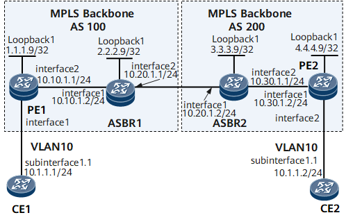
Networking Requirements
On the network shown in Figure 1, CE1 and CE2 access the MPLS backbone network through PE1 in AS100 and PE2 in AS200, respectively.
Inter-AS LDP VPWS Option C needs to be deployed for CE1 and CE2 to communicate. In inter-AS BGP VPWS Option C, PEs directly exchange VPWS label blocks, and ASBRs do not maintain VPWS label blocks.
Configuration Roadmap
The configuration roadmap is as follows:
Configure an IGP for each AS on the MPLS backbone network to ensure IP connectivity within the same AS.
Configure basic MPLS functions on the MPLS backbone network and establish a dynamic LSP between the PE and ASBR in the same AS. (ASBR interfaces also need to have basic MPLS functions configured.)
Establish an IBGP peer relationship between the PE and ASBR in the same AS.
Specify EBGP peers, configure routing policies, and enable label-based routing on ASBRs. Establish an MP-EBGP peer relationship between PE1 and PE2.
Configure VSIs on PEs and bind the corresponding AC interfaces to the VSIs.
Data Preparation
To complete the configuration, you need the following data:
MPLS LSR IDs of the PEs and ASBRs
Name, RD, and VPN targets of each VSI
AC interfaces bound to VSIs
Routing policies used by ASBRs
Procedure
- Configure interface IP addresses.
# Configure CE1.
<HUAWEI> system-view
[~HUAWEI] sysname CE1
[*HUAWEI] commit
[*CE1] interface gigabitethernet 0/1/0.1
[*CE1-GigabitEthernet0/1/0.1] ip address 10.1.1.1 24
[*CE1-GigabitEthernet0/1/0.1] quit
[*CE1] commit
# Configure PE1.
<HUAWEI> system-view
[~HUAWEI] sysname PE1
[*HUAWEI] commit
[~PE1] interface loopback1
[*PE1-Loopback1] ip address 1.1.1.9 32
[*PE1-Loopback1] quit
[*PE1] interface gigabitethernet 0/1/8
[*PE1-GigabitEthernet0/1/8] undo shutdown
[*PE1-GigabitEthernet0/1/8] ip address 10.10.1.1 24
[*PE1-GigabitEthernet0/1/8] quit
[*PE1] commit
# Configure ASBR1.
<HUAWEI> system-view
[~HUAWEI] sysname ASBR1
[*HUAWEI] commit
[~ASBR1] interface loopback1
[*ASBR1-Loopback1] ip address 2.2.2.9 32
[*ASBR1-Loopback1] quit
[*ASBR1] interface gigabitethernet 0/1/0
[*ASBR1-GigabitEthernet0/1/0] undo shutdown
[*ASBR1-GigabitEthernet0/1/0] ip address 10.10.1.2 24
[*ASBR1-GigabitEthernet0/1/0] quit
[*ASBR1] interface gigabitethernet 0/1/8
[*ASBR1-GigabitEthernet0/1/8] undo shutdown
[*ASBR1-GigabitEthernet0/1/8] ip address 10.20.1.1 24
[*ASBR1-GigabitEthernet0/1/8] quit
[*ASBR1] commit
# Configure ASBR2.
<HUAWEI> system-view
[~HUAWEI] sysname ASBR2
[*HUAWEI] commit
[~ASBR2] interface loopback1
[*ASBR2-Loopback1] ip address 3.3.3.9 32
[*ASBR2-Loopback1] quit
[*ASBR2] interface gigabitethernet 0/1/0
[*ASBR2-GigabitEthernet0/1/0] undo shutdown
[*ASBR2-GigabitEthernet0/1/0] ip address 10.20.1.2 24
[*ASBR2-GigabitEthernet0/1/0] quit
[*ASBR2] interface gigabitethernet 0/1/8
[*ASBR2-GigabitEthernet0/1/8] undo shutdown
[*ASBR2-GigabitEthernet0/1/8] ip address 10.30.1.1 24
[*ASBR2-GigabitEthernet0/1/8] quit
[*ASBR2] commit
# Configure PE2.
<HUAWEI> system-view
[~HUAWEI] sysname PE2
[*HUAWEI] commit
[~PE2] interface loopback1
[*PE2-Loopback1] ip address 4.4.4.9 32
[*PE2-Loopback1] quit
[*PE2] interface gigabitethernet 0/1/0
[*PE2-GigabitEthernet0/1/0] undo shutdown
[*PE2-GigabitEthernet0/1/0] ip address 10.30.1.2 24
[*PE2-GigabitEthernet0/1/0] quit
[*PE2] commit
# Configure CE2.
<HUAWEI> system-view
[~HUAWEI] sysname CE2
[*HUAWEI] commit
[*CE2] interface gigabitethernet 0/1/0.1
[*CE2-GigabitEthernet0/1/0.1] ip address 10.1.1.2 24
[*CE2-GigabitEthernet0/1/0.1] quit
[*CE2] commit
- Configure an IGP on the MPLS backbone network.
# Configure PE1.
[~PE1] ospf 1
[*PE1-ospf-1] area 0.0.0.0
[*PE1-ospf-1-area-0.0.0.0] network 1.1.1.9 0.0.0.0
[*PE1-ospf-1-area-0.0.0.0] network 10.10.1.0 0.0.0.255
[*PE1-ospf-1-area-0.0.0.0] quit
[*PE1-ospf-1] quit
[*PE1] commit
# Configure ASBR1.
[~ASBR1] ospf 1
[*ASBR1-ospf-1] area 0.0.0.0
[*ASBR1-ospf-1-area-0.0.0.0] network 2.2.2.9 0.0.0.0
[*ASBR1-ospf-1-area-0.0.0.0] network 10.10.1.0 0.0.0.255
[*ASBR1-ospf-1-area-0.0.0.0] quit
[*ASBR1-ospf-1] quit
[*ASBR1] commit
# Configure ASBR2.
[*ASBR2] ospf 1
[*ASBR2-ospf-1] area 0.0.0.0
[*ASBR2-ospf-1-area-0.0.0.0] network 3.3.3.9 0.0.0.0
[*ASBR2-ospf-1-area-0.0.0.0] network 10.30.1.0 0.0.0.255
[*ASBR2-ospf-1-area-0.0.0.0] quit
[*ASBR2-ospf-1] quit
[*ASBR2] commit
# Configure PE2.
[~PE2] ospf 1
[*PE2-ospf-1] area 0.0.0.0
[*PE2-ospf-1-area-0.0.0.0] network 4.4.4.9 0.0.0.0
[*PE2-ospf-1-area-0.0.0.0] network 10.30.1.0 0.0.0.255
[*PE2-ospf-1-area-0.0.0.0] quit
[*PE2-ospf-1] quit
[*PE2] commit
- Configure basic MPLS functions and establish LSPs.
# Configure PE1.
[~PE1] mpls lsr-id 1.1.1.9
[*PE1] mpls
[*PE1-mpls] quit
[*PE1] mpls ldp
[*PE1-mpls-ldp] quit
[*PE1] inerface gigabitethernet 0/1/8
[*PE1-GigabitEthernet0/1/8] mpls
[*PE1-GigabitEthernet0/1/8] mpls ldp
[*PE1-GigabitEthernet0/1/8] quit
[*PE1] commit
# Configure ASBR1.
[*ASBR1] mpls lsr-id 2.2.2.9
[*ASBR1] mpls
[*ASBR1-mpls] quit
[*ASBR1] mpls ldp
[*ASBR1-mpls-ldp] quit
[*ASBR1] inerface gigabitethernet 0/1/0
[*ASBR1-GigabitEthernet0/1/0] mpls
[*ASBR1-GigabitEthernet0/1/0] mpls ldp
[*ASBR1-GigabitEthernet0/1/0] quit
[*ASBR1] commit
# Configure ASBR2.
[~ASBR2] mpls lsr-id 3.3.3.9
[*ASBR2] mpls
[*ASBR2-mpls] quit
[*ASBR2] mpls ldp
[*ASBR2-mpls-ldp] quit
[*ASBR2] inerface gigabitethernet 0/1/8
[*ASBR2-GigabitEthernet0/1/8] mpls
[*ASBR2-GigabitEthernet0/1/8] mpls ldp
[*ASBR2-GigabitEthernet0/1/8] quit
[*ASBR2] commit
# Configure PE2.
[~PE2] mpls lsr-id 4.4.4.9
[*PE2] mpls
[*PE2-mpls] quit
[*PE2] mpls ldp
[*PE2-mpls-ldp] quit
[*PE2] inerface gigabitethernet 0/1/0
[*PE2-GigabitEthernet0/1/0] mpls
[*PE2-GigabitEthernet0/1/0] mpls ldp
[*PE2-GigabitEthernet0/1/0] quit
[*PE2] commit
- Enable inter-AS MPLS on ASBRs.
# Configure ASBR1.
[~ASBR1] inerface gigabitethernet 0/1/8
[*ASBR1-GigabitEthernet0/1/8] mpls
[*ASBR1-GigabitEthernet0/1/8-mpls] quit
[*ASBR1] commit
# Configure ASBR2.
[~ASBR2] inerface gigabitethernet 0/1/0
[*ASBR2-GigabitEthernet0/1/0] mpls
[*ASBR2-GigabitEthernet0/1/0-mpls] quit
[*ASBR2] commit
- Establish an MP-IBGP peer relationship between the PE and ASBR in the same AS, set up an MP-EBGP peer relationship between ASBRs, and configure routing policies on ASBRs. These routing policies ensure that an ASBR reallocates MPLS labels to labeled IPv4 routes to be advertised to local PEs and allocates MPLS labels to routes to be advertised to the peer ASBR.
# Configure PE1.
[~PE1] bgp 100
[*PE1-bgp] peer 2.2.2.9 as-number 100
[*PE1-bgp] peer 2.2.2.9 label-route-capability
[*PE1-bgp] peer 2.2.2.9 connect-interface LoopBack 1
[*PE1-bgp] quit
[*PE1] commit
# Configure ASBR1.
[~ASBR1] route-policy policy1 permit node 1
[*ASBR1-route-policy] if-match mpls-label
[*ASBR1-route-policy] apply mpls-label
[*ASBR1-route-policy] quit
[*ASBR1] route-policy policy2 permit node 1
[*ASBR1-route-policy] apply mpls-label
[*ASBR1-route-policy] quit
[*ASBR1] bgp 100
[*ASBR1-bgp] network 1.1.1.9 255.255.255.255
[*ASBR1-bgp] peer 1.1.1.9 as-number 100
[*ASBR1-bgp] peer 1.1.1.9 route-policy policy1 export
[*ASBR1-bgp] peer 1.1.1.9 label-route-capability
[*ASBR1-bgp] peer 1.1.1.9 connect-interface loopback 1
[*ASBR1-bgp] peer 10.20.1.2 as-number 200
[*ASBR1-bgp] peer 10.20.1.2 route-policy policy2 export
[*ASBR1-bgp] peer 10.20.1.2 label-route-capability check-tunnel-reachable
[*ASBR1-bgp] peer 10.20.1.2 connect-interface gigabitethernet 0/1/8
[*ASBR1-bgp]quit
[*ASBR1]commit
# Configure ASBR2.
[~ASBR2] route-policy policy1 permit node 1
[*ASBR2-route-policy] if-match mpls-label
[*ASBR2-route-policy] apply mpls-label
[*ASBR2-route-policy] quit
[*ASBR2] route-policy policy2 permit node 1
[*ASBR2-route-policy] apply mpls-label
[*ASBR2-route-policy] quit
[*ASBR2] bgp 200
[*ASBR2-bgp] network 4.4.4.9 255.255.255.255
[*ASBR2-bgp] peer 4.4.4.9 as-number 200
[*ASBR2-bgp] peer 4.4.4.9 route-policy policy1 export
[*ASBR2-bgp] peer 4.4.4.9 label-route-capability
[*ASBR2-bgp] peer 4.4.4.9 connect-interface loopback 1
[*ASBR2-bgp] peer 10.20.1.1 as-number 100
[*ASBR2-bgp] peer 10.20.1.1 route-policy policy2 export
[*ASBR2-bgp] peer 10.20.1.1 label-route-capability check-tunnel-reachable
[*ASBR2-bgp] peer 10.20.1.1 connect-interface gigabitethernet 0/1/0
[*ASBR2-bgp] quit
[*ASBR2] commit
# Configure PE2.
[~PE2] bgp 200
[*PE2-bgp] peer 3.3.3.9 as-number 200
[*PE2-bgp] peer 3.3.3.9 label-route-capability
[*PE2-bgp] peer 3.3.3.9 connect-interface loopback 1
[*PE2-bgp] quit
[*PE2] commit
- Establish an MP-EBGP peer relationship between PE1 and PE2.

The capability to exchange route information with BGP peers must be configured in the L2VPN-AD address family view for PEs to exchange VPWS label block information.
# Configure PE1.
[~PE1] bgp 100
[*PE1-bgp] peer 4.4.4.9 as-number 200
[*PE1-bgp] peer 4.4.4.9 ebgp-max-hop 255
[*PE1-bgp] peer 4.4.4.9 connect-interface loopback 1
[*PE1-bgp] l2vpn-ad-family
[*PE1-bgp-af-l2vpn-ad] peer 4.4.4.9 enable
[*PE1-bgp-af-l2vpn-ad] peer 4.4.4.9 signaling VPWS
[*PE1-bgp-af-l2vpn-ad] quit
[*PE1-bgp] quit
[*PE1] commit
# Configure PE2.
[~PE2] bgp 200
[*PE2-bgp] peer 1.1.1.9 as-number 100
[*PE2-bgp] peer 1.1.1.9 ebgp-max-hop 255
[*PE2-bgp] peer 1.1.1.9 connect-interface loopback 1
[*PE2-bgp] l2vpn-ad-family
[*PE2-bgp-af-l2vpn-ad] peer 1.1.1.9 enable
[*PE2-bgp-af-l2vpn-ad] peer 1.1.1.9 signaling VPWS
[*PE2-bgp-af-l2vpn-ad] quit
[*PE2-bgp] quit
[*PE2] commit
Run the display tunnel-info all command on PE1 or PE2. The command output shows that an inter-AS LSP has been established between PE1 and PE2. The following example uses the command output on PE1.
[~PE1] display tunnel-info all Tunnel ID Type Destination Status ----------------------------------------------------------------------------- 0x0000000001004c8b42 ldp 2.2.2.9 UP 0x000000000201040000 bgp 4.4.4.9 UP - Configure a BGP connection.
# Configure PE1.
[~PE1] mpls l2vpn
[*PE1-l2vpn] quit
[*PE1] mpls l2vpn vpn1 encapsulation ethernet
[*PE1-mpls-l2vpn-vpn1] route-distinguisher 100:1
[*PE1-mpls-l2vpn-vpn1] vpn-target 1:1 both
[*PE1-mpls-l2vpn-vpn1] ce ce1 id 1 range 10
[*PE1-mpls-l2vpn-vpn1-ce-ce1] connection ce-offset 2 interface gigabitethernet 0/1/0
[*PE1-mpls-l2vpn-vpn1-ce-ce1] quit
[*PE1-mpls-l2vpn-vpn1] quit
[*PE1] commit
# Configure PE2.
[~PE2] mpls l2vpn
[*PE2-l2vpn] quit
[*PE2] mpls l2vpn vpn1 encapsulation ethernet
[*PE2-mpls-l2vpn-vpn1] route-distinguisher 100:1
[*PE2-mpls-l2vpn-vpn1] vpn-target 1:1 both
[*PE2-mpls-l2vpn-vpn1] ce ce2 id 2 range 10
[*PE2-mpls-l2vpn-vpn1-ce-ce2] connection ce-offset 1 interface gigabitethernet 0/1/8
[*PE2-mpls-l2vpn-vpn1-ce-ce2] quit
[*PE2-mpls-l2vpn-vpn1] quit
[*PE2] commit
- Verify the configuration.
Check VPWS information on PE1. The command output shows that the VSI status is Up. The PW to the remote PE is also Up. The PW is carried over the previously established inter-AS LSP. The following example uses the command output on PE1.
[~PE1] display mpls l2vpn connection interface gigabitethernet 0/1/0
conn-type: remote
     local vc state:             up
     remote vc state:            up
     local ce-id:                1
     local ce name:              ce1
     remote ce-id:               2
     intf(state,encap):          GigabitEthernet0/1/0(up,ethernet)
     peer id:                    4.4.4.9
     route-distinguisher:        100:1
     local vc label:             294930
     remote vc label:            294929
     tunnel policy:              default
     CKey:                       129
     NKey:                       3841982621
     primary or secondary:       primary
     forward entry exist or not: true
     forward entry active or not:true
     manual fault set or not:    not set
     AC OAM state:               up
     BFD for PW session index:   --
     BFD for PW state:           invalid
     BFD for LSP state:          true
     Local C bit is not set
     Remote C bit is not set
     tunnel type:                bgp
     tunnel id:                  0x000000000201040000
CE1 and CE2 can ping each other. The following example uses the command output on CE1.
[~CE1] ping 10.1.1.2
 PING 10.1.1.2: 56  data bytes, press CTRL_C to break
    Reply from 10.1.1.2: bytes=56 Sequence=1 ttl=255 time=8 ms
    Reply from 10.1.1.2: bytes=56 Sequence=2 ttl=255 time=4 ms
    Reply from 10.1.1.2: bytes=56 Sequence=3 ttl=255 time=4 ms
    Reply from 10.1.1.2: bytes=56 Sequence=4 ttl=255 time=7 ms
    Reply from 10.1.1.2: bytes=56 Sequence=5 ttl=255 time=3 ms

  --- 10.1.1.2 ping statistics ---
    5 packet(s) transmitted
    5 packet(s) received
    0.00% packet loss
    round-trip min/avg/max = 3/5/8 ms
Configuration Files
CE1 configuration file
#
sysname CE1
#
interface GigabitEthernet0/1/0
 undo shutdown
#
interface GigabitEthernet0/1/0.1
 undo shutdown
 vlan-type dot1q 10
 ip address 10.1.1.1 255.255.255.0
#
return
PE1 configuration file
#
sysname PE1
#
mpls lsr-id 1.1.1.9
#
mpls
#
mpls l2vpn
#
mpls ldp
#
interface GigabitEthernet0/1/8
 undo shutdown
 ip address 10.10.1.1 255.255.255.0
 mpls
 mpls ldp
#
interface LoopBack1
 ip address 1.1.1.9 255.255.255.255
#
#
mpls l2vpn vpn1 encapsulation ethernet
 route-distinguisher 100:1
 vpn-target 1:1 import-extcommunity
 vpn-target 1:1 export-extcommunity
 ce ce1 id 1 range 10 default-offset 0
  connection ce-offset 2 interface GigabitEthernet0/1/0
#
bgp 100
 peer 2.2.2.9 as-number 100
 peer 2.2.2.9 connect-interface LoopBack1
 peer 4.4.4.9 as-number 200
 peer 4.4.4.9 ebgp-max-hop 255
 peer 4.4.4.9 connect-interface LoopBack1
 #
 ipv4-family unicast
  undo synchronization
  peer 2.2.2.9 enable
  peer 2.2.2.9 label-route-capability
  peer 4.4.4.9 enable
 #
 l2vpn-ad-family
  policy vpn-target
  peer 4.4.4.9 enable
  peer 4.4.4.9 signaling vpws
#
ospf 1
 area 0.0.0.0
  network 1.1.1.9 0.0.0.0
  network 10.10.1.0 0.0.0.255
#
return
ASBR1 configuration file
#
sysname ASBR1
#
mpls lsr-id 2.2.2.9
#
mpls
#
mpls ldp
#
interface GigabitEthernet0/1/0
 undo shutdown
 ip address 10.10.1.2 255.255.255.0
 mpls
 mpls ldp
#
interface GigabitEthernet0/1/8
 undo shutdown
 ip address 10.20.1.1 255.255.255.0
#
interface LoopBack1
 ip address 2.2.2.9 255.255.255.255
#
bgp 100
 peer 1.1.1.9 as-number 100
 peer 1.1.1.9 connect-interface LoopBack1
 peer 10.20.1.2 as-number 200
 peer 10.20.1.2 connect-interface GigabitEthernet0/1/8
 #
 ipv4-family unicast
  undo synchronization
  network 1.1.1.9 255.255.255.255
  peer 1.1.1.9 enable
  peer 1.1.1.9 route-policy policy1 export
  peer 1.1.1.9 label-route-capability
  peer 10.20.1.2 enable
  peer 10.20.1.2 route-policy policy2 export
  peer 10.20.1.2 label-route-capability check-tunnel-reachable
#
ospf 1
 area 0.0.0.0
  network 2.2.2.9 0.0.0.0
  network 10.10.1.0 0.0.0.255
#
route-policy policy1 permit node 1
 if-match mpls-label
 apply mpls-label
#
route-policy policy2 permit node 1
 apply mpls-label
#
return
ASBR2 configuration file
#
sysname ASBR2
#
mpls lsr-id 3.3.3.9
#
mpls
#
mpls ldp
#
interface GigabitEthernet0/1/0
 undo shutdown
 ip address 10.20.1.2 255.255.255.0
#
interface GigabitEthernet0/1/8
 undo shutdown
 ip address 10.30.1.1 255.255.255.0
 mpls
 mpls ldp
#
interface LoopBack1
 ip address 3.3.3.9 255.255.255.0
#
bgp 200
 peer 4.4.4.9 as-number 200
 peer 4.4.4.9 connect-interface LoopBack1
 peer 10.20.1.1 as-number 100
 peer 10.20.1.1 connect-interface GigabitEthernet0/1/0
 #
 ipv4-family unicast
  undo synchronization
  network 4.4.4.9 255.255.255.255
  peer 4.4.4.9 enable
  peer 4.4.4.9 route-policy policy1 export
  peer 4.4.4.9 label-route-capability
  peer 10.20.1.1 enable
  peer 10.20.1.1 route-policy policy2 export
  peer 10.20.1.1 label-route-capability check-tunnel-reachable
#
ospf 1
 area 0.0.0.0
  network 3.3.3.9 0.0.0.0
  network 10.30.1.0 0.0.0.255
#
route-policy policy1 permit node 1
 if-match mpls-label
 apply mpls-label
#
route-policy policy2 permit node 1
 apply mpls-label
#
return
PE2 configuration file
#
sysname PE2
#
mpls lsr-id 4.4.4.9
#
mpls
#
mpls l2vpn
#
mpls ldp
#
interface GigabitEthernet0/1/0
 undo shutdown
 ip address 10.30.1.2 255.255.255.0
 mpls
 mpls ldp
#


interface LoopBack1
 ip address 4.4.4.9 255.255.255.0
#
mpls l2vpn vnp1 encapsulation ethernet
 route-distinguisher 100:1
 vpn-target 1:1 import-extcommunity
 vpn-target 1:1 export-extcommunity
 ce ce2 id 2 range 10 default-offset 0
  connection ce-offset 1 interface GigabitEthernet0/1/8
#
bgp 200
 peer 1.1.1.9 as-number 100
 peer 1.1.1.9 ebgp-max-hop 255
 peer 1.1.1.9 connect-interface LoopBack1
 peer 3.3.3.9 as-number 200
 peer 3.3.3.9 connect-interface LoopBack1
 #
 ipv4-family unicast
  undo synchronization
  peer 1.1.1.9 enable
  peer 3.3.3.9 enable
  peer 3.3.3.9 label-route-capability
 #
 l2vpn-ad-family
  policy vpn-target
  peer 1.1.1.9 enable
  peer 1.1.1.9 signaling vpws
#
ospf 1
 area 0.0.0.0
  network 4.4.4.9 0.0.0.0
  network 10.30.1.0 0.0.0.255
#
return
CE2 configuration file
#
sysname CE2
#
interface GigabitEthernet0/1/0
 undo shutdown
#
interface GigabitEthernet0/1/0.1
 undo shutdown
 vlan-type dot1q 10
 ip address 10.1.1.2 255.255.255.0
#
return