Example for Configuring Inter-AS BGP VPWS Option A
This section provides an example for configuring inter-AS LDP VPWS Option A. Inter-AS LDP VPWS Option A can be easily deployed and is recommended for scenarios where few inter-AS PWs are required.
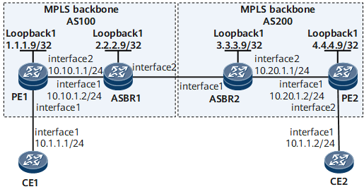
Networking Requirements
On the network shown in Figure 1, CE1 and CE2 access the MPLS backbone network through PE1 in AS100 and PE2 in AS200, respectively.
Inter-AS LDP VPWS Option A needs to be deployed for CE1 and CE2 to communicate.

Configuration Roadmap
The configuration roadmap is as follows:
Configure an IGP for each AS on the MPLS backbone network to ensure IP connectivity within the same AS.
Configure basic MPLS functions on the MPLS backbone network and establish a dynamic LSP between the PE and ASBR in the same AS. If the PE and ASBR are not directly connected, establish a remote LDP session between them.
Configure PEs to exchange VPWS information as BGP peers.
Establish a BGP VPWS connection between the PE and ASBR in the same AS.
Data Preparation
To complete the configuration, you need the following data:
IP address of the remote peer
Data for configuring the IGP
MPLS LSR IDs (local loopback interface IP addresses) of PEs and ASBRs
Procedure
- Configure interface IP addresses.
# Configure CE1.
<HUAWEI> system-view
[~HUAWEI] sysname CE1
[*HUAWEI] commit
[~CE1] interface gigabitethernet 0/1/0
[*CE1-GigabitEthernet0/1/0] ip address 10.1.1.1 24
[*CE1-GigabitEthernet0/1/0] quit
[*CE1] commit
# Configure PE1.
<HUAWEI> system-view
[~HUAWEI] sysname PE1
[*HUAWEI] commit
[~PE1] interface loopback1
[*PE1-Loopback1] ip address 1.1.1.9 32
[*PE1-Loopback1] quit
[*PE1] interface gigabitethernet 0/1/8
[*PE1-GigabitEthernet0/1/8] ip address 10.10.1.1 24
[*PE1-GigabitEthernet0/1/8] quit
[*PE1] commit
# Configure ASBR1.
<HUAWEI> system-view
[~HUAWEI] sysname ASBR1
[*HUAWEI] commit
[~ASBR1] interface loopback1
[*ASBR1-Loopback1] ip address 2.2.2.9 32
[*ASBR1-Loopback1] quit
[*ASBR1] interface gigabitethernet 0/1/0
[*ASBR1-GigabitEthernet0/1/0] ip address 10.10.1.2 24
[*ASBR1-GigabitEthernet0/1/0] quit
[*ASBR1] commit
# Configure ASBR2.
<HUAWEI> system-view
[~HUAWEI] sysname ASBR2
[*HUAWEI] commit
[~ASBR2] interface loopback1
[*ASBR2-Loopback1] ip address 3.3.3.9 32
[*ASBR2-Loopback1] quit
[*ASBR2] interface gigabitethernet 0/1/8
[*ASBR2-GigabitEthernet0/1/8] ip address 10.20.1.1 24
[*ASBR2-GigabitEthernet0/1/8] quit
[*ASBR2] commit
# Configure PE2.
<HUAWEI> system-view
[~HUAWEI] sysname PE2
[*HUAWEI] commit
[~PE2] interface loopback1
[*PE2-Loopback1] ip address 4.4.4.9 32
[*PE2-Loopback1] quit
[*PE2] interface gigabitethernet 0/1/0
[*PE2-GigabitEthernet0/1/0] ip address 10.20.1.2 24
[*PE2-GigabitEthernet0/1/0] quit
[*PE2] commit
# Configure CE2.
<HUAWEI> system-view
[~HUAWEI] sysname CE2
[*HUAWEI] commit
[~CE2] interface gigabitethernet 0/1/0
[*CE2-GigabitEthernet0/1/0] ip address 10.1.1.2 24
[*CE2-GigabitEthernet0/1/0] quit
[*CE2] commit
- Configure an IGP on the MPLS backbone network.
# Configure PE1.
[~PE1] ospf 1
[*PE1-ospf-1] area 0.0.0.0
[*PE1-ospf-1-area-0.0.0.0] network 1.1.1.9 0.0.0.0
[*PE1-ospf-1-area-0.0.0.0] network 10.10.1.0 0.0.0.255
[*PE1-ospf-1-area-0.0.0.0] quit
[*PE1-ospf-1] quit
[*PE1] commit
# Configure ASBR1.
[~ASBR1] ospf 1
[*ASBR1-ospf-1] area 0.0.0.0
[*ASBR1-ospf-1-area-0.0.0.0] network 2.2.2.9 0.0.0.0
[*ASBR1-ospf-1-area-0.0.0.0] network 10.10.1.0 0.0.0.255
[*ASBR1-ospf-1-area-0.0.0.0] quit
[*ASBR1-ospf-1] quit
[*ASBR1] commit
# Configure ASBR2.
[~ASBR2] ospf 1
[*ASBR2-ospf-1] area 0.0.0.0
[*ASBR2-ospf-1-area-0.0.0.0] network 3.3.3.9 0.0.0.0
[*ASBR2-ospf-1-area-0.0.0.0] network 10.20.1.0 0.0.0.255
[*ASBR2-ospf-1-area-0.0.0.0] quit
[*ASBR2-ospf-1] quit
[*ASBR2] commit
# Configure PE2.
[~PE2] ospf 1
[*PE2-ospf-1] area 0.0.0.0
[*PE2-ospf-1-area-0.0.0.0] network 4.4.4.9 0.0.0.0
[*PE2-ospf-1-area-0.0.0.0] network 10.20.1.0 0.0.0.255
[*PE2-ospf-1-area-0.0.0.0] quit
[*PE2-ospf-1] quit
[*PE2] commit
- Configure basic MPLS functions and establish LSPs.
# Configure PE1.
[~PE1] mpls lsr-id 1.1.1.9
[*PE1] mpls
[*PE1-mpls] quit
[*PE1] mpls ldp
[*PE1-mpls-ldp] quit
[*PE1] interface gigabitethernet 0/1/8
[*PE1-GigabitEthernet0/1/8] mpls
[*PE1-GigabitEthernet0/1/8] mpls ldp
[*PE1-GigabitEthernet0/1/8] quit
[*PE1] commit
# Configure ASBR1.
[~ASBR1] mpls lsr-id 2.2.2.9
[*ASBR1] mpls
[*ASBR1-mpls] quit
[*ASBR1] mpls ldp
[*ASBR1-mpls-ldp] quit
[*ASBR1] interface gigabitethernet 0/1/0
[*ASBR1-GigabitEthernet0/1/0] mpls
[*ASBR1-GigabitEthernet0/1/0] mpls ldp
[*ASBR1-GigabitEthernet0/1/0] quit
[*ASBR1] commit
# Configure ASBR2.
[~ASBR2] mpls lsr-id 3.3.3.9
[*ASBR2] mpls
[*ASBR2-mpls] quit
[*ASBR2] mpls ldp
[*ASBR2-mpls-ldp] quit
[*ASBR2] interface gigabitethernet 0/1/8
[*ASBR2-GigabitEthernet0/1/8] mpls
[*ASBR2-GigabitEthernet0/1/8] mpls ldp
[*ASBR2-GigabitEthernet0/1/8] quit
[*ASBR2] commit
# Configure PE2.
[~PE2] mpls lsr-id 4.4.4.9
[*PE2] mpls
[*PE2-mpls] quit
[*PE2] mpls ldp
[*PE2-mpls-ldp] quit
[*PE2] interface gigabitethernet 0/1/0
[*PE2-GigabitEthernet0/1/0] mpls
[*PE2-GigabitEthernet0/1/0] mpls ldp
[*PE2-GigabitEthernet0/1/0] quit
[*PE2] commit
- Configure PEs to exchange VPWS information as BGP peers.
# Configure PE1.
[~PE1] bgp 100
[*PE1-bgp] peer 2.2.2.9 as-number 100
[*PE1-bgp] peer 2.2.2.9 connect-interface loopback 1
[*PE1-bgp] l2vpn-ad-family
[*PE1-bgp-af-l2vpn-ad] peer 2.2.2.9 enable
[*PE1-bgp-af-l2vpn-ad] peer 2.2.2.9 signaling vpws
[*PE1-bgp-af-l2vpn-ad] quit
[*PE1-bgp] quit
[*PE1] commit
# Configure ASBR1.
[~ASBR1] bgp 100
[*ASBR1-bgp] peer 1.1.1.9 as-number 100
[*ASBR1-bgp] peer 1.1.1.9 connect-interface loopback 1
[*ASBR1-bgp] l2vpn-ad-family
[*ASBR1-bgp-af-l2vpn-ad] peer 1.1.1.9 enable
[*ASBR1-bgp-af-l2vpn-ad] peer 1.1.1.9 signaling vpws
[*ASBR1-bgp-af-l2vpn-ad] quit
[*ASBR1-bgp] quit
[*ASBR1] commit
# Configure ASBR2.
[~ASBR2] bgp 200
[*ASBR2-bgp] peer 4.4.4.9 as-number 200
[*ASBR2-bgp] peer 4.4.4.9 connect-interface loopback 1
[*ASBR2-bgp] l2vpn-ad-family
[*ASBR2-bgp-af-l2vpn-ad] peer 4.4.4.9 enable
[*ASBR2-bgp-af-l2vpn-ad] peer 4.4.4.9 signaling vpws
[*ASBR2-bgp-af-l2vpn-ad] quit
[*ASBR2-bgp] quit
[*ASBR2] commit
# Configure PE2.
[~PE2] bgp 200
[*PE2-bgp] peer 3.3.3.9 as-number 200
[*PE2-bgp] peer 3.3.3.9 connect-interface loopback 1
[*PE2-bgp] l2vpn-ad-family
[*PE2-bgp-af-l2vpn-ad] peer 3.3.3.9 enable
[*PE2-bgp-af-l2vpn-ad] peer 3.3.3.9 signaling vpws
[*PE2-bgp-af-l2vpn-ad] quit
[*PE2-bgp] quit
[*PE2] commit
- Configure a BGP connection.
# Configure PE1.
[~PE1] mpls l2vpn
[*PE1-l2vpn] quit
[*PE1] mpls l2vpn vpn1 encapsulation ethernet
[*PE1-mpls-l2vpn-vpn1] route-distinguisher 100:1
[*PE1-mpls-l2vpn-vpn1] vpn-target 1:1 both
[*PE1-mpls-l2vpn-vpn1] ce ce1 id 1 range 10
[*PE1-mpls-l2vpn-vpn1-ce-ce1] connection ce-offset 2 interface gigabitethernet 0/1/0
[*PE1-mpls-l2vpn-vpn1-ce-ce1] quit
[*PE1-mpls-l2vpn-vpn1] quit
[*PE1] commit
# Configure ASBR1.
[~ASBR1] mpls l2vpn
[*ASBR1-l2vpn] quit
[*ASBR1] mpls l2vpn vpn1 encapsulation ethernet
[*ASBR1-mpls-l2vpn-vpn1] route-distinguisher 100:1
[*ASBR1-mpls-l2vpn-vpn1] vpn-target 1:1 both
[*ASBR1-mpls-l2vpn-vpn1] ce ce2 id 2 range 10
[*ASBR1-mpls-l2vpn-vpn1-ce-ce2] connection ce-offset 1 interface gigabitethernet 0/1/8
[*ASBR1-mpls-l2vpn-vpn1-ce-ce2] quit
[*ASBR1-mpls-l2vpn-vpn1] quit
[*ASBR1] commit
# Configure ASBR2.
[~ASBR2] mpls l2vpn
[*ASBR2-l2vpn] quit
[*ASBR2] mpls l2vpn vpn1 encapsulation ethernet
[*ASBR2-mpls-l2vpn-vpn1] route-distinguisher 200:1
[*ASBR2-mpls-l2vpn-vpn1] vpn-target 1:1 both
[*ASBR2-mpls-l2vpn-vpn1] ce ce3 id 3 range 10
[*ASBR2-mpls-l2vpn-vpn1-ce-ce3] connection ce-offset 4 interface gigabitethernet 0/1/0
[*ASBR2-mpls-l2vpn-vpn1-ce-ce3] quit
[*ASBR2-mpls-l2vpn-vpn1] quit
[*ASBR2] commit
# Configure PE2.
[~PE2] mpls l2vpn
[*PE2-l2vpn] quit
[*PE2] mpls l2vpn vpn1 encapsulation ethernet
[*PE2-mpls-l2vpn-vpn1] route-distinguisher 200:1
[*PE2-mpls-l2vpn-vpn1] vpn-target 1:1 both
[*PE2-mpls-l2vpn-vpn1] ce ce4 id 4 range 10
[*PE2-mpls-l2vpn-vpn1-ce-ce4] connection ce-offset 3 interface gigabitethernet 0/1/8
[*PE2-mpls-l2vpn-vpn1-ce-ce4] quit
[*PE2-mpls-l2vpn-vpn1] quit
[*PE2] commit
- Verify the configuration.
After completing the configuration, run the display mpls l2vpn connection interface gigabitethernet command on each PE. The command output shows that a BGP VC has been established and is in the Up state. The following example uses the command output on PE1.
[~PE1] display mpls l2vpn connection interface gigabitethernet 0/1/0
conn-type: remote
     local vc state:             up
     remote vc state:            up
     local ce-id:                1
     local ce name:              ce1
     remote ce-id:               2
     intf(state,encap):          GigabitEthernet0/1/0(up,ethernet)
     peer id:                    2.2.2.9
     route-distinguisher:        100:1
     local vc label:             294930
     remote vc label:            294929
     tunnel policy:              default
     CKey:                       65
     NKey:                       3841982617
     primary or secondary:       primary
     forward entry exist or not: true
     forward entry active or not:true
     manual fault set or not:    not set
     AC OAM state:               up
     BFD for PW session index:   --
     BFD for PW state:           invalid
     BFD for LSP state:          true
     Local C bit is not set
     Remote C bit is not set
     tunnel type:                ldp
     tunnel id:                  0x0000000001004c6b42
CE1 and CE2 can ping each other. The following example uses the command output on CE1.
[~CE1] ping 10.1.1.2
  PING 10.1.1.2: 56  data bytes, press CTRL_C to break
    Reply from 10.1.1.2: bytes=56 Sequence=1 ttl=255 time=430 ms
    Reply from 10.1.1.2: bytes=56 Sequence=2 ttl=255 time=220 ms
    Reply from 10.1.1.2: bytes=56 Sequence=3 ttl=255 time=190 ms
    Reply from 10.1.1.2: bytes=56 Sequence=4 ttl=255 time=190 ms
    Reply from 10.1.1.2: bytes=56 Sequence=5 ttl=255 time=190 ms

  --- 10.1.1.2 ping statistics ---
    5 packet(s) transmitted
    5 packet(s) received
    0.00% packet loss
    round-trip min/avg/max = 190/244/430 ms
Configuration Files
CE1 configuration file
#
sysname CE1
#
interface GigabitEthernet0/1/0
 undo shutdown
 ip address 10.1.1.1 255.255.255.0
#
return
CE2 configuration file
#
sysname CE2
#
interface GigabitEthernet0/1/0
 undo shutdown
 ip address 10.1.1.2 255.255.255.0
#
return
PE1 configuration file
#
sysname PE1
#
mpls lsr-id 1.1.1.9
#
mpls
#
mpls l2vpn
#
mpls ldp
#
interface GigabitEthernet0/1/8
 undo shutdown
 ip address 10.10.1.1 255.255.255.0
 mpls
 mpls ldp
#
interface LoopBack1
 ip address 1.1.1.9 255.255.255.255
#
mpls l2vpn vpn1 encapsulation ethernet
 route-distinguisher 100:1
 vpn-target 1:1 import-extcommunity
 vpn-target 1:1 export-extcommunity
 ce ce1 id 1 range 10 default-offset 0
  connection ce-offset 2 interface GigabitEthernet0/1/0
#
bgp 100
 peer 2.2.2.9 as-number 100
 peer 2.2.2.9 connect-interface LoopBack1
 #
 ipv4-family unicast
  undo synchronization
  peer 2.2.2.9 enable
 #
 l2vpn-ad-family
  policy vpn-target
  peer 2.2.2.9 enable
  peer 2.2.2.9 signaling vpws
#
ospf 1
 area 0.0.0.0
  network 1.1.1.9 0.0.0.0
  network 10.10.1.0 0.0.0.255
#
return
ASBR1 configuration file
#
sysname ASBR1
#
mpls lsr-id 2.2.2.9
#
mpls
#
mpls l2vpn
#
mpls ldp
#
interface GigabitEthernet0/1/0
 undo shutdown
 ip address 10.10.1.2 255.255.255.0
 mpls
 mpls ldp
#
interface GigabitEthernet0/1/8
 undo shutdown
#
interface LoopBack1
 ip address 2.2.2.9 255.255.255.255
#
mpls l2vpn vpn1 encapsulation ethernet
 route-distinguisher 100:1
 vpn-target 1:1 import-extcommunity
 vpn-target 1:1 export-extcommunity
 ce ce2 id 2 range 10 default-offset 0
  connection ce-offset 1 interface GigabitEthernet0/1/8
#
bgp 100
 peer 1.1.1.9 as-number 100
 peer 1.1.1.9 connect-interface LoopBack1
 #
 ipv4-family unicast
  undo synchronization
  peer 1.1.1.9 enable
 #
 l2vpn-ad-family
  policy vpn-target
  peer 1.1.1.9 enable
  peer 1.1.1.9 signaling vpws
#
ospf 1
 area 0.0.0.0
  network 2.2.2.9 0.0.0.0
  network 10.10.1.0 0.0.0.255
#
return
ASBR2 configuration file
#
sysname ASBR2
#
mpls lsr-id 3.3.3.9
#
mpls
#
mpls l2vpn
#
mpls ldp
#
interface GigabitEthernet0/1/0
 undo shutdown
#
interface GigabitEthernet0/1/8
 undo shutdown
 ip address 10.20.1.1 255.255.255.0
 mpls
 mpls ldp
#
interface LoopBack1
 ip address 3.3.3.9 255.255.255.0
#
mpls l2vpn vpn1 encapsulation ethernet
 route-distinguisher 200:1
 vpn-target 1:1 import-extcommunity
 vpn-target 1:1 export-extcommunity
 ce ce3 id 3 range 10 default-offset 0
  connection ce-offset 4 interface GigabitEthernet0/1/0
#
bgp 200
 peer 4.4.4.9 as-number 200
 peer 4.4.4.9 connect-interface LoopBack1
 #
 ipv4-family unicast
  undo synchronization
  peer 4.4.4.9 enable
 #
 l2vpn-ad-family
  policy vpn-target
  peer 4.4.4.9 enable
  peer 4.4.4.9 signaling vpws
#
ospf 1
 area 0.0.0.0
  network 3.3.3.9 0.0.0.0
  network 10.20.1.0 0.0.0.255
#
return
PE2 configuration file
#
sysname PE2
#
mpls lsr-id 4.4.4.9
#
mpls
#
mpls l2vpn
#
mpls ldp
#
interface GigabitEthernet0/1/0
 undo shutdown
 ip address 10.20.1.2 255.255.255.0
 mpls
 mpls ldp
#
interface GigabitEthernet0/1/8
 undo shutdown
#
interface LoopBack1
 ip address 4.4.4.9 255.255.255.0
#
mpls l2vpn vpn1 encapsulation ethernet
 route-distinguisher 200:1
 vpn-target 1:1 import-extcommunity
 vpn-target 1:1 export-extcommunity
 ce ce4 id 4 range 10 default-offset 0
  connection ce-offset 3 interface GigabitEthernet0/1/8
#
bgp 200
 peer 3.3.3.9 as-number 200
 peer 3.3.3.9 connect-interface LoopBack1
 #
 ipv4-family unicast
  undo synchronization
  peer 3.3.3.9 enable
 #
 l2vpn-ad-family
  policy vpn-target
  peer 3.3.3.9 enable
  peer 3.3.3.9 signaling vpws
#
ospf 1
 area 0.0.0.0
  network 4.4.4.9 0.0.0.0
  network 10.20.1.0 0.0.0.255
#
return