Example for Configuring IPv6 VXLAN in Distributed Gateway Mode Using BGP EVPN
This section provides an example for deploying IPv6 VXLAN in distributed gateway mode using BGP EVPN.
Networking Requirements
In IPv6 VXLAN, distributed gateways can be configured to address problems that occur in centralized gateway networking. Such problems include sub-optimal forwarding paths and bottlenecks on Layer 3 gateways in terms of ARP or ND entry specifications.
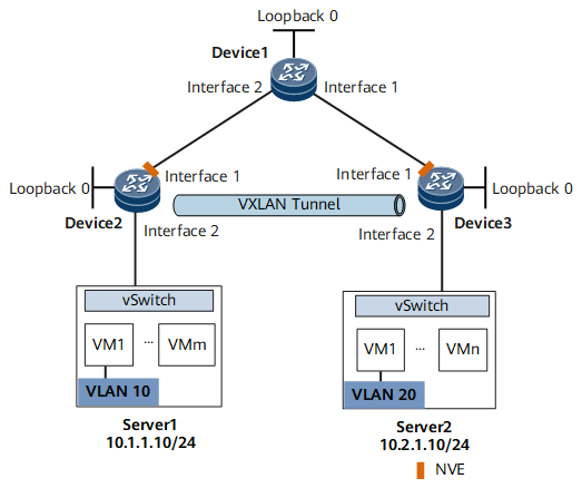
As shown in Figure 1, an enterprise deploys IPv4 VMs in different areas of an IPv6 DC. IPv4 VM1 on Server1 belongs to VLAN 10, and IPv4 VM1 on Server2 belongs to VLAN 20. The two VMs reside on different network segments. IPv6 VXLAN in distributed gateway mode is required for communication between IPv4 VM1s on different servers.

Interface1 and Interface2 in this example represent GigabitEthernet 0/1/0 and GigabitEthernet 0/1/1, respectively.
Device |
Interface |
IP Address and Mask |
|---|---|---|
Device1 |
GigabitEthernet 0/1/0 |
2001:DB8:3::2/64 |
GigabitEthernet 0/1/1 |
2001:DB8:2::2/64 |
|
LoopBack0 |
2001:DB8:11::1/128 |
|
Device2 |
GigabitEthernet 0/1/0 |
2001:DB8:2::1/64 |
LoopBack0 |
2001:DB8:22::2/128 |
|
Device3 |
GigabitEthernet 0/1/0 |
2001:DB8:3::1/64 |
LoopBack0 |
2001:DB8:33::3/128 |
Configuration Roadmap
- Configure OSPFv3 to run between Device1 and Device2 and between Device1 and Device3.
- Configure a service access point on Device2 and Device3 to differentiate service traffic.
- Configure Device2 and Device3 to establish BGP EVPN peer relationships with Device1.
- Configure Device1 to establish BGP EVPN peer relationships with Device2 and Device3. Then, configure Device1 as the RR.
- Configure a VPN instance and an EVPN instance on Device2 and Device3.
- Enable ingress replication on Device2 and Device3.
- Configure an IPv6 VXLAN Layer 3 gateway on Device2 and Device3, and configure an IPv4 address for the gateway interface.
- Configure BGP to advertise IRB routes between Device1 and Device2 and between Device1 and Device3.
Data Preparation
To complete the configuration, you need the following data:
- Router IDs of Device1, Device2, and Device3 used by OSPFv3 (1.1.1.1, 2.2.2.2, and 3.3.3.3)
- VM1 VLAN IDs (10 and 20)
- IPv6 addresses of interconnection interfaces between network devices and IPv4 address of the VBDIF interface that functions as the Layer 3 gateway interface
- BD IDs (10 and 20)
- VNI IDs (10 and 20)
- VNI ID in the VPN instance (100)
Procedure
- Assign an IPv6 address for each interface.
Assign an IPv6 address to each interface on Device1, Device2, and Device3 according to Figure 1. For configuration details, see Configuration Files in this section.
- Configure OSPFv3.
# Configure Device1.
<HUAWEI> system-view
[~HUAWEI] sysname Device1
[*HUAWEI] commit
[~Device1] ospfv3 1
[*Device1-ospfv3-1] router-id 1.1.1.1
[*Device1-ospfv3-1] area 0.0.0.0
[*Device1-ospfv3-1-area-0.0.0.0] quit
[*Device1-ospfv3-1] quit
[*Device1] commit
[~Device1] interface loopback 0
[*Device1-LoopBack0] ospfv3 1 area 0.0.0.0
[*Device1-LoopBack0] quit
[*Device1] interface GigabitEthernet0/1/0
[*Device1-GigabitEthernet0/1/0] ospfv3 1 area 0.0.0.0
[*Device1-GigabitEthernet0/1/0] quit
[*Device1] interface GigabitEthernet0/1/1
[*Device1-GigabitEthernet0/1/1] ospfv3 1 area 0.0.0.0
[*Device1-GigabitEthernet0/1/1] quit
[*Device1] commit
The configuration of Device2 and Device3 is similar to the configuration of Device1. For configuration details, see Configuration Files in this section.
- Configure a service access point on Device2 and Device3.
# Configure Device2.
[~Device2] bridge-domain 10
[*Device2-bd10] quit
[*Device2] interface GigabitEthernet0/1/1.1 mode l2
[*Device2-GigabitEthernet0/1/1.1] encapsulation dot1q vid 10
[*Device2-GigabitEthernet0/1/1.1] rewrite pop single
[*Device2-GigabitEthernet0/1/1.1] bridge-domain 10
[*Device2-GigabitEthernet0/1/1.1] quit
[*Device2] commit
Repeat these steps for Device3. For configuration details, see Configuration Files in this section.
- Configure Device2 and Device3 to establish BGP EVPN peer relationships with Device1.
# Configure a BGP EVPN peer relationship on Device2.
[~Device2] bgp 100
[*Device2-bgp] peer 2001:DB8:11::1 as-number 100
[*Device2-bgp] peer 2001:DB8:11::1 connect-interface LoopBack0
[*Device2-bgp] l2vpn-family evpn
[*Device2-bgp-af-evpn] policy vpn-target
[*Device2-bgp-af-evpn] peer 2001:DB8:11::1 enable
[*Device2-bgp-af-evpn] peer 2001:DB8:11::1 advertise encap-type vxlan
[*Device2-bgp-af-evpn] quit
[*Device2-bgp] quit
[*Device2] commit
Repeat these steps for Device3. For configuration details, see Configuration Files in this section.
- Configure Device1 to establish BGP EVPN peer relationships with Device2 and Device3. Then configure Device1 as the RR and Device2 and Device3 as the RR clients.
# Configure Device1.
[~Device1] bgp 100
[*Device1-bgp] peer 2001:DB8:22::2 as-number 100
[*Device1-bgp] peer 2001:DB8:22::2 connect-interface LoopBack0
[*Device1-bgp] peer 2001:DB8:33::3 as-number 100
[*Device1-bgp] peer 2001:DB8:33::3 connect-interface LoopBack0
[*Device1-bgp] l2vpn-family evpn
[*Device1-bgp-af-evpn] peer 2001:DB8:22::2 enable
[*Device1-bgp-af-evpn] peer 2001:DB8:22::2 advertise encap-type vxlan
[*Device1-bgp-af-evpn] peer 2001:DB8:22::2 reflect-client
[*Device1-bgp-af-evpn] peer 2001:DB8:33::3 enable
[*Device1-bgp-af-evpn] peer 2001:DB8:33::3 advertise encap-type vxlan
[*Device1-bgp-af-evpn] peer 2001:DB8:33::3 reflect-client
[*Device1-bgp-af-evpn] undo policy vpn-target
[*Device1-bgp-af-evpn] quit
[*Device1-bgp] quit
[*Device1] commit
- Configure a VPN instance and an EVPN instance on Device2 and Device3.
# Configure Device2.
[~Device2] ip vpn-instance vpn1
[*Device2-vpn-instance-vpn1] vxlan vni 100
[*Device2-vpn-instance-vpn1] ipv4-family
[*Device2-vpn-instance-vpn1-af-ipv4] route-distinguisher 11:11
[*Device2-vpn-instance-vpn1-af-ipv4] vpn-target 11:1 evpn
[*Device2-vpn-instance-vpn1-af-ipv4] quit
[*Device2-vpn-instance-vpn1] quit
[*Device2] evpn vpn-instance evrf1 bd-mode
[*Device2-evpn-instance-evrf1] route-distinguisher 10:1
[*Device2-evpn-instance-evrf1] vpn-target 11:1
[*Device2-evpn-instance-evrf1] quit
[*Device2] bridge-domain 10
[*Device2-bd10] vxlan vni 10 split-horizon-mode
[*Device2-bd10] evpn binding vpn-instance evrf1
[*Device2-bd10] quit
[*Device2] commit
Repeat these steps for Device3. For configuration details, see Configuration Files in this section.
- Enable ingress replication on Device2 and Device3.
# Enable ingress replication on Device2.
[~Device2] interface nve 1
[*Device2-Nve1] source 2001:DB8:22::2
[*Device2-Nve1] vni 10 head-end peer-list protocol bgp
[*Device2-Nve1] quit
[*Device2] commit
Repeat these steps for Device3. For configuration details, see Configuration Files in this section.
- Configure Device2 and Device3 as Layer 3 VXLAN gateways.
# Configure Device2.
[~Device2] interface Vbdif10
[*Device2-Vbdif10] ip binding vpn-instance vpn1
[*Device2-Vbdif10] ip address 10.1.1.1 255.255.255.0
[*Device2-Vbdif10] vxlan anycast-gateway enable
[*Device2-Vbdif10] arp collect host enable
[*Device2-Vbdif10] quit
[*Device2] commit
Repeat these steps for Device3. For configuration details, see Configuration Files in this section.
- Configure BGP to advertise IRB routes between Device1 and Device2 and between Device1 and Device3.
# Configure Device1.
[~Device1] bgp 100
[~Device1-bgp] l2vpn-family evpn
[~Device1-bgp-af-evpn] peer 2001:DB8:22::2 advertise irb
[*Device1-bgp-af-evpn] peer 2001:DB8:33::3 advertise irb
[*Device1-bgp-af-evpn] quit
[*Device1-bgp] quit
[*Device1] commit
# Configure Device2.
[~Device2] bgp 100
[~Device2-bgp] l2vpn-family evpn
[~Device2-bgp-af-evpn] peer 2001:DB8:11::1 advertise irb
[*Device2-bgp-af-evpn] quit
[*Device2-bgp] quit
[*Device2] commit
Repeat these steps for Device3. For configuration details, see Configuration Files in this section.
- Verify the configuration.
After completing the configurations, run the display vxlan tunnel command on Device2 and Device3 to check VXLAN tunnel information. The following example uses the command output on Device2.
[*Device2] display vxlan tunnel
Number of vxlan tunnel : 1
Tunnel ID   Source           Destination      State  Type     Uptime
--------------------------------------------------------------------
4026531879  2001:DB8:22::2   2001:DB8:33::3   up     dynamic  00:44:18
VM1s on different servers can communicate. VM1 on Server2 can be pinged from the distributed gateway Device2.
[~Device2] ping -vpn-instance vpn1 10.2.1.10
  PING 10.2.1.10: 300  data bytes, press CTRL_C to break
    Reply from 10.2.1.10: bytes=300 Sequence=1 ttl=254 time=30 ms
    Reply from 10.2.1.10: bytes=300 Sequence=2 ttl=254 time=30 ms
    Reply from 10.2.1.10: bytes=300 Sequence=3 ttl=254 time=30 ms
    Reply from 10.2.1.10: bytes=300 Sequence=4 ttl=254 time=30 ms
    Reply from 10.2.1.10: bytes=300 Sequence=5 ttl=254 time=30 ms

  --- 10.2.1.10 ping statistics ---
    5 packet(s) transmitted
    5 packet(s) received
    0.00% packet loss
    round-trip min/avg/max = 30/30/30 ms
Configuration Files
Device1 configuration file
#
sysname Device1
#
ospfv3 1
 router-id 1.1.1.1
 area 0.0.0.0
#
interface GigabitEthernet0/1/0
 undo shutdown
 ipv6 enable
 ipv6 address 2001:DB8:3::2/64
 ospfv3 1 area 0.0.0.0
#
interface GigabitEthernet0/1/1
 undo shutdown
 ipv6 enable
 ipv6 address 2001:DB8:2::2/64
 ospfv3 1 area 0.0.0.0
#
interface LoopBack0
 ipv6 enable
 ipv6 address 2001:DB8:11::1/128
 ospfv3 1 area 0.0.0.0
#
bgp 100
 peer 2001:DB8:22::2 as-number 100
 peer 2001:DB8:22::2 connect-interface LoopBack0
 peer 2001:DB8:33::3 as-number 100
 peer 2001:DB8:33::3 connect-interface LoopBack0
 #
 l2vpn-family evpn
  undo policy vpn-target
  peer 2001:DB8:22::2 enable
  peer 2001:DB8:22::2 advertise encap-type vxlan
  peer 2001:DB8:22::2 advertise irb
  peer 2001:DB8:22::2 reflect-client
  peer 2001:DB8:33::3 enable
  peer 2001:DB8:33::3 advertise encap-type vxlan
  peer 2001:DB8:33::3 advertise irb
  peer 2001:DB8:33::3 reflect-client
#
return
Device2 configuration file
#
sysname Device2
#
evpn vpn-instance evrf1 bd-mode
 route-distinguisher 10:1
 vpn-target 11:1 export-extcommunity
 vpn-target 11:1 import-extcommunity
#
ip vpn-instance vpn1
 ipv4-family
  route-distinguisher 11:11
  apply-label per-instance
  vpn-target 11:1 export-extcommunity evpn
  vpn-target 11:1 import-extcommunity evpn
 vxlan vni 100
#
bridge-domain 10
 vxlan vni 10 split-horizon-mode
 evpn binding vpn-instance evrf1
#
ospfv3 1
 router-id 2.2.2.2
 area 0.0.0.0
#
interface Vbdif10
 ip binding vpn-instance vpn1
 ip address 10.1.1.1 255.255.255.0
 arp collect host enable
 vxlan anycast-gateway enable
#
interface GigabitEthernet0/1/0
 undo shutdown
 ipv6 enable
 ipv6 address 2001:DB8:2::1/64
 ospfv3 1 area 0.0.0.0
#
interface GigabitEthernet0/1/1.1 mode l2
 encapsulation dot1q vid 10
 rewrite pop single
 bridge-domain 10
#
interface LoopBack0
 ipv6 enable
 ipv6 address 2001:DB8:22::2/128
 ospfv3 1 area 0.0.0.0
#
interface Nve1
 source 2001:DB8:22::2
 vni 10 head-end peer-list protocol bgp
#
bgp 100
 peer 2001:DB8:11::1 as-number 100
 peer 2001:DB8:11::1 connect-interface LoopBack0
 #
 l2vpn-family evpn
  policy vpn-target
  peer 2001:DB8:11::1 enable
  peer 2001:DB8:11::1 advertise encap-type vxlan
  peer 2001:DB8:11::1 advertise irb
#
return
Device3 configuration file
#
sysname Device3
#
evpn vpn-instance evrf1 bd-mode
 route-distinguisher 20:1
 vpn-target 11:1 export-extcommunity
 vpn-target 11:1 import-extcommunity
#
ip vpn-instance vpn1
 ipv4-family
  route-distinguisher 22:22
  apply-label per-instance
  vpn-target 11:1 export-extcommunity evpn
  vpn-target 11:1 import-extcommunity evpn
 vxlan vni 100
#
bridge-domain 20
 vxlan vni 20 split-horizon-mode
 evpn binding vpn-instance evrf1
#
ospfv3 1
 router-id 3.3.3.3
 area 0.0.0.0
#
interface Vbdif20
 ip binding vpn-instance vpn1
 ip address 10.2.1.1 255.255.255.0
 arp collect host enable
 vxlan anycast-gateway enable
#
interface GigabitEthernet0/1/0
 undo shutdown
 ipv6 enable
 ipv6 address 2001:DB8:3::1/64
 ospfv3 1 area 0.0.0.0
#
interface GigabitEthernet0/1/1.1 mode l2
 encapsulation dot1q vid 20
 rewrite pop single
 bridge-domain 20
#
interface LoopBack0
 ipv6 enable
 ipv6 address 2001:DB8:33::3/128
 ospfv3 1 area 0.0.0.0
#
interface Nve1
 source 2001:DB8:33::3
 vni 20 head-end peer-list protocol bgp
#
bgp 100
 peer 2001:DB8:11::1 as-number 100
 peer 2001:DB8:11::1 connect-interface LoopBack0
 #
 l2vpn-family evpn
  policy vpn-target
  peer 2001:DB8:11::1 enable
  peer 2001:DB8:11::1 advertise encap-type vxlan
  peer 2001:DB8:11::1 advertise irb
#
return