Example for Configuring VXLAN in Distributed Gateway Mode Using BGP EVPN
This section provides an example for configuring VXLAN in distributed gateway mode using BGP EVPN.
Networking Requirements
Distributed VXLAN gateways can be configured to address problems that occur in legacy centralized VXLAN gateway networking, for example, forwarding paths are not optimal, and the ARP entry specification is a bottleneck.
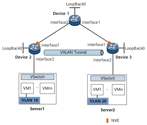
On the network shown in Figure 1, an enterprise has VMs deployed in different data centers. VM 1 on Server 1 belongs to VLAN 10, and VM 1 on Server 2 belongs to VLAN 20. VM 1 on Server 1 and VM 1 on Server 2 reside on different network segments. To allow VM1s in different data centers to communicate with each other, configure distributed VXLAN gateways.

In this example, most configurations are performed on Device 1, Device 2, and Device 3. Devices can be deployed as these devices.
Interfaces 1 and 2 represent GE 0/1/0 and GE 0/1/1, respectively.
Device |
Interface |
IP Address |
|---|---|---|
Device 1 |
GE 0/1/0 |
192.168.3.2/24 |
GE 0/1/1 |
192.168.2.2/24 |
|
Loopback 0 |
1.1.1.1/32 |
|
Device 2 |
GE 0/1/0 |
192.168.2.1/24 |
Loopback 0 |
2.2.2.2/32 |
|
Device 3 |
GE 0/1/0 |
192.168.3.1/24 |
Loopback 0 |
3.3.3.3/32 |
Configuration Roadmap
- Configure IGP to run between Device 1 and Device 2 and between Device 1 and Device 3.
- Configure a service access point on Device 2 and Device 3 to differentiate service traffic.
- Specify Device 1 as a BGP EVPN peer for Device 2 and Device 3.
- Specify Device 2 and Device 3 as BGP EVPN peers for Device 1 and configure Device 2 and Device 3 as RR clients.
- Configure VPN and EVPN instances on Device 2 and Device 3.
- Configure an ingress replication list on Device 2 and Device 3.
- Configure Device 2 and Device 3 as Layer 3 VXLAN gateways.
- Configure IRB route advertisement on Device 1, Device 2, and Device 3.
Data Preparation
To complete the configuration, you need the following data.
- VMs' VLAN IDs (10 and 20)
- IP addresses of interfaces connecting devices
- BD IDs (10 and 20)
- VNI IDs (10 and 20)
- VNI ID in VPN instance (5010)
Procedure
- Configure IGP routing protocol.
Assign an IP address to each interface on Device 1, Device 2, and Device 3 according to Figure 1.
# Configure Device 1.
<HUAWEI> system-view
[~HUAWEI] sysname Device1
[*HUAWEI] commit
[~Device1] isis 1
[*Device1-isis-1] network-entity 10.0000.0000.0001.00
[*Device1-isis-1] quit
[*Device1] commit
[~Device1] interface loopback 0
[*Device1-LoopBack0] ip address 1.1.1.1 32
[*Device1-LoopBack0] isis enable 1
[*Device1-LoopBack0] quit
[*Device1] interface GigabitEthernet0/1/0
[*Device1-GigabitEthernet0/1/0] ip address 192.168.3.2 24
[*Device1-GigabitEthernet0/1/0] isis enable 1
[*Device1-GigabitEthernet0/1/0] quit
[*Device1] interface GigabitEthernet0/1/1
[*Device1-GigabitEthernet0/1/1] ip address 192.168.2.2 24
[*Device1-GigabitEthernet0/1/1] isis enable 1
[*Device1-GigabitEthernet0/1/1] quit
[*Device1] commit
The configuration of Device 2 and Device 3 is similar to the configuration of Device 1. For configuration details, see Configuration Files in this section.
- Configure a service access point on Device 2 and Device 3.
# Configure Device 2.
[~Device2] bridge-domain 10
[*Device2-bd10] quit
[*Device2] interface GigabitEthernet0/1/1.1 mode l2
[*Device2-GigabitEthernet0/1/1.1] encapsulation dot1q vid 10
[*Device2-GigabitEthernet0/1/1.1] rewrite pop single
[*Device2-GigabitEthernet0/1/1.1] bridge-domain 10
[*Device2-GigabitEthernet0/1/1.1] quit
[*Device2] commit
The configuration of Device 3 is similar to the configuration of Device 2. For configuration details, see Configuration Files in this section.
- Specify Device 1 as a BGP EVPN peer for Device 2 and Device 3.# Specify Device 1 as a BGP EVPN peer for Device 2.
[~Device2] bgp 100
[*Device2-bgp] peer 1.1.1.1 as-number 100
[*Device2-bgp] peer 1.1.1.1 connect-interface LoopBack0
[*Device2-bgp] l2vpn-family evpn
[*Device2-bgp-af-evpn] policy vpn-target
[*Device2-bgp-af-evpn] peer 1.1.1.1 enable
[*Device2-bgp-af-evpn] peer 1.1.1.1 advertise encap-type vxlan
[*Device2-bgp-af-evpn] quit
[*Device2-bgp] quit
[*Device2] commit
The configuration of Device 3 is similar to the configuration of Device 2. For configuration details, see Configuration Files in this section.
- Specify Device 2 and Device 3 as BGP EVPN peers for Device 1 and configure them as RR clients.# Specify BGP EVPN peers for Device 1.
[~Device1] bgp 100
[*Device1-bgp] peer 2.2.2.2 as-number 100
[*Device1-bgp] peer 2.2.2.2 connect-interface LoopBack0
[*Device1-bgp] peer 3.3.3.3 as-number 100
[*Device1-bgp] peer 3.3.3.3 connect-interface LoopBack0
[*Device1-bgp] l2vpn-family evpn
[*Device1-bgp-af-evpn] peer 2.2.2.2 enable
[*Device1-bgp-af-evpn] peer 2.2.2.2 advertise encap-type vxlan
[*Device1-bgp-af-evpn] peer 2.2.2.2 reflect-client
[*Device1-bgp-af-evpn] peer 3.3.3.3 enable
[*Device1-bgp-af-evpn] peer 3.3.3.3 advertise encap-type vxlan
[*Device1-bgp-af-evpn] peer 3.3.3.3 reflect-client
[*Device1-bgp-af-evpn] undo policy vpn-target
[*Device1-bgp-af-evpn] quit
[*Device1-bgp] quit
[*Device1] commit
- Configure VPN and EVPN instances on Device 2 and Device 3.
# Configure VPN and EVPN instances on Device 2.
[~Device2] ip vpn-instance vpn1
[*Device2-vpn-instance-vpn1] vxlan vni 5010
[*Device2-vpn-instance-vpn1] ipv4-family
[*Device2-vpn-instance-vpn1-af-ipv4] route-distinguisher 11:11
[*Device2-vpn-instance-vpn1-af-ipv4] vpn-target 11:1 evpn
[*Device2-vpn-instance-vpn1-af-ipv4] quit
[*Device2-vpn-instance-vpn1] quit
[*Device2] evpn vpn-instance evrf3 bd-mode
[*Device2-evpn-instance-evrf3] route-distinguisher 10:1
[*Device2-evpn-instance-evrf3] vpn-target 11:1
[*Device2-evpn-instance-evrf3] quit
[*Device2] bridge-domain 10
[*Device2-bd10] vxlan vni 10 split-horizon-mode
[*Device2-bd10] evpn binding vpn-instance evrf3
[*Device2-bd10] quit
[*Device2] commit
The configuration of Device 3 is similar to the configuration of Device 2. For configuration details, see Configuration Files in this section.
- Configure an ingress replication list on Device 2 and Device 3.# Configure an ingress replication list on Device 2.
[~Device2] interface nve 1
[*Device2-Nve1] source 2.2.2.2
[*Device2-Nve1] vni 10 head-end peer-list protocol bgp
[*Device2-Nve1] quit
[*Device2] commit
The configuration of Device 3 is similar to the configuration of Device 2. For configuration details, see Configuration Files in this section.
- Configure Device 2 and Device 3 as Layer 3 VXLAN gateways.
# Configure Device 2.
[~Device2] interface Vbdif10
[*Device2-Vbdif10] ip binding vpn-instance vpn1
[*Device2-Vbdif10] ip address 10.1.1.1 255.255.255.0
[*Device2-Vbdif10] vxlan anycast-gateway enable
[*Device2-Vbdif10] arp collect host enable
[*Device2-Vbdif10] quit
[*Device2] commit
The configuration of Device 3 is similar to the configuration of Device 2. Note that the IP addresses of VBDIF interfaces on Device 2 and Device 3 must belong to different network segments. For configuration details, see Configuration Files in this section.
- Configure IRB route advertisement on Device 1, Device 2, and Device 3.
# Configure Device 1.
[~Device1] bgp 100
[~Device1-bgp] l2vpn-family evpn
[~Device1-bgp-af-evpn] peer 2.2.2.2 advertise irb
[*Device1-bgp-af-evpn] peer 3.3.3.3 advertise irb
[*Device1-bgp-af-evpn] quit
[*Device1-bgp] quit
[*Device1] commit
# Configure Device 2.
[~Device2] bgp 100
[~Device2-bgp] l2vpn-family evpn
[~Device2-bgp-af-evpn] peer 1.1.1.1 advertise irb
[*Device2-bgp-af-evpn] quit
[*Device2-bgp] quit
[*Device2] commit
The configuration of Device 3 is similar to the configuration of Device 2. For configuration details, see Configuration Files in this section.
- Verify the configuration.
After completing the configurations, run the display vxlan tunnel command on Device 2 and Device 3 to check VXLAN tunnel information. The following example uses the command output on Device 2.
[*Device2] display vxlan tunnel
Number of vxlan tunnel : 1
Tunnel ID   Source           Destination      State  Type     Uptime
--------------------------------------------------------------------
4026531841  2.2.2.2          3.3.3.3          up     dynamic  0026h29m
Run the display bgp evpn all routing-table command to check EVPN route information.
[*Device2]display bgp evpn all routing-table
 Local AS number : 100

 BGP Local router ID is 2.2.2.2
 Status codes: * - valid, > - best, d - damped, x - best external, a - add path,
               h - history,  i - internal, s - suppressed, S - Stale
               Origin : i - IGP, e - EGP, ? - incomplete


 EVN address family:
 Number of Mac Routes: 2
 Route Distinguisher: 10:1
       Network(EthTagId/MacAddrLen/MacAddr/IpAddrLen/IpAddr)  NextHop
 *>    0:48:00e0-fc00-0002:0:0.0.0.0                          0.0.0.0
 Route Distinguisher: 20:1
       Network(EthTagId/MacAddrLen/MacAddr/IpAddrLen/IpAddr)  NextHop
 *>i   0:48:00e0-fc00-0003:0:0.0.0.0                          3.3.3.3

 EVN address family:
 Number of Inclusive Multicast Routes: 2
 Route Distinguisher: 10:1
       Network(EthTagId/IpAddrLen/OriginalIp)                 NextHop
 *>    0:32:2.2.2.2                                           0.0.0.0
 Route Distinguisher: 20:1
       Network(EthTagId/IpAddrLen/OriginalIp)                 NextHop
 *>i   0:32:3.3.3.3                                           3.3.3.3
VM1s on different servers can communicate. You can ping VM1 of Server 2 from the distributed gateway Device 2.
[~Device2] ping -vpn-instance vpn1 10.2.1.10
  PING 10.2.1.10: 300  data bytes, press CTRL_C to break
    Reply from 10.2.1.10: bytes=300 Sequence=1 ttl=254 time=30 ms
    Reply from 10.2.1.10: bytes=300 Sequence=2 ttl=254 time=30 ms
    Reply from 10.2.1.10: bytes=300 Sequence=3 ttl=254 time=30 ms
    Reply from 10.2.1.10: bytes=300 Sequence=4 ttl=254 time=30 ms
    Reply from 10.2.1.10: bytes=300 Sequence=5 ttl=254 time=30 ms

  --- 10.2.1.10 ping statistics ---
    5 packet(s) transmitted
    5 packet(s) received
    0.00% packet loss
    round-trip min/avg/max = 30/30/30 ms
Configuration Files
Device 1 configuration file
#
sysname Device1
#
isis 1
 network-entity 10.0000.0000.0001.00
#
interface GigabitEthernet0/1/0
 undo shutdown
 ip address 192.168.3.2 255.255.255.0
 isis enable 1
#
interface GigabitEthernet0/1/1
 undo shutdown
 ip address 192.168.2.2 255.255.255.0
 isis enable 1
#
interface LoopBack0
 ip address 1.1.1.1 255.255.255.255
 isis enable 1
#
bgp 100
 peer 2.2.2.2 as-number 100
 peer 2.2.2.2 connect-interface LoopBack0
 peer 3.3.3.3 as-number 100
 peer 3.3.3.3 connect-interface LoopBack0
 #
 l2vpn-family evpn
  undo policy vpn-target
  peer 2.2.2.2 enable
  peer 2.2.2.2 advertise encap-type vxlan
  peer 2.2.2.2 advertise irb
  peer 2.2.2.2 reflect-client
  peer 3.3.3.3 enable
  peer 3.3.3.3 advertise encap-type vxlan
  peer 3.3.3.3 advertise irb
  peer 3.3.3.3 reflect-client
#
return
Device 2 configuration file
#
sysname Device2
#
isis 1
 network-entity 10.0000.0000.0002.00
#
ip vpn-instance vpn1
 ipv4-family
  route-distinguisher 11:11
  apply-label per-instance
  vpn-target 11:1 export-extcommunity evpn
  vpn-target 11:1 import-extcommunity evpn
 vxlan vni 5010
#
evpn vpn-instance evrf3 bd-mode
 route-distinguisher 10:1
 vpn-target 11:1 export-extcommunity
 vpn-target 11:1 import-extcommunity
#
bridge-domain 10
 vxlan vni 10 split-horizon-mode
 evpn binding vpn-instance evrf3
#
interface Vbdif10
 ip binding vpn-instance vpn1
 ip address 10.1.1.1 255.255.255.0
 arp collect host enable
 vxlan anycast-gateway enable
#
interface GigabitEthernet0/1/0
 undo shutdown
 ip address 192.168.2.1 255.255.255.0
 isis enable 1
#
interface GigabitEthernet0/1/1.1 mode l2
 encapsulation dot1q vid 10
 rewrite pop single
 bridge-domain 10
#
interface LoopBack0
 ip address 2.2.2.2 255.255.255.255
 isis enable 1
#
interface Nve1
 source 2.2.2.2
 vni 10 head-end peer-list protocol bgp
#
bgp 100
 peer 1.1.1.1 as-number 100
 peer 1.1.1.1 connect-interface LoopBack0
 #
 l2vpn-family evpn
  policy vpn-target
  peer 1.1.1.1 enable
  peer 1.1.1.1 advertise encap-type vxlan
  peer 1.1.1.1 advertise irb
#
return
Device 3 configuration file
#
sysname Device3
#
isis 1
 network-entity 10.0000.0000.0003.00
#
ip vpn-instance vpn1
 ipv4-family
  route-distinguisher 22:22
  apply-label per-instance
  vpn-target 11:1 export-extcommunity evpn
  vpn-target 11:1 import-extcommunity evpn
 vxlan vni 5010
#
evpn vpn-instance evrf3 bd-mode
 route-distinguisher 20:1
 vpn-target 11:1 export-extcommunity
 vpn-target 11:1 import-extcommunity
#
bridge-domain 20
 vxlan vni 20 split-horizon-mode
 evpn binding vpn-instance evrf3
#
interface Vbdif20
 ip binding vpn-instance vpn1
 ip address 10.2.1.1 255.255.255.0
 arp collect host enable
 vxlan anycast-gateway enable
#
interface GigabitEthernet0/1/0
 undo shutdown
 ip address 192.168.3.1 255.255.255.0
 isis enable 1
#
interface GigabitEthernet0/1/1.1 mode l2
 encapsulation dot1q vid 20
 rewrite pop single
 bridge-domain 20
#
interface LoopBack0
 ip address 3.3.3.3 255.255.255.255
 isis enable 1
#
interface Nve1
 source 3.3.3.3
 vni 20 head-end peer-list protocol bgp
#
bgp 100
 peer 1.1.1.1 as-number 100
 peer 1.1.1.1 connect-interface LoopBack0
 #
 l2vpn-family evpn
  policy vpn-target
  peer 1.1.1.1 enable
  peer 1.1.1.1 advertise encap-type vxlan
  peer 1.1.1.1 advertise irb
#
return