Configuring Single-ended SLM in VLL Networking
This section describes how to configure single-ended synthetic loss measurement (SLM) in virtual leased line (VLL) networking. To collect performance statistics for frame loss on point-to-multipoint or multipoint-to-multipoint links, deploy single-ended SLM, which helps monitor link quality.
Context
To collect performance statistics about frame loss on the PW side or AC side at a time or periodically, configure single-ended on-demand synthetic frame LM.
To continuously collect performance statistics about frame loss on the PW side or AC side, configure single-ended proactive synthetic frame LM.
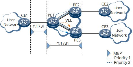
On a network, each packet carries the IEEE 802.1p field, indicating its priority. According to packet priority, different QoS policies will be applied. On the network shown in Figure 1, the PE1-to-PE3 traffic has two priorities: 1 and 2, as indicated by the IEEE 802.1p field.
When implementing single-ended SLM for traffic over the PE1-PE3 link, PE1 sends SLM frames with varied priorities and checks the frame loss. Based on the check result, the network administrator can adjust the QoS policy for the link.
To collect accurate performance statistics, configure 802.1p priority-based single-ended SLM.
Procedure
- Configure single-ended on-demand SLM.
Configure single-ended on-demand SLM on the PW side.
Perform the following steps on the devices at both ends of a PW where single-ended on-demand SLM will be implemented:
Run system-view
The system view is displayed.
Run cfm md md-name
The MD view is displayed.
Run ma ma-name
The MA view is displayed.
- Associate the MA with a service.
-
Run map mpls l2vc[ peer-address ] l2vc-id { raw | tagged }
The MA is bound to a specified L2VC.
-
Run mapmpls l2vpnl2vpn-namecece-idce-offsetce-offset-id
The MA is bound to a specified PW.
-
Configure a MEP according to Table 1.
Table 1 MEP configuration Operation
Command
Configure an interface-based MEP.
mep mep-id mep-id interface { interface-type interface-number | interface-type interface-number.subnumber } [ { pe-vid pe-vid ce-vid ce-vid | vlan vlan-id } ]
Run remote-mep mep-id mep-id
A remote MEP (RMEP) is specified.
-
The MEP is enabled to send continuity check messages (CCMs).
Run remote-mep ccm-receive [ mep-id mep-id ] enable
The RMEP is enabled to receive CCMs.
Run test-id test-id [ testid-file ]mep mep-id [ description description ]
A test instance is created.
Perform the following configuration on the RMEP that receives SLM frames on the PW side:
Run loss-measure single-ended-synthetic receive test-id test-id [ time-out timeout-value ]
The RMEP is enabled to receive SLM frames.
Perform the following configuration on the MEP that sends SLM frames to initiate on-demand SLM on the PW side:
Run loss-measure single-ended-synthetic send test-id test-id interval interval [ sending-count count-value ] [ timeout timeout ]
The MEP is enabled to send SLM frames.
Run commit
The configuration is committed.
Configure single-ended on-demand SLM on the AC side.
Perform the following steps on the devices at both ends of an AC where single-ended on-demand SLM will be implemented:
Run system-view
The system view is displayed.
Run cfm md md-name
The MD view is displayed.
Run ma ma-name
The MA view is displayed.
Perform the following steps on the devices where the MEPs reside:
On the CE, run map vlan vlan-id
The MA is bound to a VLAN.
On the PE, associate the MA with a service.
-
Run map mpls l2vc[ peer-address ] l2vc-id { raw | tagged }
The MA is bound to a specified L2VC.
-
Run mapmpls l2vpnl2vpn-namecece-idce-offsetce-offset-id
The MA is bound to a specified PW.
-
Run mep mep-id
A MEP is configured.
Run remote-mep mep-id mep-id
An RMEP is specified.
-
The MEP is enabled to send CCMs.
Run remote-mep ccm-receive [ mep-id mep-id ] enable
The RMEP is enabled to receive CCMs.
Run test-id test-id mep mep-id remote-mep mep-id [ description description ]
A test instance is created.
Perform the following configuration on the RMEP that receives SLM frames on the AC side:
Run loss-measure single-ended-synthetic receive test-id test-id [ time-out timeout-value ]
The RMEP is enabled to receive SLM frames.
Perform the following configuration on the MEP that sends SLM frames to initiate on-demand SLM on the AC side:
Run loss-measure single-ended-synthetic send test-id test-id interval { 100 | 1000 } [ sending-count count-value ] [ time-out time-out-value ]
The MEP is enabled to send SLM frames.
Run commit
The configuration is committed.
- Configure single-ended proactive SLM.
Perform the following steps on the devices at both ends of a PW or AC where single-ended proactive SLM will be implemented:
Run system-view
The system view is displayed.
(Optional) Run y1731 pm-mode enable
Performance management (PM) is enabled to manage Y.1731 proactive performance statistics.
Run cfm md md-name
The MD view is displayed.
Run ma ma-name
The MA view is displayed.
- Associate the MA with a service.
-
Run map mpls l2vc[ peer-address ] l2vc-id { raw | tagged }
The MA is bound to a specified L2VC.
-
Run mapmpls l2vpnl2vpn-namecece-idce-offsetce-offset-id
The MA is bound to a specified PW.
-
Configure a MEP according to Table 2.
Table 2 MEP configuration Operation
Command
Configure an interface-based MEP.
mep mep-id mep-id interface { interface-type interface-number | interface-type interface-number.subnumber } [ { pe-vid pe-vid ce-vid ce-vid | vlan vlan-id } ]
Configure a PW- or AC-based MEP.
mep mep-id mep-id peer-ip peer-ip [ vc-id vc-id ] [ mac mac-address ] { outward | inward }
(Optional) Run measure-point mep mep-id pw
An interface on the PW side is configured as the measurement point.
This command can be configured only on a PW-based MEP.
Run remote-mep mep-id mep-id
An RMEP is specified.
-
The MEP is enabled to send CCMs.
Run remote-mep ccm-receive [ mep-id mep-id ] enable
The RMEP is enabled to receive CCMs.
Run test-id test-id [ testid-file ]mep mep-id [ description description ]
A test instance is created.
(Optional) Run loss-measure single-ended-synthetic local-ratio-threshold test-id test-id-value upper-limit upper-limit lower-limit lower-limit
Alarm thresholds are configured for the near-end frame loss ratio of proactive SLM.
(Optional) Run loss-measure single-ended-synthetic remote-ratio-threshold test-id test-id-value upper-limit upper-limit lower-limit lower-limit
Alarm thresholds are configured for the far-end frame loss ratio of proactive SLM.
Perform the following configuration on the RMEP that receives SLM frames on the PW side:
Run loss-measure single-ended-synthetic receive test-id test-id [ time-out timeout-value ]
The RMEP is enabled to receive SLM frames.
Perform the following configuration on the MEP that sends SLM frames to initiate proactive SLM on the PW side:
Run loss-measure single-ended-synthetic send test-id test-id interval interval [ sending-count count ] [ time-out timeout ]
The MEP is enabled to send SLM frames.
Run commit
The configuration is committed.
Verifying the Configuration
After configuring single-ended SLM, run the display y1731 statistic-type single-synthetic-loss test-id test-id [ count count ] command on the MEP that has been enabled to send SLM frames.