Basic BFD Concepts
Bidirectional Forwarding Detection (BFD) detects faults in communication between forwarding engines. Specifically, BFD monitors the data protocol connectivity of a path between systems. The path can be a physical or logical link or a tunnel.
BFD interacts with upper-layer applications in the following manner:
An upper-layer application provides BFD with parameters, such as the detection address and interval.
BFD creates, deletes, or modifies sessions based on these parameters and notifies the upper-layer application of the session status.
BFD has the following characteristics:
Provides a low-overhead, short-duration method to detect faults in the path between adjacent forwarding engines.
Provides a single, unified mechanism to monitor any media and protocol layers in real time.
The following sections describe BFD fundamentals, including the BFD detection mechanism, types of links that can be monitored, session establishment modes, and session management.
BFD Detection Mechanism
Two systems establish a BFD session and periodically send BFD Control packets along the path between them. If one system does not receive BFD Control packets within a specified period, the system considers the path faulty.
BFD Control packets are encapsulated in UDP packets for transmission. In the initial phase of a BFD session, both systems negotiate BFD parameters with each other using BFD Control packets. These parameters include discriminators, required minimum intervals at which BFD control packets are sent and received, and local BFD session status. After the negotiation succeeds, BFD Control packets are transmitted along the path at the negotiated interval.
When BFD is applied to different services, both BFD negotiation packets and BFD detection packets are forwarded along the path specified by each service.
BFD detection is performed in either of the following modes:
Asynchronous mode: a major BFD detection mode. In this mode, both systems periodically send BFD Control packets to each other. If one system fails to receive BFD Control packets consecutively, the system considers the BFD session Down.
The echo function can be used when the demand mode is configured. After the echo function is activated, the local system sends a BFD Control packet and the remote system loops back the packet along the forwarding channel. If several consecutive echo packets are not received, the session is declared down.
Types of links that can be monitored by BFD
Link Type |
Sub-Type |
Description |
|---|---|---|
IP link |
|
If a physical Ethernet interface has multiple sub-interfaces, BFD sessions can be separately established on the physical Ethernet interface and its sub-interfaces. |
Eth-Trunk |
|
Separate BFD sessions can be established to monitor an Eth-Trunk interface and its member interfaces at the same time. |
VLANIF |
|
Separate BFD sessions can be established to monitor a VLANIF interface and its member interfaces at the same time. |
MPLS LSP |
|
A BFD session used to monitor the connectivity of MPLS LSPs can be established in either of the following modes:
BFD can monitor a TE tunnel that uses CR-static or RSVP-TE as its signaling protocol and the primary LSP bound to the TE tunnel. |
Segment Routing |
|
BFD for locator route can be applied to SRv6 BE. |
PW |
|
BFD can monitor a PW in static (using a manually configured discriminator) or dynamic mode. |
BFD Session Establishment
BFD sessions can be established in either static or dynamic mode.
BFD identifies sessions based on the My Discriminator (local discriminator) and Your Discriminator (remote discriminator) fields carried in BFD Control packets. The difference between the two modes lies in configurations for the two fields.
Mode |
Description |
|---|---|
Static mode |
BFD session parameters, such as the local and remote discriminators, are manually configured, and a request to create a BFD session is manually delivered.
NOTE:
In static mode, configure unique local and remote discriminators for each BFD session. This mode prevents incorrect discriminators from affecting BFD sessions that are established using correct discriminators and prevents the BFD sessions from alternating between Up and Down. |
Dynamic establishment |
When a BFD session is to be established dynamically, the system processes the local and remote discriminators as follows:
|
BFD Session Management
The BFD session has the following states: Down, Init, Up, and AdminDown.
Down: A BFD session is in the Down state or a request has been sent.
Init: The local end can communicate with the remote end and wants the session state to be Up.
Up: A BFD session is successfully established.
AdminDown: A BFD session is in the AdminDown state.
The BFD status is displayed in the State field of a BFD Control packet. The system changes the session status based on the local session status and the received session status of the peer.
The BFD state machine implements a three-way handshake for BFD session establishment or deletion to ensure that the two systems detect the status changes.
The following shows BFD session establishment to describe the state machine transition process.
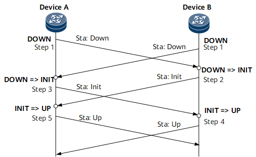
Device A and Device B start their own BFD state machines with the initial state of Down. Device A and Device B send BFD Control packets with the State field set to Down. If a static BFD session is established, the Your Discriminator value in the BFD Control packets is manually specified. If a dynamic BFD session is established, the Your Discriminator value is 0.
After receiving a BFD Control packet with the State field set to Down, Device B switches its state to Init and sends a BFD Control packet with the State field set to Init.

After the local BFD session status changes to Init, Device B no longer processes received BFD Control packets with the State field set to Down.
The BFD status change of Device A is the same as that of Device B, and Device A sends a packet with the State field being Init to Device B.
Upon receipt of the BFD Control packet with the State field set to Init, Device B changes the local status to Up.
The BFD status changes on Device A in the same way as that on Device B.
BFD Protocol Packet
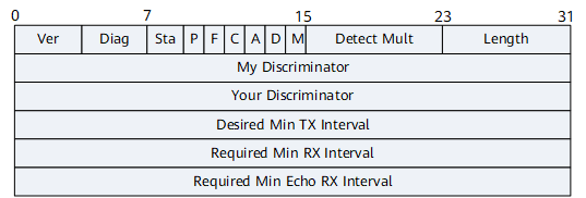
Figure 2 describes the format of a BFD Control packet.
Field |
Length |
Description |
|---|---|---|
Vers (Version) |
3 bits |
BFD protocol version number. It is fixed at 1. |
Diag (Diagnostic) |
5 bits |
Diagnostic word, which indicates the cause of a session status change on the local BFD system:
|
Sta (State) |
2 bits |
Local BFD status:
|
P (Poll) |
1 bit |
Whether the transmit end instructs the receive end to respond to a packet:
|
F (Final) |
1 bit |
Whether the transmit end responds to a packet with the P bit set to 1:
|
C (Control Plane Independent) |
1 bit |
Whether the forwarding plane is separate from the control plane:
|
A (Authentication Present) |
1 bit |
Whether authentication is performed for a BFD session:
|
D (Demand) |
1 bit |
Whether the demand mode is used:
|
M (Multipoint) |
1 bit |
This bit is reserved for BFD to support P2MP extension in the future. |
Detect Mult |
8 bits |
Detection timeout multiplier, which is used by the detecting party to calculate the detection timeout period:
|
Length |
8 bits |
Packet length, in bytes. |
My Discriminator |
32 bits |
Local discriminator of a BFD session. It is a unique non-zero value generated by the transmit end. Local discriminators are used to distinguish multiple BFD sessions of a system. |
Your Discriminator |
32 bits |
Remote discriminator of a BFD session:
|
Desired Min TX Interval |
32 bits |
Locally supported minimum interval (in milliseconds) at which BFD Control packets are sent. |
Required Min RX Interval |
32 bits |
Locally supported minimum interval (in milliseconds) at which BFD Control packets are received. |
Required Min Echo RX Interval |
32 bits |
Locally supported minimum interval (in milliseconds) at which Echo packets are received. Value 0 indicates that the local device does not support the Echo function. |